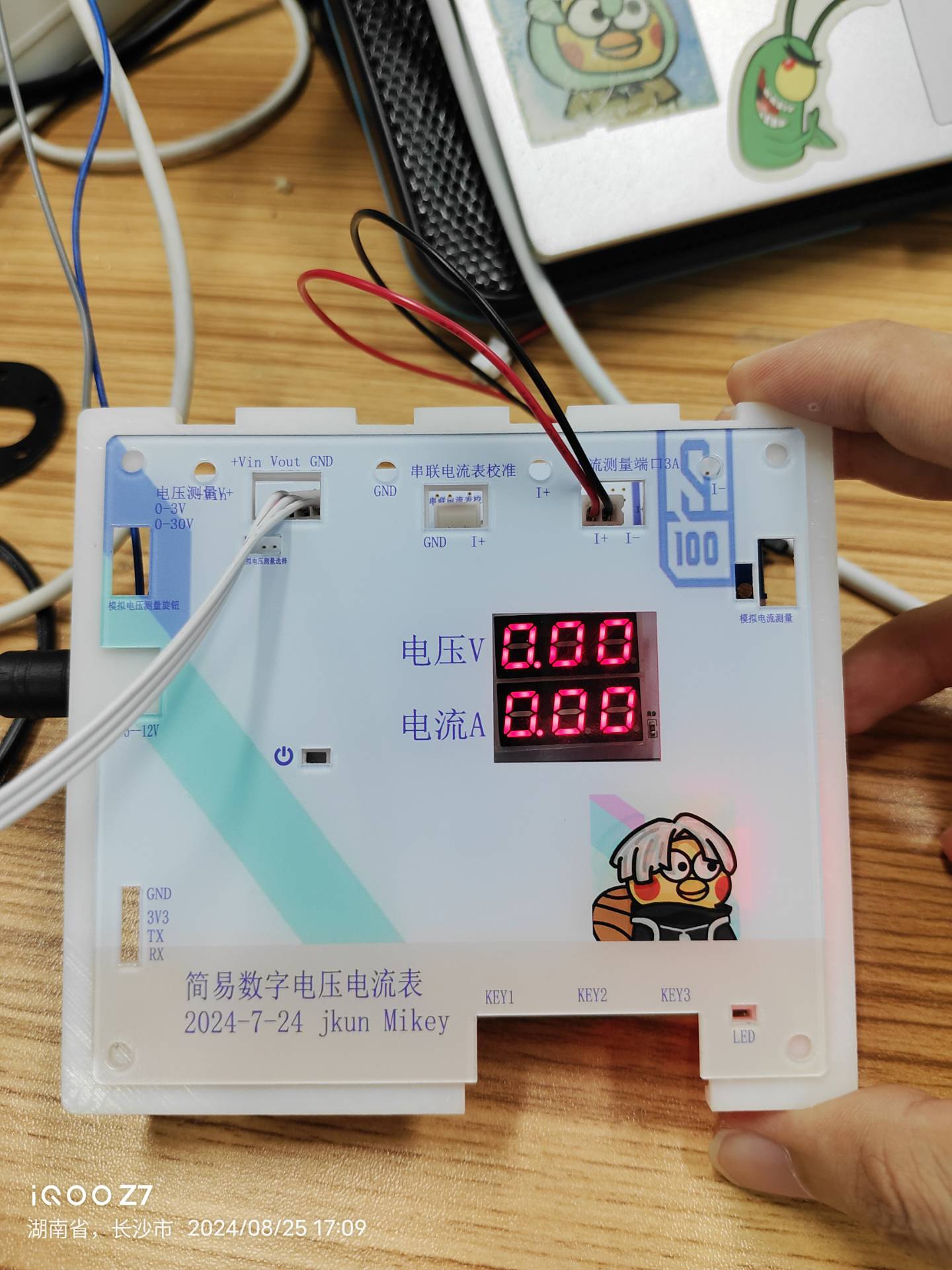
This was my first time making the casing and panel, so it wasn't perfect.
I. Project Introduction
(I) Project Background and Significance
Designing and building a digital voltmeter and ammeter is an excellent way to improve digital and analog electronics technology and microcontroller application capabilities. This project covers multiple aspects such as circuit design, signal acquisition and processing, and user interface development, making it very suitable for electronics beginners.
Through this JLCPCB training camp, I learned a lot by doing it myself—hardware, software, 3D modeling, panel design—and JLCPCB provided free coupons for all of these. It was almost zero cost; as long as you wanted to do it, there were many experts in the group helping to answer questions, creating a fantastic learning atmosphere. This is so much better than what schools teach!
LCPCB development boards truly don't aim to make money by selling boards; their mission is to cultivate Chinese engineers!
In short, I learned a lot through this, discovered my shortcomings, and enjoyed the process.
(II) Project Highlights
After completing the basic functions of the LCSC training camp digital voltmeter and ammeter, I added my own features. The most difficult part was the voltage and current calibration and measurement, both in hardware and software, but after doing it myself, it wasn't so difficult.
1. A small startup animation with two smiley faces:
2. To prevent accidental triggering, I changed KEY1 to a 2-second long press to enter the parameter setting interface. Double-clicking KEY2 confirms the modification of the corresponding calibration parameter value.
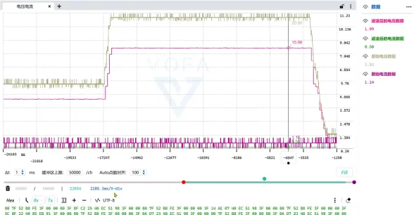
3. Voltage and current data can be sent to a host computer via serial port, or later treated as a module and sent to another microcontroller.
(III) The demonstration video
is finished, and I really learned something! _Bilibili_
https://www.bilibili.com/video/BV1BjWkevE8o/?vd_source=b3782bc780e6d1c9fbdb61b02c6df06b
II. Main Hardware Design
(I)
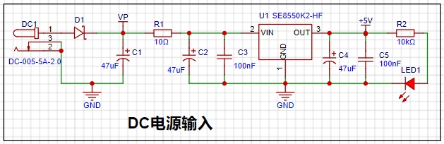
Selection of DC Power Supply LDO (Low Dropout Linear Regulator) This project uses an LDO as the power supply. Considering that most actual voltmeter products are used in industrial scenarios with 24V or 36V power supply, this project selected the SE8550K2 with a maximum input voltage of up to 40V as the power supply. The
SE8550K2 is a low dropout linear regulator with advantages such as stable output, low noise, and simple peripheral circuits. It is widely used in home appliances, communications, industrial control and other fields. Although the efficiency is relatively low, it is suitable for applications that require high-quality power output.
The main reason for not using a DC-DC step-down circuit to deal with the large dropout voltage in this project is to avoid introducing DC-DC ripple interference during the design process. The secondary reason is to reduce project costs.
(II) MCU Selection Analysis
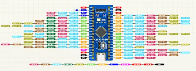
This project uses the LCSC CW32F030C8Tx development board (core board) as the main controller
. 1. Key Advantages of CW32 in this Project
: Wide operating temperature range: -40~105℃
Wide operating voltage range: 1.65V~5.5V (STM32 only supports 3.3V systems)
Strong anti-interference: HBM ESD 8KV All ESD reliability reaches the highest level of international standards (STM32 ESD 2KV)
Project Focus - Better ADC: 12-bit high-speed ADC can reach ±1.0LSB INL 11.3ENOB Multiple Vref reference voltages... ... (STM32 only supports VDD=Vref)
Stable and reliable eFLASH technology.
2. The main characteristics of the CW32's ADC are from the "CW32x030 User Manual"
(Part 3) Voltage Sampling Circuit.
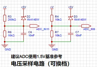
The voltage divider resistors in this project are designed to be 220K+10K, so the voltage division ratio is 22:1 (ADC_IN11).
1. Voltage Divider Resistor Selection
and Design: The maximum value of the measured voltage is 30V for safety reasons (the actual maximum can be displayed as 99.9V or 100V).
The ADC reference voltage is 1.5V in this project, and this reference voltage can be configured through the program.
To reduce the power consumption of the sampling circuit, the low-side resistor (R7) is usually chosen as 10K based on experience.
Then, the high-side resistance of the voltage divider resistor can be calculated using the above parameters.
The required voltage division ratio is calculated, i.e., the ADC reference voltage. The input voltage is designed; using known parameters, 1.5V/30V = 0.05 can be calculated.
The high-side resistance is calculated as the low-side resistance/voltage division ratio; using known parameters, 10K/0.05 = 200K can be calculated.
A standard resistor is selected: a resistor slightly higher than the calculated value of 200K is chosen. We usually choose E24 series resistors; therefore, in this project, 220K, which is greater than 200K and closest to the calculated value, is selected.
If, in actual use, the voltage to be measured is lower than 2/3 of the module's design voltage (66V), the voltage divider resistor can be replaced and the program modified to improve measurement accuracy. The following example illustrates this:
Assuming the measured voltage is no higher than 24V and other parameters remain unchanged,
calculations show 1.5V/24V = 0.0625, 10K/0.0625 = 160K. 160K is a standard E24 resistor and can be directly selected, or a higher value 180K can be chosen with some redundancy.
If, in actual use, the voltage to be measured is higher than the module's 99V design voltage, a different resistor can be selected. To achieve a wider voltage measurement range, consider replacing the voltage divider resistor or modifying the reference voltage. Here's a case study:
Assuming the measured voltage is 160V, we can choose to increase the voltage reference to expand the range.
Given that the voltage division ratio of the selected resistor is 0.0145, we can calculate 160V * 0.0145 = 2.32V using the formula. Therefore, we can choose a 2.5V voltage reference to increase the range (increasing the range will reduce accuracy).
Considering the potential fluctuations in the measured power supply, a 10nF filter capacitor is connected in parallel with the low-side voltage divider resistor to improve measurement stability.
2. Range Switching
In this project, an additional voltage sampling circuit was added. Therefore, we can discuss the significance of range switching for improving measurement accuracy. Multimeters often have multiple range settings for more accurate measurements. By adjusting different ranges, the optimal measurement accuracy of the measured point within the corresponding range can be obtained.
This project requires a combination of hardware and software to achieve this function. When we first use the ADC_IN11 channel mentioned earlier to measure voltages below 30V... If the measured voltage is within 0~3V, the ADC_IN9 channel is used for measurement. At this time, due to the reduced voltage division ratio, the measurement accuracy is greatly improved.
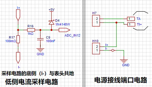
(IV) Current Sampling Circuit
This project uses a low-side current sampling circuit for current detection. The low-side of the sampling circuit shares a common ground with the development board's meter interface.
1. Design Analysis
The sampling current designed for this project is 3A, and the selected sampling resistor (R0) is 100mΩ. The following aspects need to be considered when selecting the sampling resistor: the maximum value of the pre-designed measurement current, the voltage difference caused
by the 3A current sensing resistor in this project , and it is generally not recommended to exceed 0.5V.
The power consumption of the current sensing resistor should be selected based on the appropriate package. Considering the power consumption (temperature) under high current conditions, a 1W metal wire-wound resistor was chosen for this project
. The voltage amplification factor of the current sensing resistor is 1 since no operational amplifier is used in this project.
The current sensing resistance value can then be calculated using the above parameters.
Since no amplifier circuit is used in this project, a larger sampling resistor is needed to obtain a higher measured voltage for measurement.
However, considering that a larger resistor would result in a larger voltage drop and higher power consumption, an unlimited selection of a larger resistor is not possible.
A 1W package resistor was chosen for this project, corresponding to a power rise of 1W
. Based on the above data, a 100mΩ current sensing resistor was selected. According to the formula, 3A * 100mΩ = 300mV, 900mW.
To handle different operating environments, especially high current scenarios, the R0 resistor can be replaced with constantan wire or a shunt. The appropriate alternative can be chosen based on the specific application scenario. For safety and educational purposes, this project will not discuss measurements exceeding 3A, but the principle remains the same.
(V) Digital Tube Display
This project uses digital tubes as the display unit.

Two 0.28-inch three-digit common-cathode digital tubes were used as the display device. Originally, an OLED or LCD was considered, but a mistake was made by forgetting to buy two different colored digital tubes.
The current-limiting resistors (R1~R6) for the digital tubes were configured to 300Ω. This resulted in good visibility for both red and blue digital tubes, with a soft and non-glaring brightness.
Strictly speaking, the current-limiting resistors should be added to the segments; adding them to the digits would affect the display effect. Adding them to the digits saves on resistors.
1. Digital Tube Power Supply
Current This project actually uses dynamic scanning to drive the digital tubes. Therefore, at any given time, only a maximum of 8 segments (or LEDs) of the digital tubes are lit, or in other words, only one digit is lit. According to the design, the required driving current is approximately 11mA (IO port high-level voltage 3.3V ÷ 300Ω).
At this point, it is important to ensure that the selected MCU has sufficient current-pull/sinking capability.
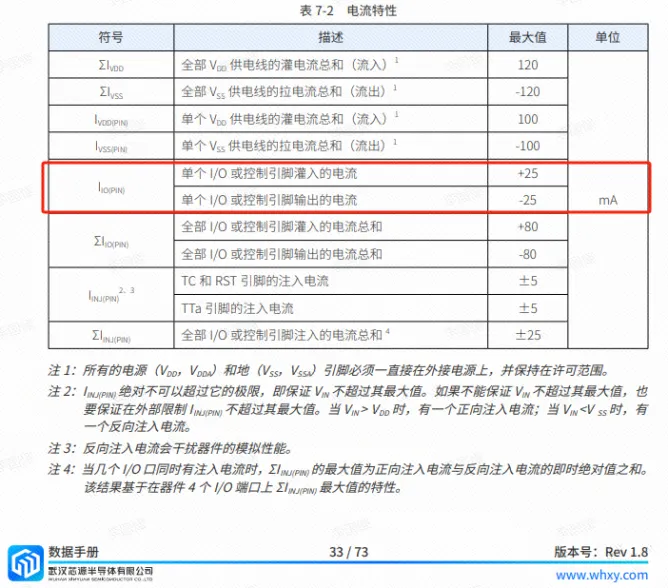
Analysis of the datasheet shows that CW32 meets the requirements.


 京公网安备 11010802033920号

 LT1118-2.5


