Project Description:
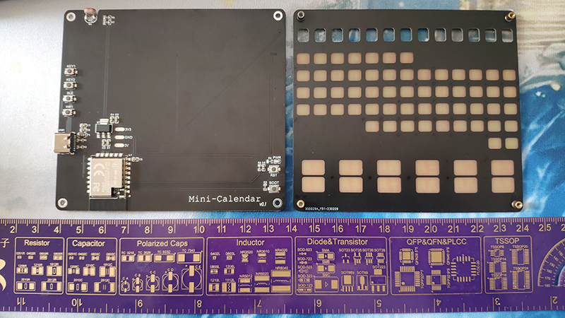
This electronic desk calendar is inspired by a promotional gift for a product endorsed by a celebrity. It uses a single panel and a movable cover to display the entire year's calendar. For ease of production, the size was chosen to be within 10 x 10 cm, hence the name "Mini Electronic Desk Calendar."
All hardware design and software development in this project adhere to the MIT open-source license.
This is the first time this project has been publicly released; it is my original work and has not won any awards in other competitions.
Design Principles:
The main controller chosen is the Anxinke ESP-C3-12F, using WS2812B 2020 LEDs as the light source, a photoresistor for dimming, and a minimalist peripheral circuit using LDOs, RCs, and buttons. Serial port debugging utilizes the built-in USB serial port of the ESP32C3.
IO Pin Function Selection:
IO1: Photoresistor sampling;
IO2-IO5: Function buttons;
IO6, IO7: WS2812B data pins, used to control the day of the week, month, and date lights respectively;
IO9: BOOT pin (automatic downloading is not possible after the first firmware flash via USB serial port, so the BOOT pin and reset button must be retained)
; IO18, IO19: USB serial port
ADC sampling.
The ESP32C3's ADC sampling range is 0V~2.5V. To limit the voltage and improve sampling accuracy, it is recommended that the fixed resistor value be twice the variable resistor value.
According to the datasheet, the GL5537-2 photoresistor has a light resistance of 50K ohms, therefore, resistor R7 should be 100K ohms to ensure that the maximum sampling voltage is 1/3 of the input voltage.
In practice, 2.5dB attenuation was insufficient to measure the specified voltage range, so 0dB attenuation was ultimately chosen.

The
measurable voltage range (mV)
and error (mV) are as follows:
ADC_ATTEN_DB_0
0 ~ 750
±10;
ADC_ATTEN_DB_2_5
0 ~ 1050 ±
10;
ADC_ATTEN_DB_6
0 ~ 1300
±10;
ADC_ATTEN_DB_11
0 ~ 2500
±35 .
For software instructions,
please refer to the documentation in the project "MicroPython Mini Electronic Calendar".
Firmware Burning
: To facilitate firmware burning, an online firmware burning tool is provided. Simply connect the main control board and computer using a data cable to burn the firmware online.
Special Note: When burning firmware to the ESP32-C3-12F module, you need to enter download mode. If a connection timeout occurs during burning, it means the module did not automatically enter download mode. In this case, press and hold the BOOT button and then press the RST button, or unplug and replug the data cable to manually enter download mode. Please see the attached files
for actual
product photos


and videos. My ability
to assemble the parts
is too limited to create a 3D rendering; please use your imagination.
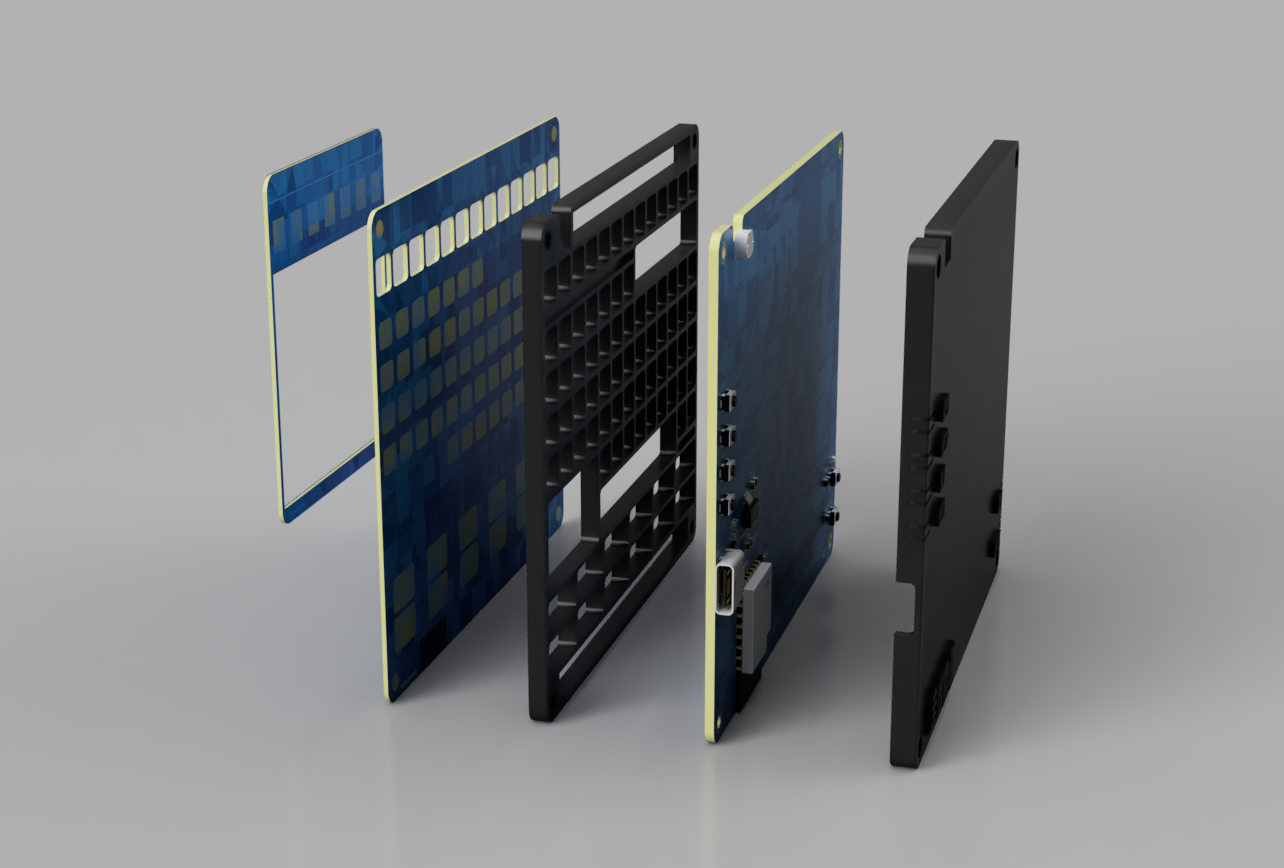
I'm speechless at how well the PCB layout is rendered. The assembly order and materials
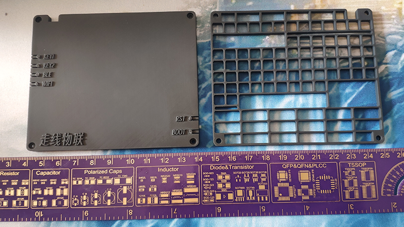
in the rendered image are as follows: Bottom Case * 1 (optional) Optional bottom case requires M2*7 hex screws. Without the bottom case, requires M2*4 hex screws. Main Control Board * 1 Grid Board (choose one of three): Acrylic * 1, approximately 3.5mm thick, black and opaque. 3D Shell * 1, approximately 3.5mm thick, black and opaque, or self-painted. PCB Board * 2, 1.6mm thick; excessive slotting will incur a 50 RMB milling fee. Acrylic and PCB board grid boards have not been verified. Front Panel * 1: M2*3 double-sided knurled copper pillars soldered on the reverse side . 5mm soft magnetic strip pasted on the top of the front. Front Baffle * 1: 5mm soft magnetic strip pasted on the top of the reverse side. Design Notes: Except for 4. Main Control Board, all other items in the design drawing are accessories. Please refer to the BOM shown in 4. Main Control Board for the bill of materials. To learn how to create text-filled areas with arbitrary fonts, please refer to the instructions in this article. Thanks to LEGEND for the selfless help of the reference project ! [RA] Perpetual Calendar Based on Renesas R7FA2E1A72DFL [RA] Perpetual Calendar Based on Renesas R7FA2E1A72DFL Related Videos


 京公网安备 11010802033920号

 TS2CSM1-262.144K200/C


