Hardware Section:
1. 16-Pin Type-C Circuit:

This Type-C circuit can power the entire circuit via VBUS and also perform serial communication for program downloading.
2. Automatic Download Circuit:
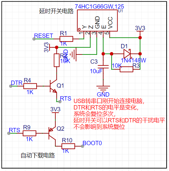
I added a delay switch circuit to the automatic download circuit. When the USB-to-serial adapter is first connected to the computer, the DTR and RTS levels change, causing the system to reset multiple times. The delay switch prevents interference levels in RTS and DTR from affecting the system reset.
3. IP5306 Power Bank Circuit

: The IP5306 requires very few external components, effectively reducing the overall solution size and BOM cost. The IP5306 only needs one inductor to achieve buck and boost functions, supporting low-cost inductors and capacitors. The IP5306's synchronous boost system provides a maximum output current of 2.4A with a conversion efficiency of up to 92%. Under no-load conditions, it automatically enters sleep mode, with the quiescent current dropping to 100uA. Considering the potential sleep issue of the IP5306, I referenced a design from an online blogger and added a GPIO port to continuously wake up the chip, preventing it from going into sleep mode. Reference blog link: Preventing IP5306 from automatically shutting down in low power consumption_IP5306 output stops after 30 seconds - CSDN blog

4.
The peripheral circuit of the original chip manual for the ME2159 DC/DC boost circuit is as follows.
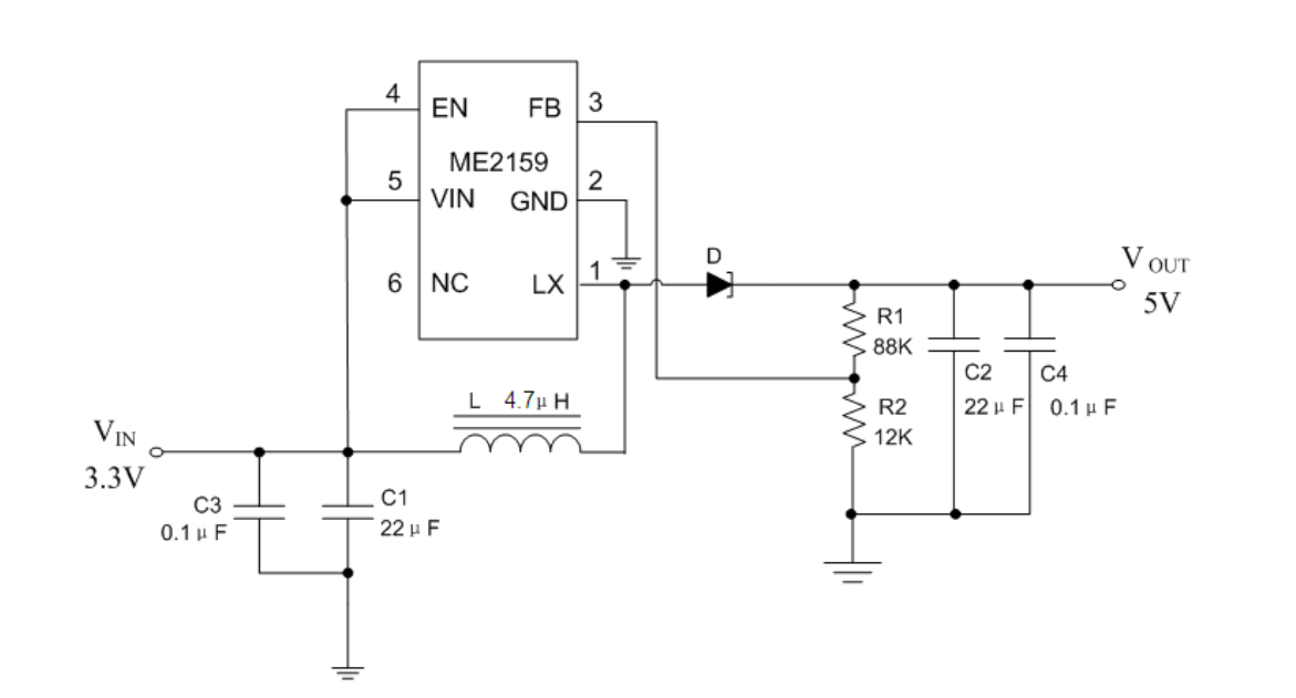
The inductor selection for this circuit must be a power inductor, and the package is preferably 0603. The chip has a precision feedback reference voltage of 0.6V, a reference voltage accuracy of ±2%, an adjustable output of up to 12V, and an internal fixed PWM frequency of 650KHz. It is important to note that the adjustable output voltage is calculated using the resistance values of R1 and R2. The output voltage formula is as follows:

5.


Buck circuit 6. Microcontroller circuit

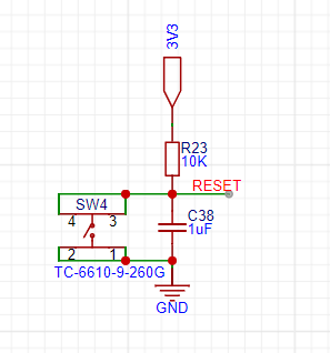
7. Reset circuit
The software part
mainly involves triggering an interrupt via a button. The microcontroller scans the button and transmits parameters to the output comparator register. By detecting the button and triggering an interrupt, the parameters are incremented and decremented, causing the CCR comparator register to change accordingly. The ARR register remains unchanged. By changing the value of the CCR register, the duty cycle of the output PWM is changed, thereby changing the rotation speed of the DC motor.
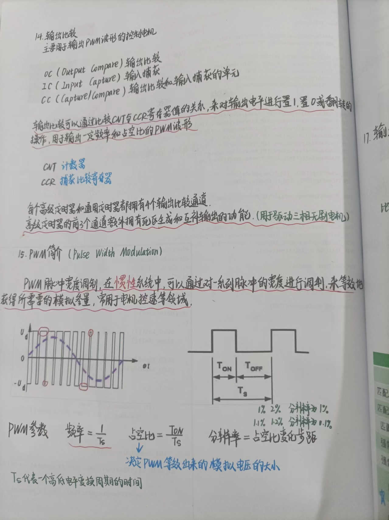

1. PWM output function
#include "stm32f10x.h" // Device header
void PWM_Init(void){ RCC_APB1PeriphClockCmd(RCC_APB1Periph_TIM2, ENABLE); RCC_APB2PeriphClockCmd(RCC_APB2Periph_GPIOA, ENABLE); GPIO_InitTypeDef GPIO_InitStructure; GPIO_InitStructure.GPIO_Mode = GPIO_Mode_AF_PP; GPIO_InitStructure.GPIO_Pin = GPIO_Pin_2|GPIO_Pin_1; GPIO_InitStructure.GPIO_Speed = GPIO_Speed_50MHz; GPIO_Init(GPIOA, &GPIO_InitStructure);
TIM_InternalClockConfig(TIM2); TIM_TimeBaseInitTypeDef TIM_TimeBaseInitStructure; TIM_TimeBaseInitStructure.TIM_ClockDivision = TIM_CKD_DIV1; TIM_TimeBaseInitStructure.TIM_CounterMode = TIM_CounterMode_Up; TIM_TimeBaseInitStructure.TIM_Period = 100 - 1; //ARR TIM_TimeBaseInitStructure.TIM_Prescaler = 36 - 1; //PSC TIM_TimeBaseInitStructure.TIM_RepetitionCounter = 0; TIM_TimeBaseInit(TIM2, &TIM_TimeBaseInitStructure); TIM_OCInitTypeDef TIM_OCInitStructure; TIM_OCStructInit(&TIM_OCInitStructure); TIM_OCInitStructure.TIM_OCMode = TIM_OCMode_PWM1; TIM_OCInitStructure.TIM_OCPolarity = TIM_OCPolarity_High; TIM_OCInitStructure.TIM_OutputState = TIM_OutputState_Enable; TIM_OCInitStructure.TIM_Pulse = 0; //CCR TIM_OC3Init(TIM2, &TIM_OCInitStructure); TIM_OCInitStructure.TIM_OCMode = TIM_OCMode_PWM1; TIM_OCInitStructure.TIM_OCPolarity = TIM_OCPolarity_High; TIM_OCInitStructure.TIM_OutputState = TIM_OutputState_Enable; TIM_OCInitStructure.TIM_Pulse = 0; //CCR TIM_OC2Init(TIM2, &TIM_OCInitStructure); TIM_Cmd(TIM2, ENABLE);}
void PWM_SetCompare3(uint16_t Compare){ TIM_SetCompare3(TIM2, Compare); TIM_SetCompare2(TIM2, Compare);}
2. Motor drive functions
#include "stm32f10x.h" // Device header #include "PWM.h"
void Motor_Init(void){ RCC_APB2PeriphClockCmd(RCC_APB2Periph_GPIOA, ENABLE); GPIO_InitTypeDef GPIO_InitStructure; GPIO_InitStructure.GPIO_Mode = GPIO_Mode_Out_PP; GPIO_InitStructure.GPIO_Pin = GPIO_Pin_3 | GPIO_Pin_4| GPIO_Pin_5| GPIO_Pin_6; GPIO_InitStructure.GPIO_Speed = GPIO_Speed_50MHz; GPIO_Init(GPIO, &GPIO_InitStructure)
; GPIO_Pin_3); GPIO_ResetBits(GPIOA, GPIO_Pin_4); GPIO_SetBits(GPIOA, GPIO_Pin_5); GPIO_ResetBits(GPIOA, GPIO_Pin_6); PWM_SetCompare3(Speed); } else { GPIO_ResetBits(GPIOA, GPIO_Pin_3); GPIO_SetBits(GPIOA, GPIO_Pin_4); GPIO_ResetBits(GPIOA, GPIO_Pin_5); GPIO_SetBits(GPIOA, GPIO_Pin_6); PWM_SetCompare3(-Speed); }}
3. Key press triggers external interrupt function
#include "stm32f10x.h" // Device header #include "Delay.h"
void Key_Init(void){ RCC_APB2PeriphClockCmd(RCC_APB2Periph_GPIOB, ENABLE); GPIO_InitTypeDef GPIO_InitStructure; GPIO_InitStructure.GPIO_Mode = GPIO_Mode_IPU; GPIO_InitStructure.GPIO_Pin = GPIO_Pin_1 | GPIO_Pin_0; GPIO_InitStructure.GPIO_Speed = GPIO_Speed_50MHz; GPIO_Init(GPIOB, &GPIO_InitStructure);}
uint8_t Key_GetNum(void){ uint8_t KeyNum = 0; if (GPIO_ReadInputDataBit(GPIOB, GPIO_Pin_1) == 0) { Delay_ms(20); while (GPIO_ReadInputDataBit(GPIOB, GPIO_Pin_1) == 0); Delay_ms(20); KeyNum = 1; } if (GPIO_ReadInputDataBit(GPIOB, GPIO_Pin_0) == 0) { Delay_ms(20); while (GPIO_ReadInputDataBit(GPIOB, GPIO_Pin_0) == 0); Delay_ms(20); KeyNum = 2; } return KeyNum;}
4. main function
#include "stm32f10x.h" // Device header #include "Delay.h" #include "OLED.h" #include "Motor.h" #include "Key.h" #include "pulse.h"
uint8_t KeyNum;int8_t Speed;
int main(void){ OLED_Init(); Motor_Init(); Key_Init();
OLED_ShowString(2, 1, "Speed:"); uint16_t prescaler = 7200 - 1; // 72MHz / 7200 = 10kHz uint16_t period = 65536 - 1; // 10kHz / 290000 = 29s
TIM3_PWM_Init(period, prescaler);
while (1) { KeyNum = Key_GetNum(); if (KeyNum == 2) { Speed += 20; if (Speed > 100) { Speed = 0; } } Motor_SetSpeed(Speed); OLED_ShowSignedNum(2, 7, Speed, 3); }}
In general, the timer is first initialized to generate a PWM signal, and the frequency and period of the timer are set to meet the control requirements of the motor. Then the output comparator register is configured to generate a PWM signal with the required duty cycle. Different duty cycles correspond to different motor speeds. The duty cycle of the PWM signal is adjusted by setting the output compare register value of the timer as needed. For example, a 50% duty cycle corresponds to medium speed, and a 100% duty cycle corresponds to full speed. When controlling the motor direction, GPIO pins are used to control the direction pins of the H-bridge circuit to achieve forward and reverse rotation of the motor. The motor's rotation direction can be controlled by setting different GPIO pin states. Updating the PWM duty cycle is done by updating the output compare register value of the timer to adjust the duty cycle of the PWM signal; for example, if a command to increase speed is received, the duty cycle is increased.
The video has already been uploaded to Bilibili: https://www.bilibili.com/video/BV1BtgaegERw/?vd_source=1a0773535eda8ace0b6069f8be099662


 京公网安备 11010802033920号

 CY74FCT244ATSOCG4


