These are videos related to speaker construction posted on Bilibili:
https://www.bilibili.com/video/BV1VK421C7FU/?spm_id_from=333.999.0.0
https://www.bilibili.com/video/BV19v421y7Xc/?spm_id_from=333.999.0.0
https://www.bilibili.com/video/BV18P41127zn/?spm_id_from=333.999.0.0
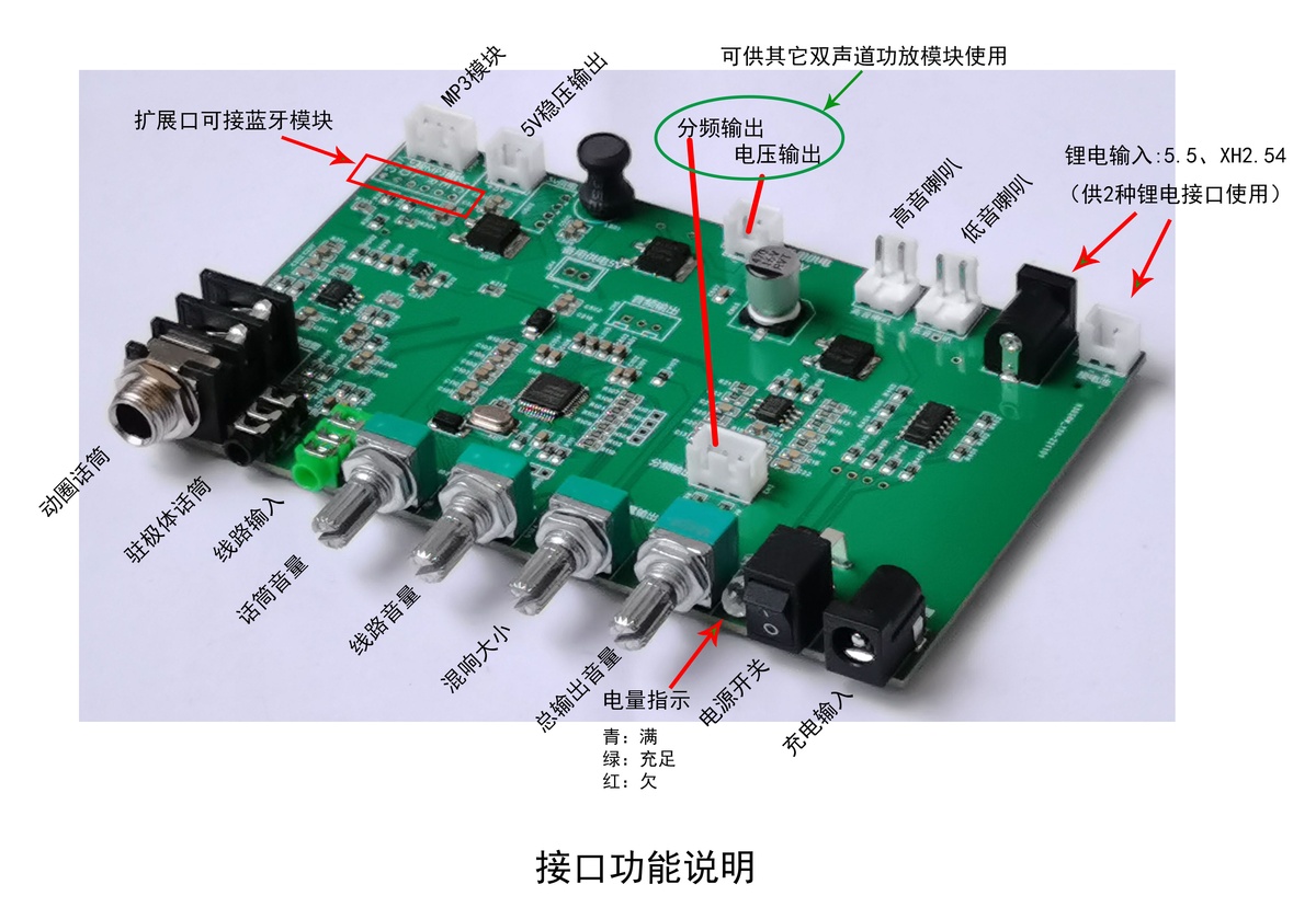
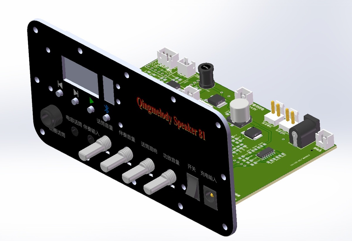
Circuit Introduction
The circuit consists of 7 parts:
1. DSP: Uses a MountainView AP8248 chip salvaged from a V8 sound card, mainly for its reverb and volume control.

2. MIC: Uses a low-voltage, low-noise op-amp (NE5532 in the circuit diagram, just using its package) salvaged from the sound card for microphone amplification. A low-voltage, low-noise LDO powers the op-amp and provides bias voltage for the electret microphone.
3. BT_AUX: Provides audio and power supply voltage interfaces for connection to Bluetooth modules.
4. Lithium Battery Power Indicator: Uses an LM339 for simple voltage detection, driving a 3-color LED to display the battery level. A full charge is cyan (blue-green light), gradually changing to green and then red.
5. Power Supply: Provides multiple voltage options and a power interface.
6. Active Crossover: Uses dual op-amps for high and low frequency crossover, with a crossover point around 2.6kHz. The measured frequency response diagram is shown below.

7. Power Amplification: The mainboard itself does not have a built-in amplifier; it only provides terminal interfaces corresponding to commercially available Class D amplifier modules, facilitating the selection of different modules. Stereo amplifier modules or dual-mono amplifier modules can be output to the two interfaces to connect to tweeters and woofers.

PDF_Karaoke Speaker Motherboard-v8.1 (20221101).zip
Altium Karaoke Speaker Motherboard - v8.1 (20221101).zip
PADS Karaoke Speaker Motherboard - v8.1 (20221101).zip
BOM_Karaoke Speaker Motherboard-v8.1 (20221101).xlsx
94922
48V Phantom Powered Microphone Circuit - Discrete Component Version Prototype Available - 2023-08-22
This is a condenser microphone circuit using the JEFT dual op-amp OPA1642 as the main component. The schematic is from the netizen "Super Realistic Silly Bird":
https://oshwhub.com/Postidiot/opa-microphones
I. Background
I saw a condenser microphone on Xianyu (a second-hand marketplace), described as having the shape of a Newman 103, quite compact, which hit my pain point. So I ordered it. After receiving it, I tried recording, but the AC hum was very loud, and there were also occasional crackling and irregular noises.
Upon disassembling it, I found the circuit was very simple, but the output was unbalanced, resulting in a large background noise, making it unusable. Fortunately, I had a 25mm large-diaphragm electret condenser microphone head on hand, so I decided to make a circuit board to replace the existing rudimentary board.
II. Reference Circuit
I had seen a circuit made by a netizen named "Superrealistic Silly Bird" on a forum, and I also saved it: https://oshwhub.com/Postidiot/opa-microphones.
However, his board couldn't be used in my microphone housing, so I redesigned it and made a PCB.
To be able to use both electret and pure condenser microphone heads, the circuit was slightly modified. If using an electret label, replace C1 with a wire and do not solder R1 (1G ohm resistor). This will give the electret label a 6V polarization voltage.
If using a capacitor label, its polarization voltage comes from a 48V phantom voltage in series with a 1K resistor. I haven't had the opportunity to test this, so I don't know if the circuit will work properly.
If you need to build one, please do not directly use the circuit's BOM, because the resistance values of the resistors and other components are specified later, not looked up from a library, to ensure consistent resistor pad spacing (package).
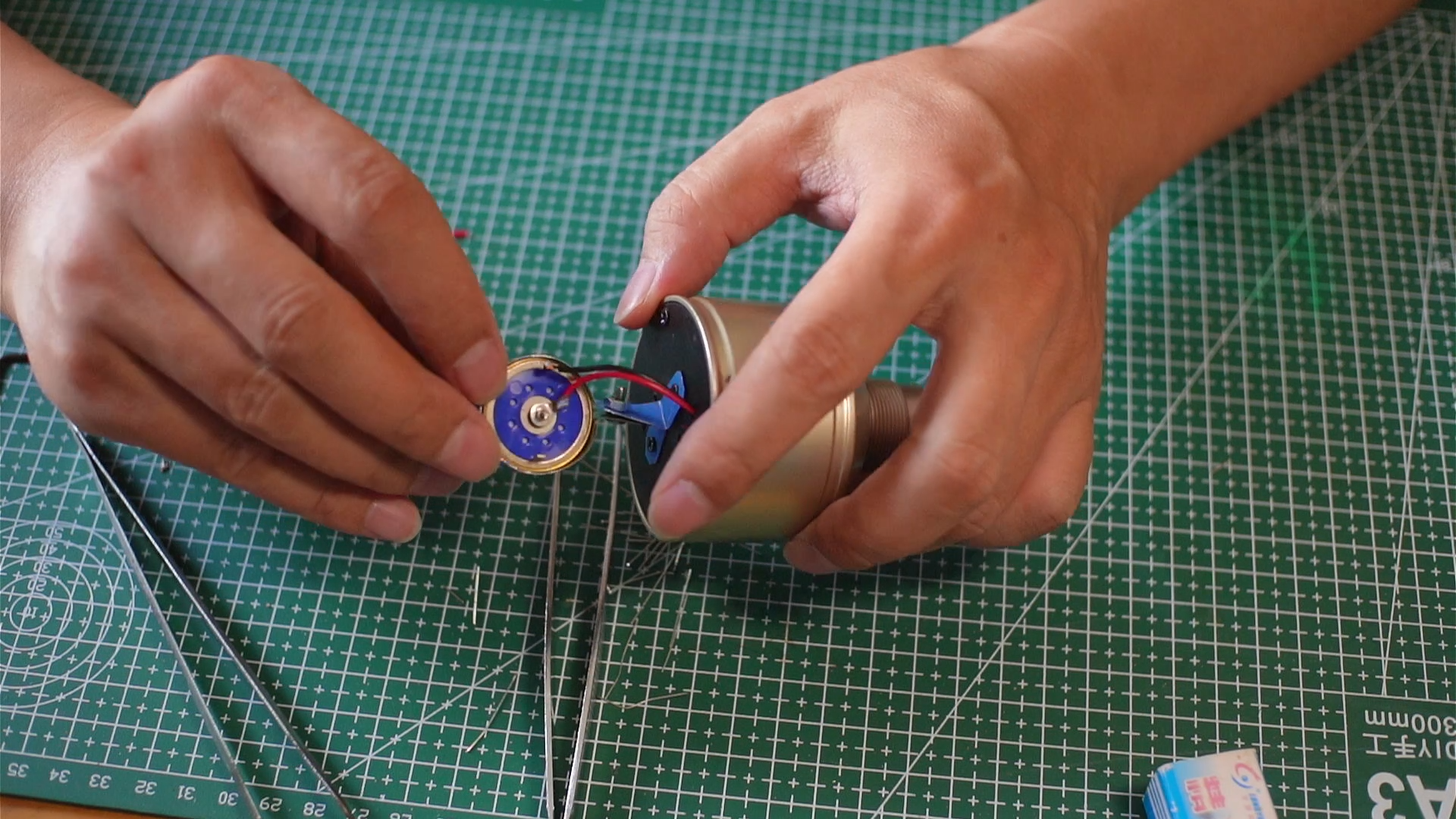
A tutorial video is available on Bilibili for reference:
DIY Large Diaphragm Microphone
https://www.bilibili.com/video/BV1QP411a7Ls/?spm_id_from=333.999.0.0
I didn't take photos of the tutorial video, only a few screenshots from the video.


PDF_48V Phantom Powered Microphone Circuit_Discrete Component Version Prototype Available.zip
Altium 48V phantom powered microphone circuit - discrete component version is available as a sample. (zip file)
PADS 48V Phantom Powered Microphone Circuit - Discrete Component Version Prototype Available (zip)
BOM_48V Phantom Powered Microphone Circuit_Discrete Component Version Prototype Available_2023-08-22.xlsx
94923
MMA8452 module
A low-cost gyroscope module
The MMA8452QR1 gyroscope module can replace the MPU6050 at a lower cost of less than 2 yuan. It can output three-axis angle and acceleration data via IIC interface communication and also has transient detection, motion detection, and sleep mode functions.
WeChat image_20240430181536.jpg
PDF_MMA8452 module.zip
Altium_MMA8452 module.zip
PADS_MMA8452 module.zip
BOM_MMA8452 module.xlsx
94925
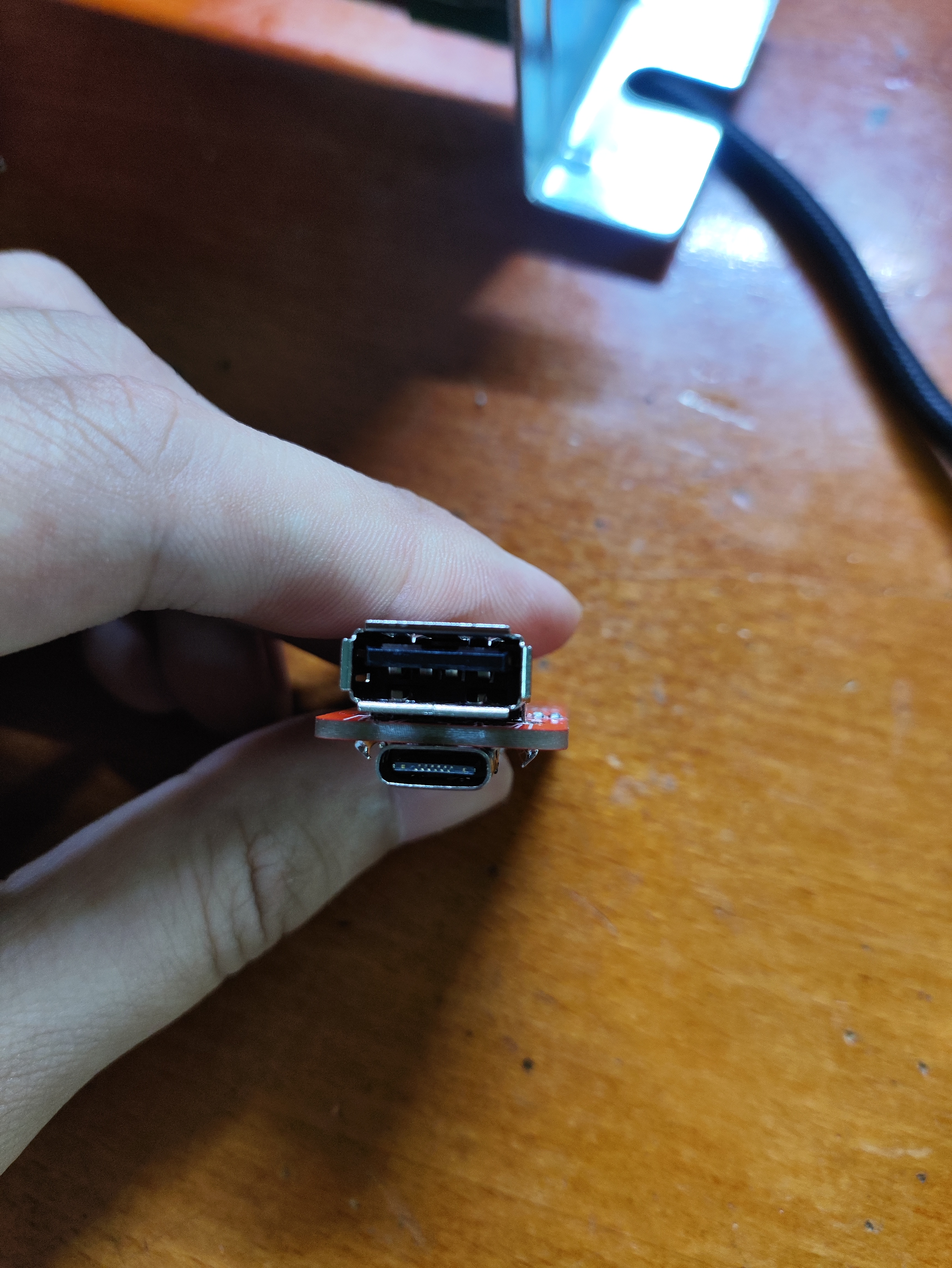
<Power Supply Project> Multi-Protocol Deceptive
It supports QC and PD3.0/2.0 protocols, with 5 adjustable output voltage levels from 5 to 20V, and theoretically supports an output power of up to 100W.
The design concept
involves creating a small, low-cost power supply device. The final choice was to use the CH224K chip as a decoy, along with a phone charger, to power other devices. Looking at other open-source projects using the CH224K, the single-resistor method only offered four voltage levels, while level configuration provides five.
The design is
a single-chip design using level configuration to output 5V, 9V, 12V, 15V, and 20V.
Both Type-C ports can be used as input/output ports simultaneously, and one USB-A port is for output only.
The overall cost is extremely low; the CH224K is only 1 RMB on Taobao. Only three DIP switches are used; a four-position switch would be even cheaper.
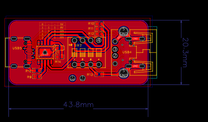

Note! The level configuration direction is reversed from the manual!
The original manual's method was somewhat unreasonable; pulling all switches low resulted in a default output of 9V.
When the switch is open, the default output is 5V.
The level configuration method is printed on the PCB.

Testing showed 5V,
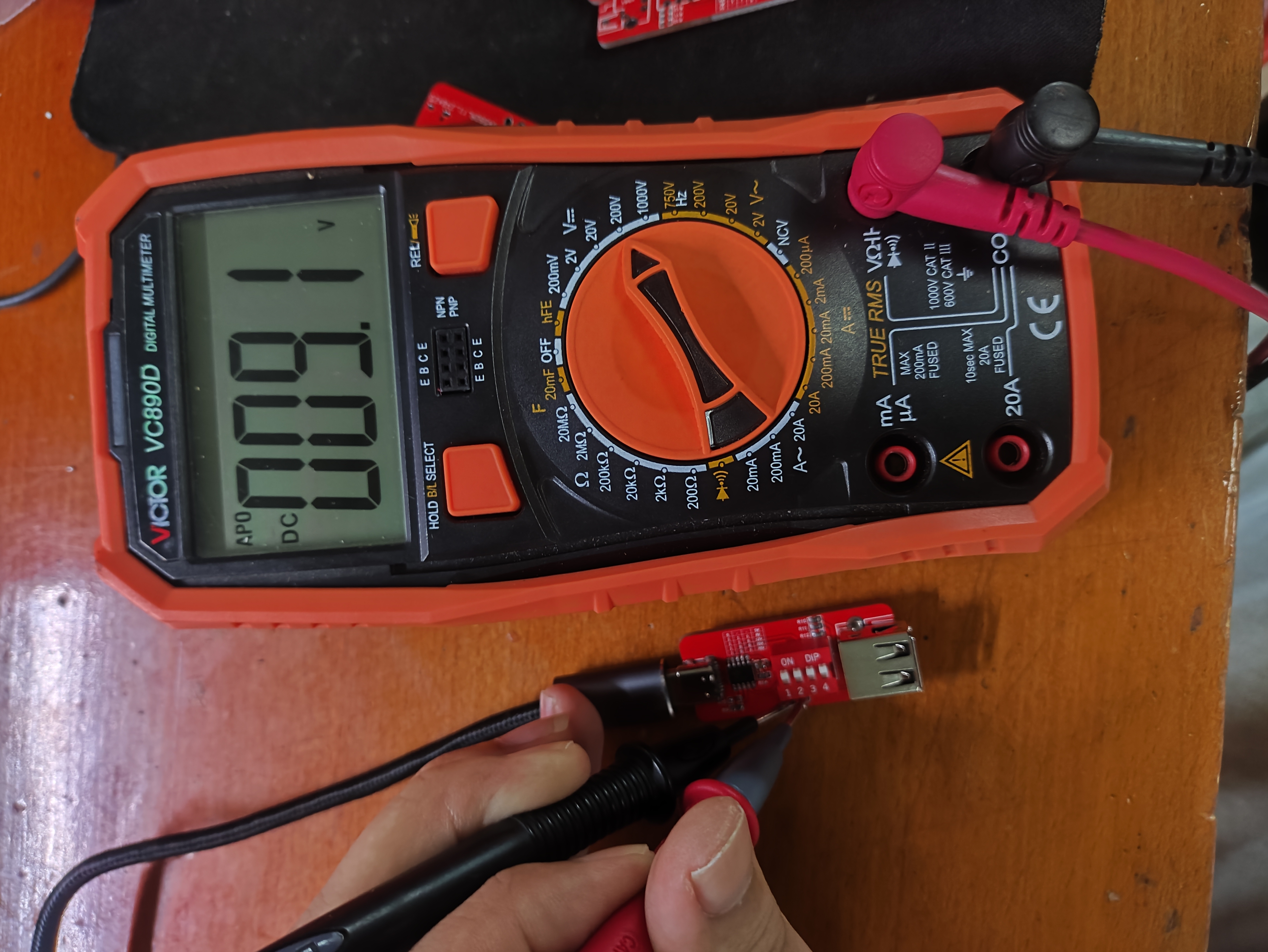
9V

, 12V
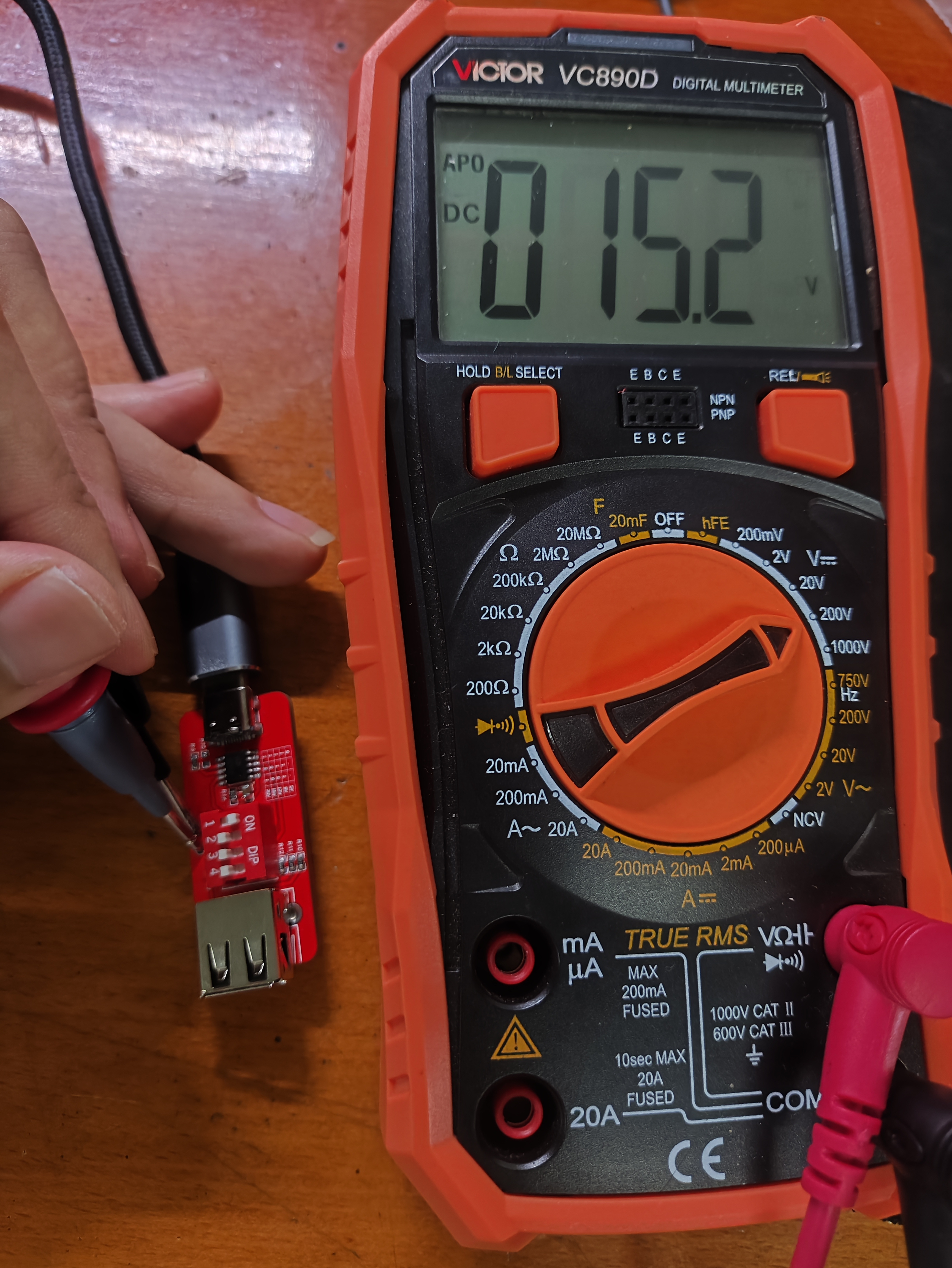
, 15V, and
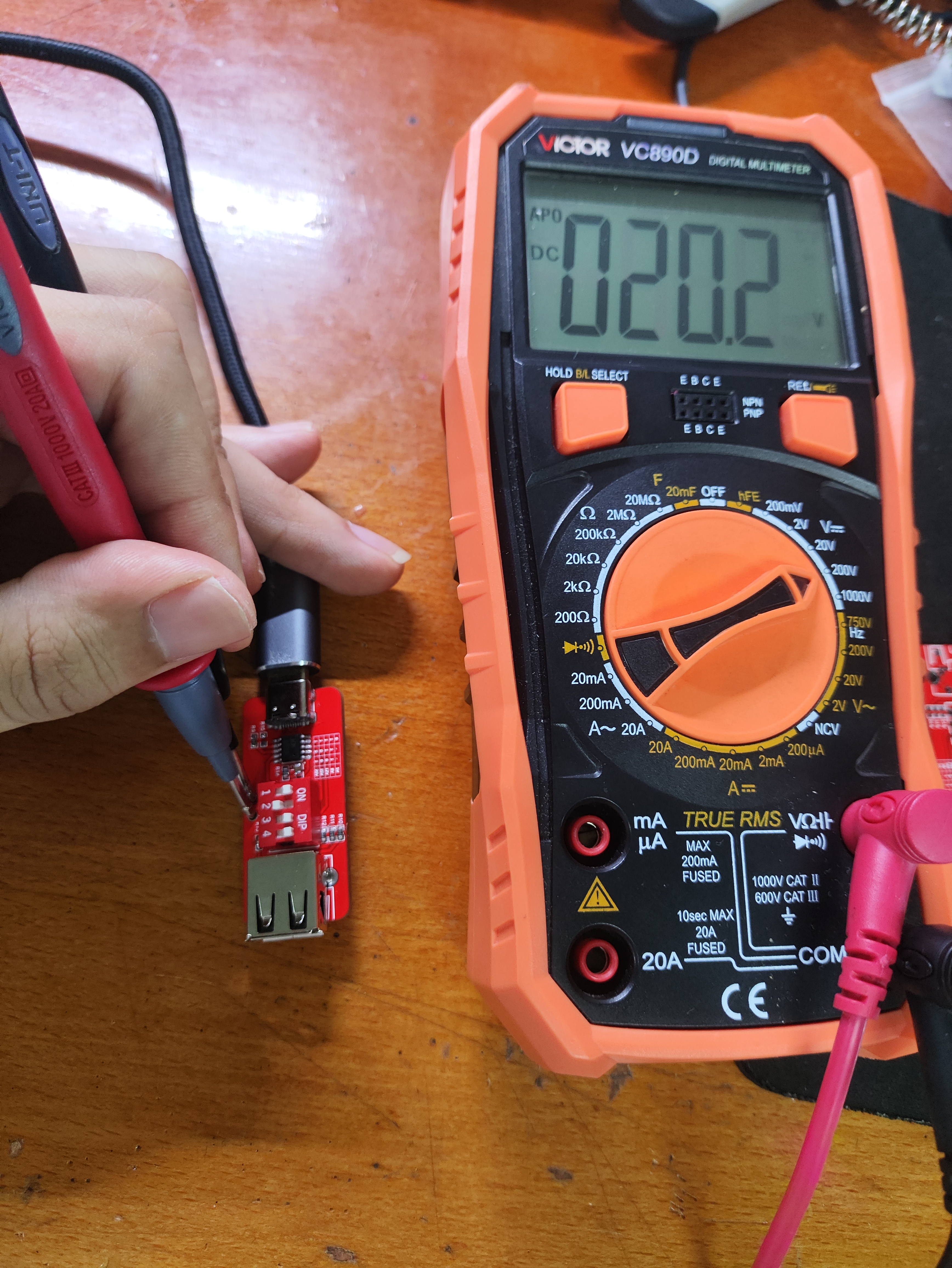
20V

reverse input.
PDF_<Power Project> Multiprotocol Deceptive.zip
Altium_<Power Project> Multiprotocol Deceptor.zip
PADS_<Power Project> Multiprotocol Deceptor.zip
BOM_<Power Supply Project> Multiprotocol Deceptive.xlsx
94927
ASR-PRO Core Board Cold Start Downloader
ASR-PRO Core Board Cold Start Downloader
ASR-PRO Core Board Cold Start Downloader
33e2eb867a685ea44912f9dac986475.jpg
PDF_ASR-PRO Core Board Cold Start Downloader.zip
Altium_ASR-PRO core board cold start downloader.zip
PADS_ASR-PRO Core Board Cold Start Downloader.zip
BOM_ASR-PRO Core Board Cold Start Downloader.xlsx
94928
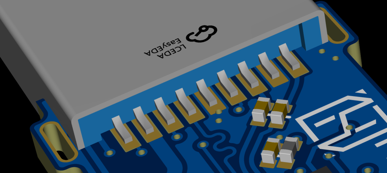
FC3379 QFN32 Minimum TSOP48 USB Flash Drive
The smallest TSOP48 single-chip USB flash drive based on FC3379 QFN32 (after all, it's only 1CE).
Why this project:
The FC3379, a new generation of "garbage king" (meaning it can run all sorts of bad games with decent speed), comes in three packages, the smallest of which, QFN32, only has 1CE channel.
The reason for this project was that I had some old junk chips on hand, and upon disassembling them, I found they were 1CE TSOP TLC NAND flash memory. With the help of my "thinking power," this project was born (?). (A BGA152 version will be released later (procrastination). Some details
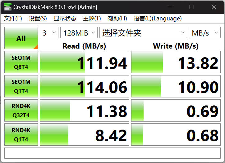
referenced from Lost-terminal's project : a double-layer board was used for faster prototyping and to avoid wasting 4-layer board resources (if it's free, cherish it). Because the USB reinforcement pins would interfere with the TSOP pads, the package was modified. When soldering, you need to bend it outwards a bit (for example, the silkscreen markings 3 and 2 on the board indicate VCC 3.3V and VCC 2.5V respectively). `v` is used to switch the VCC power supply of the NAND flash memory. An additional 0R resistor or wire connection is required. All other components can be removed from the original board. It's recommended to use TLC NAND flash if possible, as MLC NAND flash, according to LT, will significantly slow down speeds. (PS: The components are very cramped, which may cause considerable difficulty for those with less skill in soldering. Adding solder paste or using a hot plate may help.) You can also change the silkscreen to your preferred design, although there's not much space left. The speed is almost the same as the original board. (I don't know why the CDM write speed test is much slower than the actual speed.) Never use an ASSSD to run 4K, otherwise it will overload the 3379 firmware, causing a drastic speed drop, requiring a re-opening of the chip. The opening tool for the single-chip chip can be found on the official website: http://www.szfirstchip.com/col.jsp?id=142 FT64B08UCT2-08 (Jinshidun self-labeled Toshiba BICS5, single CE, 64G) full drive direct write speed is stable with no speed drop, occasionally fluctuating significantly. FT32B08CN1-47 (Jinshidun self-labeled B16A, single CE, 32G) full drive direct write speed is stable with no speed drop, almost a straight line (don't ask why the name is LostLabs because it was directly opened using LT's tools x).

PDF_FC3379 QFN32 Minimum TSOP48 USB Flash Drive.zip
Altium_FC3379 QFN32 Minimum TSOP48 USB Flash Drive.zip
PADS_FC3379 QFN32 Minimum TSOP48 USB Flash Drive.zip
BOM_FC3379 QFN32 Minimum TSOP48 USB Flash Drive.xlsx
94929
electronic


 京公网安备 11010802033920号

 BG050-10B-0-0450-0737-0350-N-E


