Part 1: Hardware
1.1 Main Control Unit
This project uses the CW32F030C8T6 Diwenxing minimum system board as the main control unit. The main control chip has a maximum clock frequency of 64MHz, 64KB FLASH, and 8KB RAM. A total of 26 I/O ports are used in this project: 14 pins for digital tube display, 3 pins for button control, and 4 pins for ADC conversion.

1.2 Power Supply Unit
1. This circuit uses an LDO as the power supply, selecting the SE8550K2 with a maximum input voltage of 40V. The main reason for not using a DC-DC step-down circuit to handle large voltage differences is to avoid introducing DC-DC ripple interference during the design process; a secondary reason is to reduce project costs.
2. The capacitors surrounding the LDO play an important role in filtering, improving load transient response, phase compensation, preventing oscillation, ripple suppression, and controlling startup surge current. By properly matching the external capacitors, the stability and performance of the entire circuit can be ensured.
3. Connecting a diode in series at the power input effectively prevents reverse power connection damage to key components. Connecting a 10Ω resistor in series for voltage division acts as a low-resistance fuse and reduces power-on surge peaks, effectively protecting downstream circuitry.

1.3
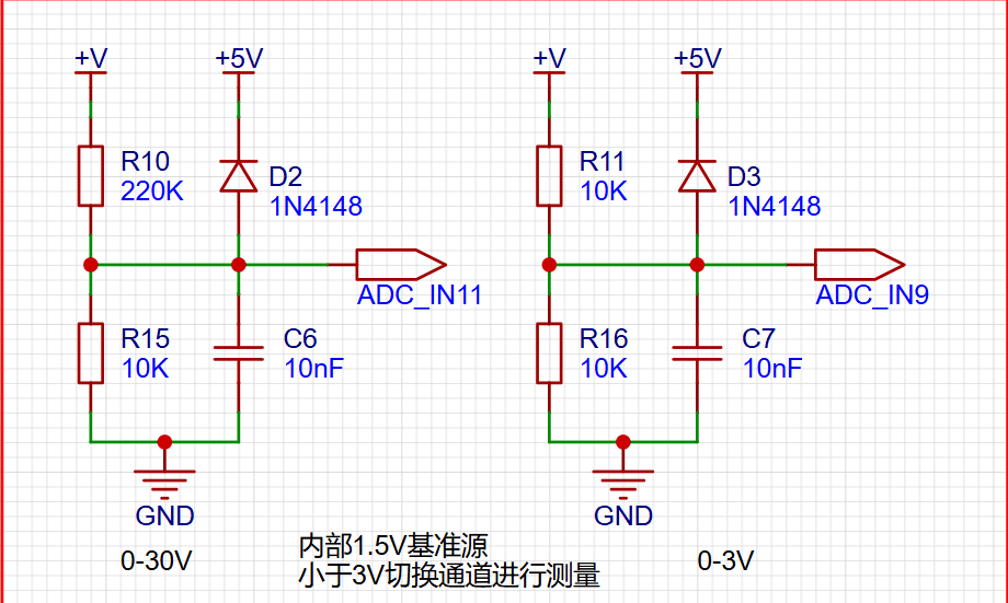
Selection of voltage divider resistor for voltage acquisition: The maximum voltage to be measured is 30V, and the ADC reference voltage is 1.5V. The calculated voltage division ratio is 1.5V/30V = 0.05. To reduce circuit power consumption, a 10K resistor is selected for the low-side side. Calculating 0.05 = 10kJ/(190K + 10K), the closest but greater standard resistor is selected as 220KJ.
Application of clamping diode: To protect the MCU from damage, an additional 1N4148 diode is added as a clamping diode. The forward conduction characteristic of the diode limits the voltage in the circuit to the forward voltage drop (typically 0.7V), achieving a protective function.
Measurement range switching introduces an additional voltage sampling circuit. This voltage sampling circuit uses the ADC_IN11 channel to measure voltages up to 30V. If the measured voltage is within the 0~3V range, the system will switch to the ADC_IN9 channel for measurement. Due to the reduced voltage division ratio, smaller voltage measurements can obtain more accurate values.
1.3 The current acquisition section
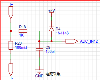
uses a low-side current sampling circuit for current detection. The low side of the sampling circuit shares a common ground with the development board's meter interface.
The maximum measured current is set to 3A, and the voltage drop across the current sensing resistor should not exceed 0.5V. Based on the power consumption and accuracy of the current sensing resistor, a 100mΩ 2512 surface mount resistor was selected. There is no amplifier circuit, so the actual multiplier is 1.
Calculations show that a 100mΩ current sensing resistor introduces a voltage of 300mV and consumes 900mW at 3A current.
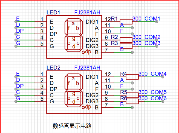
1.4 The digital tube display section
uses two 0.28-inch three-digit common-cathode digital tubes as display devices. Compared to a display screen, digital tubes have better recognition and are easier to identify in complex environments. Digital tubes have better mechanical properties and are less susceptible to damage from external forces. The size of the current-limiting resistor can be adjusted according to different environmental requirements to achieve higher brightness. In this project, the current-limiting resistors (R1~R6) for the digital tube are selected as 300Ω, which ensures good visibility and soft brightness.
II: Software Section 2.1 ADC Initialization
Code
is as follows. This code mainly completes the initialization configuration of the current channels ADCH_IN11 and ADCH_IN12. Configured with internal 1.5V as reference, using continuous sampling mode:
void ADC_init(void)
{
ADC_InitTypeDef ADC_InitStructure; // ADC configuration structure
ADC_SerialChTypeDef ADC_SerialChStructure; // ADC serial channel structure
GPIO_InitTypeDef GPIO_Init_Struct;
__RCC_GPIOB_CLK_ENABLE(); // Enable clock for corresponding ADC pins __RCC_ADC_CLK_ENABLE(); // Enable ADC clock
PB01_ANALOG_ENABLE(); // Enable analog pins
PB00_ANALOG_ENABLE(); // Enable analog pins
PB10_ANALOG_ENABLE(); // Enable analog pins
PB11_ANALOG_ENABLE();
ADC_StructInit(&ADC_InitStructure); // Initialize ADC default values
ADC_InitStructure.ADC_ClkDiv = ADC_Clk_Div128; // Configure ADC operating clock PCLK/4 = 6/4 = 1.5MHz
/* When the signal voltage is low, the reference voltage can be reduced to improve resolution. After changing the reference voltage, the same binary representation of the voltage value will be different.
The largest binary value (all 1s) represents your reference voltage, and the reference voltage needs to be taken into account when calculating the actual voltage. */ /*
ADC_InitStructure.ADC_VrefSel = ADC_Vref_BGR1p5; // Set the reference voltage to 1.5V
ADC_InitStructure.ADC_SampleTime = ADC_SampTime10Clk; // Since the voltage signal is a slow signal, the ADC sampling time is ten ADC sampling cycles to ensure accuracy
ADC_SerialChStructure.ADC_Sqr0Chmux = ADC_SqrCh11; // Configure the ADC sequence, PB01 is the 9th channel of the ADC
ADC_SerialChStructure.ADC_Sqr1Chmux = ADC_SqrCh12;
ADC_SerialChStructure.ADC_SqrEns = ADC_SqrEns01;
ADC_SerialChStructure.ADC_InitStruct = ADC_InitStructure; // Initialize the ADC
ADC_SerialChContinuousModeCfg(&ADC_SerialChStructure); //Configure ADC sequence continuous conversion mode
ADC_ClearITPendingAll(); //Clear all ADC interrupt states
ADC_Enable(); // Enable ADC
ADC_SoftwareStartConvCmd(ENABLE); // ADC conversion software startup command
}
2.2 ADC voltage and current calculations are as follows. Where, Volt_Buffer is the acquired voltage channel code value, or the calculated voltage value, with voltage in units of 10mV. Current is calculated by passing through a 0.1R resistor.
void Volt_Cal(void)
{
float t,KT1;
V_Buffer = Mean_Value_Filter(Volt_Buffer,ADC_SAMPLE_SIZE);//Use mean filtering
I_Buffer = Mean_Value_Filter(Curr_Buffer,ADC_SAMPLE_SIZE); //Use mean filtering
V_Buffer = (V_Buffer * ADC_REF_VALUE >> 12) * (R2 + R1)/R1;
// Rounding
if(V_Buffer % 10 >= 5)
{
V_Buffer = V_Buffer / 10 + 1;
}
else
{
V_Buffer = V_Buffer / 10;
}
ADC_GetSqr1Result(&I_Buffer); ///Display the current acquired value
I_Buffer=I_Buffer * ADC_REF_VALUE >> 12;
/**mv =I_Buffer * ADC_REF_VALUE >> 12,
R = 100mr,
10ma = mv/R/10=mv/0.1/10 = mv
*/
}
2.3 The main program is as follows
int main()
{
RCC_Configuration(); //System clock 64M
KEYGPIO_Init();
GPIO_WritePin(CW_GPIOC,GPIO_PIN_13,GPIO_Pin_RESET);
Seg_Init();
Btim1_Init();
ADC_init();
while(1)
{
if(BrushFlag==1)
{
Display(V_Buffer);
DisplayI(I_Buffer);
BrushFlag=0;
}
if(timecount>= 300) //Change the digital tube display value once every 300ms//
{
timecount=0;
Volt_Cal();
BrushFlag=1;
}
}
}
Three: Physical verification part
VID_20240824_150410.mp4
VID_20240824_164018.mp4


 京公网安备 11010802033920号

 180-071NF42


