I. Function Introduction
This device currently has three buttons: Switch, Set, and Return. It has five operating modes as follows:
1. Displaying normal voltage and current values (the left digital tube displays the voltage value, and the right displays the current value)
. 2. Setting the 5V voltage calibration value. The left digital tube displays 5.05. The right displays the current voltage value. In this mode, the multimeter should be set to 5.00V. After pressing the Set button, the current value will be calibrated to 5V.
3. Setting the 15V voltage calibration value. The left digital tube displays 5.15. The right displays the current voltage value. In this mode, the multimeter should be set to 15.0V. After pressing the Set button, the current value will be calibrated to 15V.
4. Setting the 5A current calibration value. The left digital tube displays A.0.5. The right displays the current current value. After pressing the Set button, the current value will be calibrated to 0.5A.
5. Current 5A calibration setting. The left-hand digital display shows A.1.5. The right-hand display shows the current current value. Pressing the setting button calibrates the current value to 1.5A.
II. Hardware Design
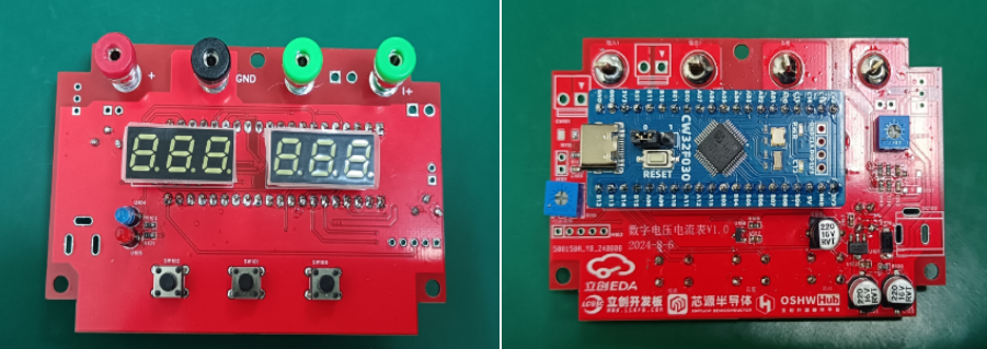
The device uses the LCSC CW32F030C8T6 development board as the main controller to develop a digital voltmeter and ammeter. The following is a description of part of the circuit: For details, please refer to the training camp project materials: https://wiki.lckfb.com/zh-hans/dwx-cw32f030c8t6/
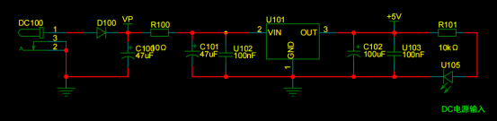
1. Power Supply Circuit
The core board is powered by 5V, so only a 5V output power supply circuit is needed. An external DC plug is used for power supply, and a diode is used for reverse connection protection. A 10K resistor is connected in series to reduce the problem of severe overheating caused by the large voltage difference of the LDO under high voltage conditions. On the other hand, the 10-ohm low-power resistor in series acts as a low-resistance fuse, providing overcurrent protection or short-circuit protection. The SE8550K2-HF power supply, with a wide input voltage, was selected, capable of handling a maximum input voltage of 40V. The LED lights up after outputting 5V.
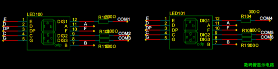
2. The digital tube circuit
uses two 0.28-inch three-digit common-cathode digital tubes as display devices. Six current-limiting resistors placed on the digit selection pins are sufficient to ensure the tubes light up without being glaring.
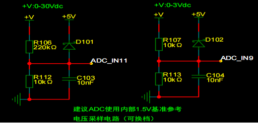
3. The voltage sampling circuit
uses a voltage divider circuit to achieve high voltage acquisition. Currently, it can acquire 0-30V/0-3V.
The value of R106 is calculated through the internal reference voltage
. 1. Calculate the required voltage division ratio: 5V/30V = 0.05 using known parameters.
2. Calculate the R106 resistance: i.e., R112 resistance / voltage division ratio. 10K/0.05 = 200K using known parameters.
3. Generally, a resistor close to 200K is chosen .
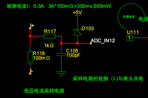
4. The current sampling circuit
uses a 100mΩ current sensing resistor. According to the formula, 3A * 100mΩ = 300mV, 900mW can be calculated.
To cope with different usage environments, especially high current scenarios, the R118 resistor can be replaced with constantan wire or a shunt. The replacement can be chosen according to the actual usage scenario.
III. Software Code
To maintain the consistency between the digital tube and the printed characters on the membrane, only the corresponding pins were modified in the source code.
IV. Other Materials
| No. |
Name |
Quantity |
Description | |---|---|---|---| |
1.
Top Cover |
1 |
| 2.
Bottom Cover
| 1 |
| 3.
Film |
1
| | 4.
M3*6 Screws
| 3
| | 5.
M3*12 Self-Tapping Screws |
4 | V.
Assembly Steps
| The overall assembly diagram is shown below:

| 1. After soldering the circuit board, power on and download the code, as shown below: |
2. Place it in the top cover and tighten the screws. I used wire bonding for the DC plug, as shown below: |

3. Three types of film were designed, as shown below:

| 4. Apply the film and install the bottom cover, as shown below:

| VI. Demonstration Video


 京公网安备 11010802033920号

 ASM5I2308AG-3-16-SR


