Dear friends, welcome to the Open Source Project. Before reading, please be sure to read the following disclaimers. 1. Disclaimer: I am not a professional electronics engineer or technician. This project description is merely a demonstration and sharing of the production process, intended for exchange and learning among enthusiasts. It is not a tutorial. If you wish to imitate the content in this project description, you must bear all risks and responsibilities yourself.
2. Professional Advice: It is strongly recommended that you supplement your professional knowledge and seek professional advice and guidance before making and using any DIY electronic devices to ensure you have sufficient technical knowledge and experience.
3. Caution: Please operate in a safe environment and ensure you understand and follow relevant safety guidelines. Incorrect operation may lead to serious safety risks, including but not limited to electric shock, fire, etc.
4. Individual Differences: I cannot guarantee that the operations, designs, and data appearing in the project description are completely correct. Your electronic devices and materials may differ from those used in this project description, therefore the results may differ. When implementing this solution, please consider the specificities of your individual equipment and materials.
5. Scope of Disclaimer: The author of this project description is not responsible for any loss, damage, or accident caused by imitating this project description. Please read and understand all contents of this disclaimer carefully before starting. By viewing this project description, you agree to and accept the above disclaimer. If you have any doubts about the DIY process, it is recommended that you consult a professional. Thank you for your understanding and cooperation. Many fans use a booster cable + power bank to solve dormitory network outages at night. The advantage is that the booster cable is very cheap
(around
10 yuan), but the disadvantage is that the power bank needs to wait a few seconds to switch. The power
bank is plugged in to charge during the day, but its output is connected to this module. After the power outage at night, the relay switches to power from the power bank, but the power bank needs 5-10 seconds to switch. Use an 18650 battery to replace it. This battery doesn't need to be high quality; a cheap one from Pinduoduo (around 2-3 yuan with free shipping) will do. After the power bank switches, use the power bank to power the module.
Note!
① Some routers are 9V, but the BOM list shows a 12V relay. If the router is 9V, select 9V when choosing the relay.
② This assumes you already have a USB 12V boost cable. This cable is not listed in the BOM. If you don't have it, please purchase it separately. (If your power bank can output 12V, a decoy cable is preferable.)
③ Some routers (such as Xiaomi) do not have a 5.5V DC port; you will need to purchase the corresponding cable or adapter.
④ This UPS motherboard only supports 3.7-4.2V batteries. When purchasing batteries and battery boxes, be sure to avoid buying batteries and battery boxes connected in series!
⑤ For the voltage display, please buy one with a range of 0-100V, covering 3.7-4.2V. Do not buy those with a range of 4-30V.
Please refer to the BOM parts in the attached table for
the schematic diagram:

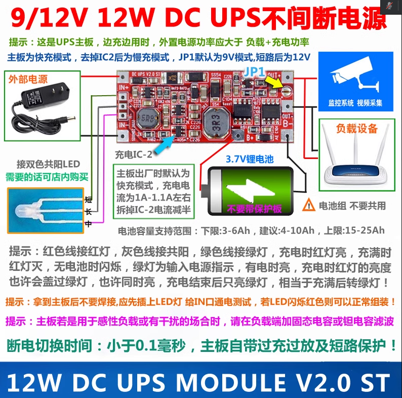
UPS Module Introduction (Purchased Finished Product):
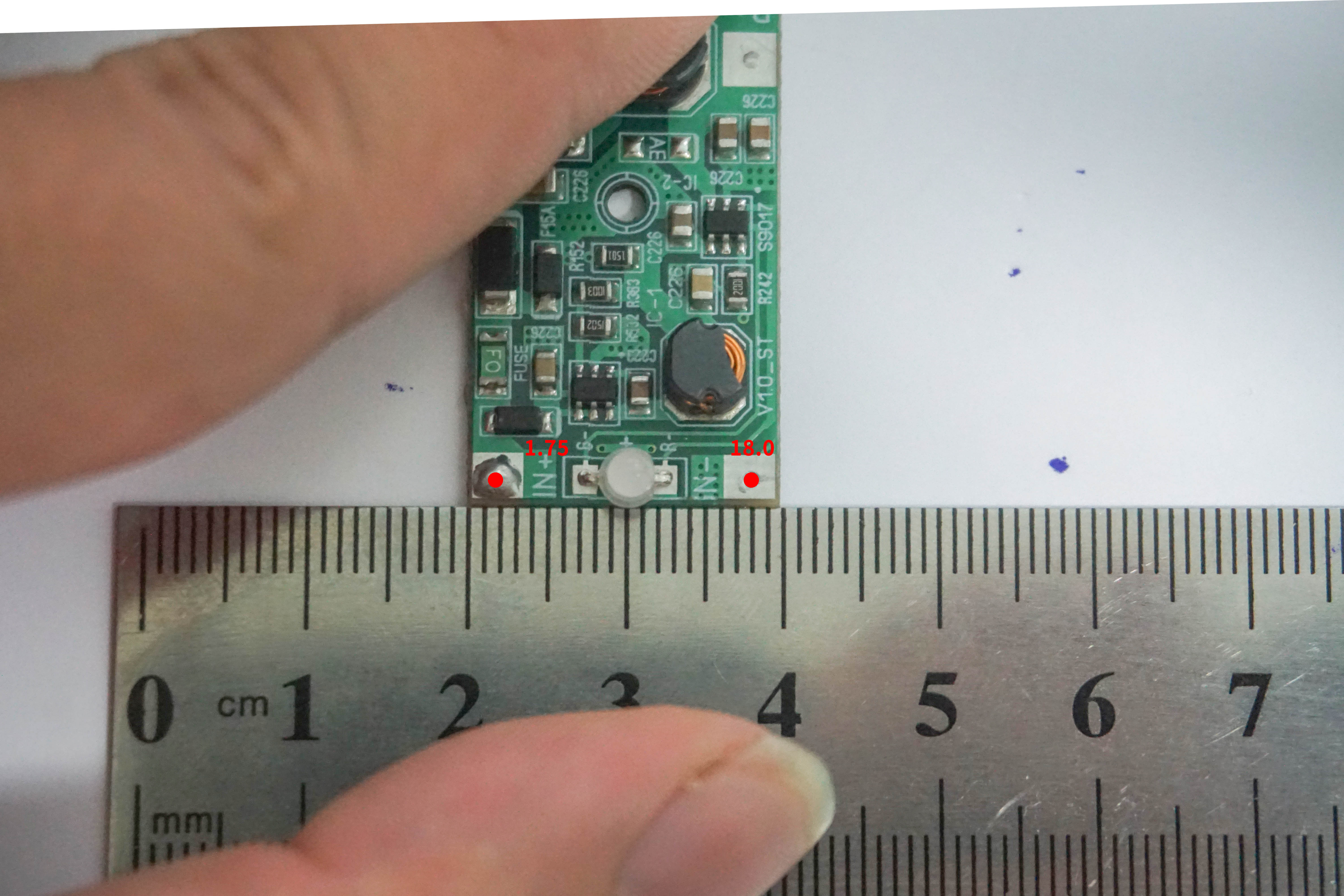
Dimensions:

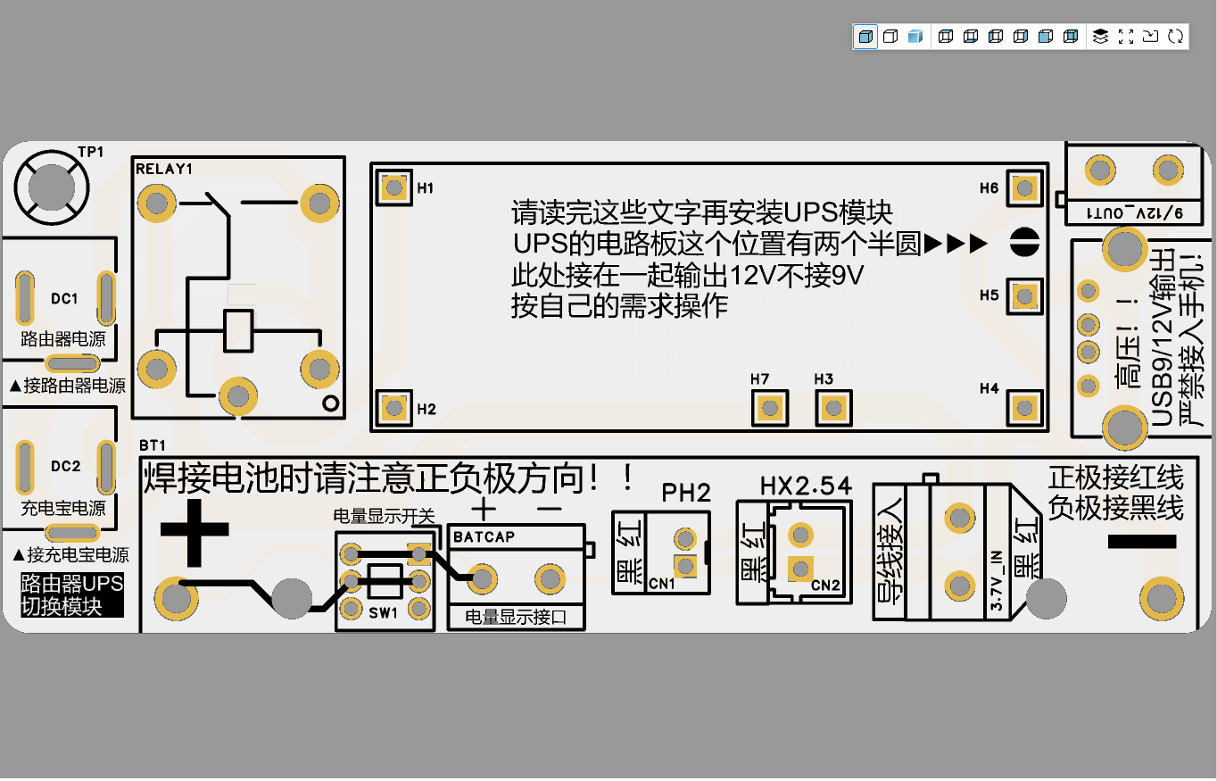
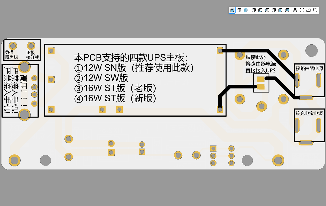
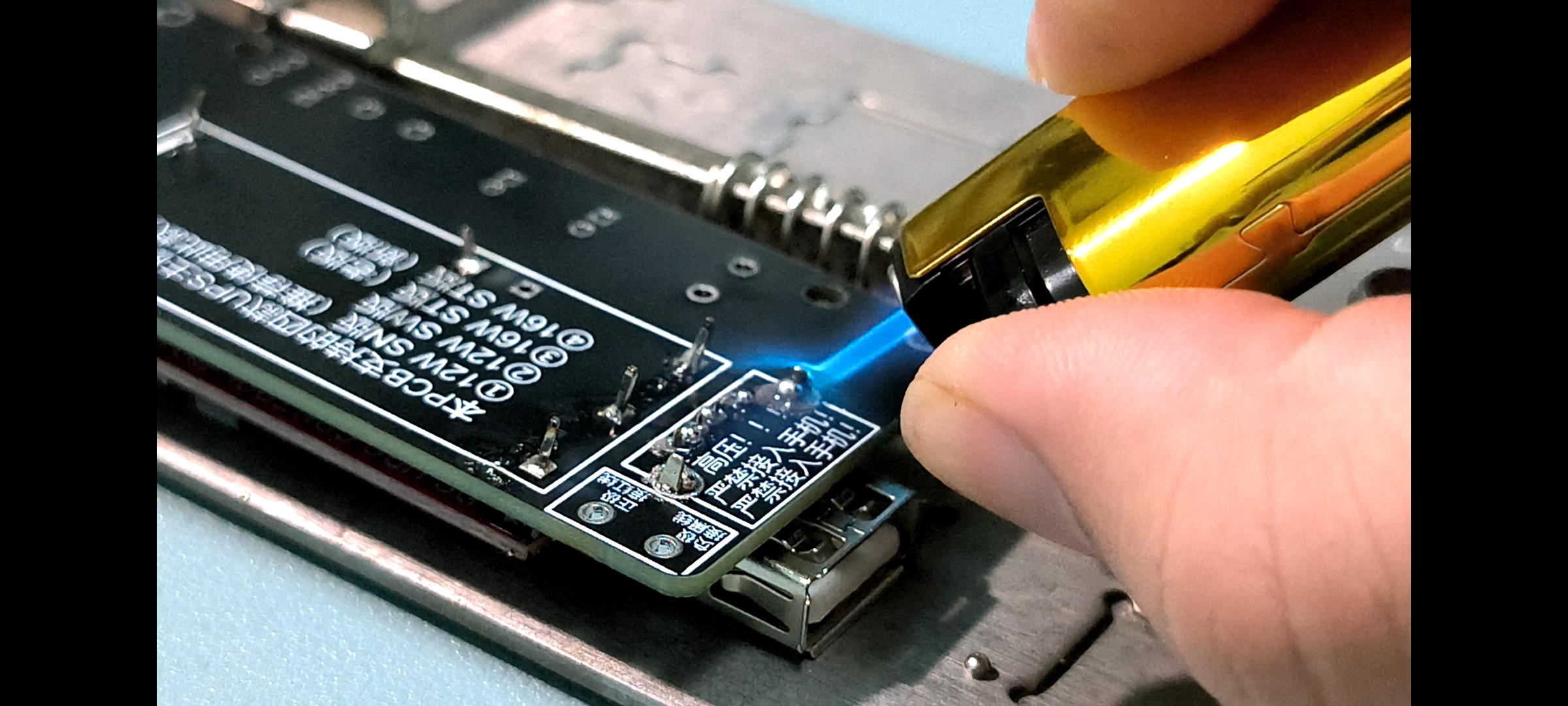
PCB Appearance:
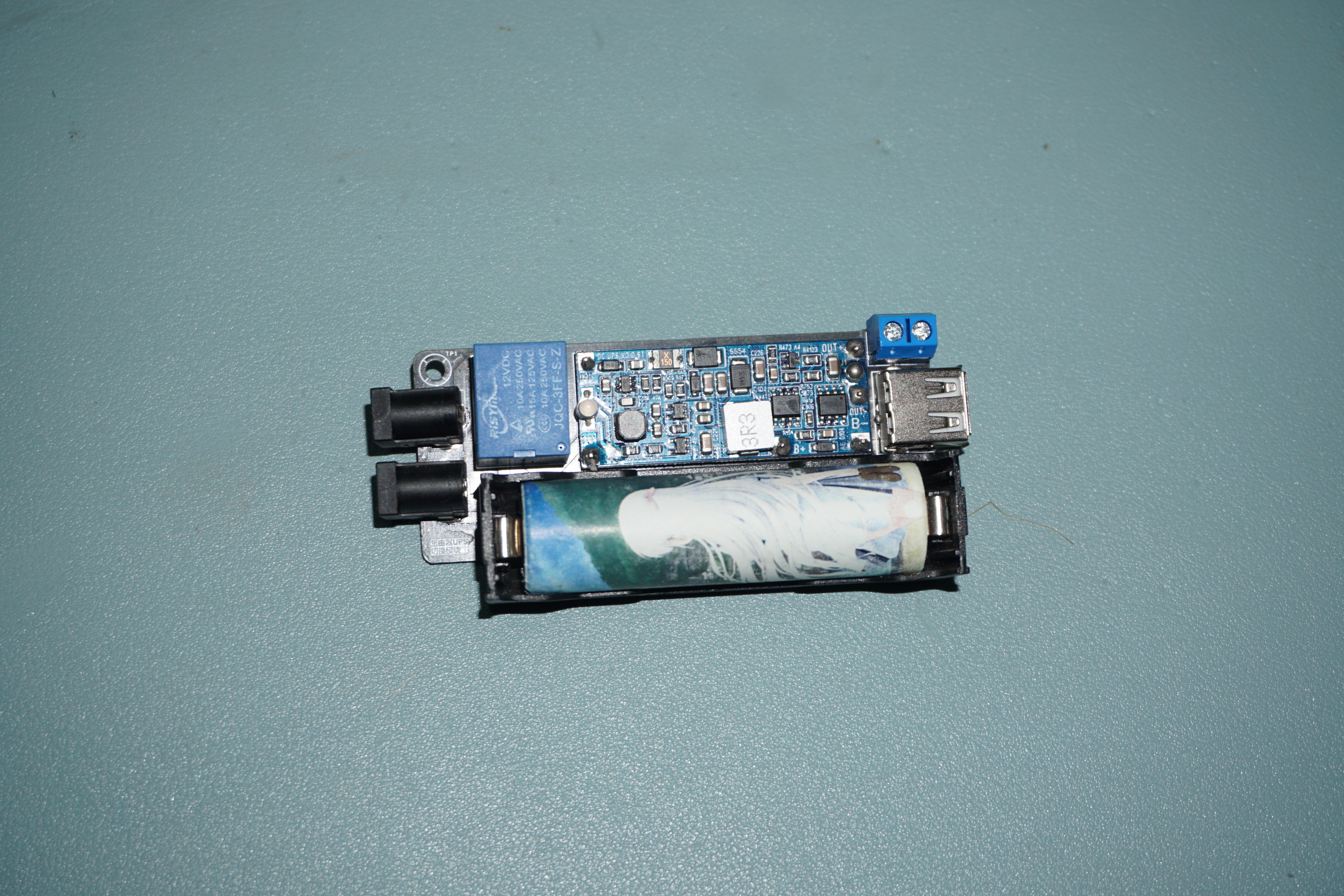
Actual Photo:

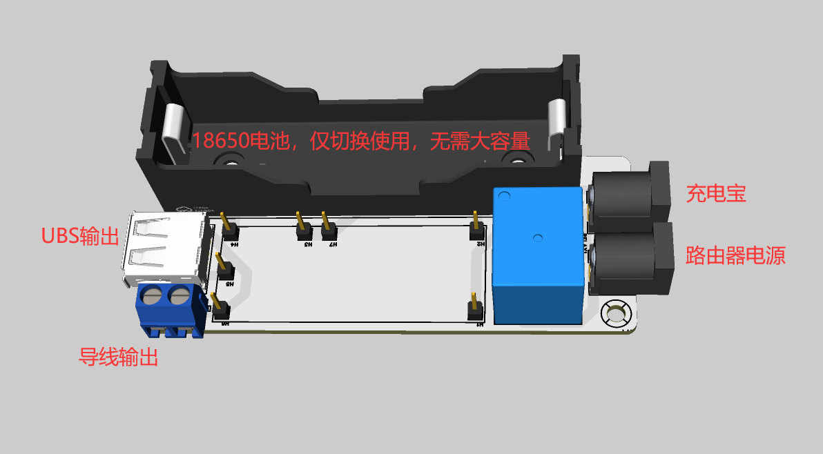
Connection Method:
In the image below, the connection between the power bank and the UPS switching board is a boost cable or decoy cable, not a regular USB to DC 5V converter!

——————————————————————————————————————————————————————————
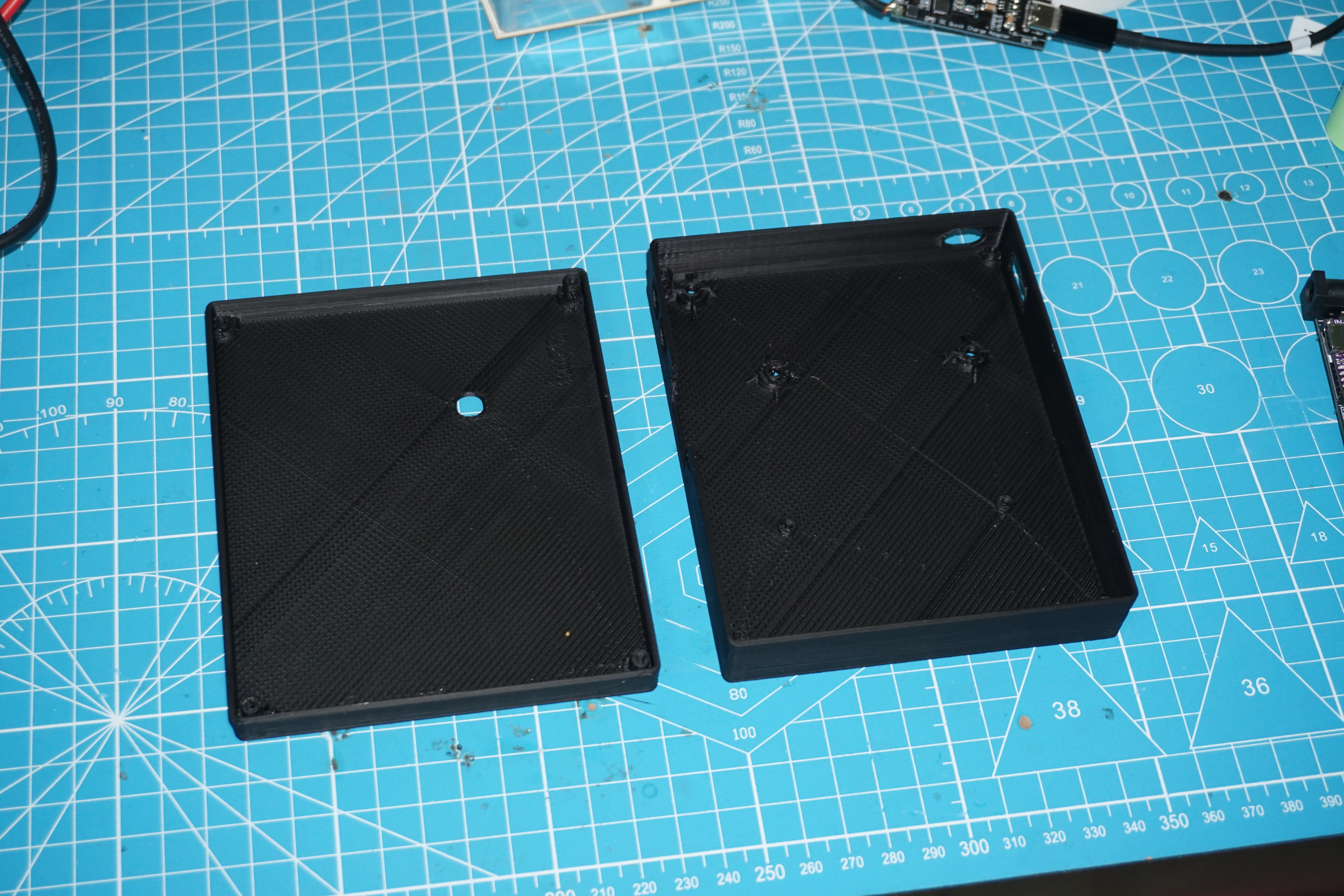
I didn't expect it to actually break 50,000! I gritted my teeth and finished the outer shell in one day. I had to model it and make a prototype for verification. It's usable, but definitely not aesthetically pleasing.

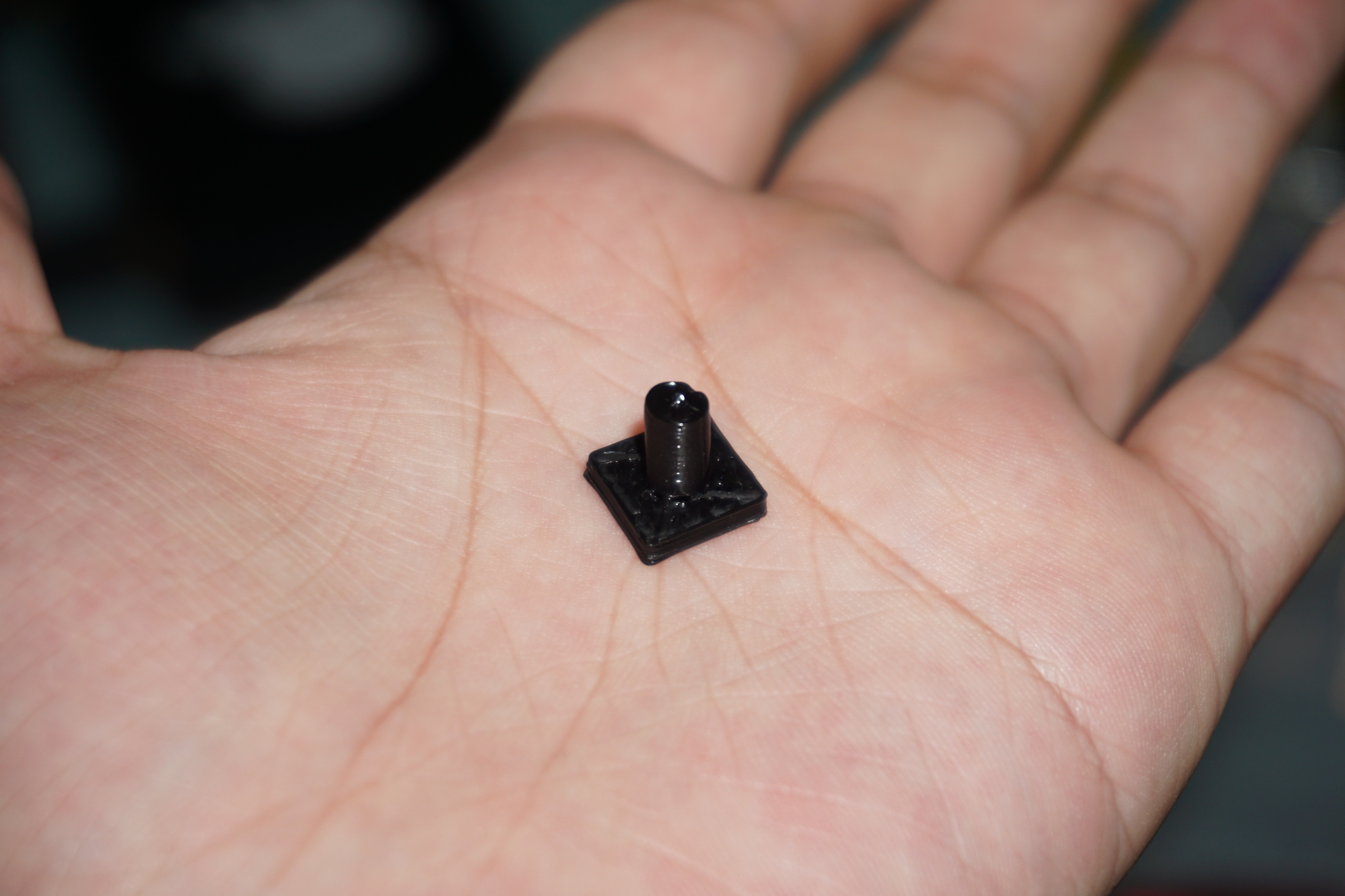
3D printed physical image:
Assembly:
Required screws and nuts:
[3] M3 screws 8mm
[3] M3 nuts
[2] M2 screws 6mm
[2] M2 nuts
[8] M2 screws 12mm
[4] M2 copper pillars 11mm

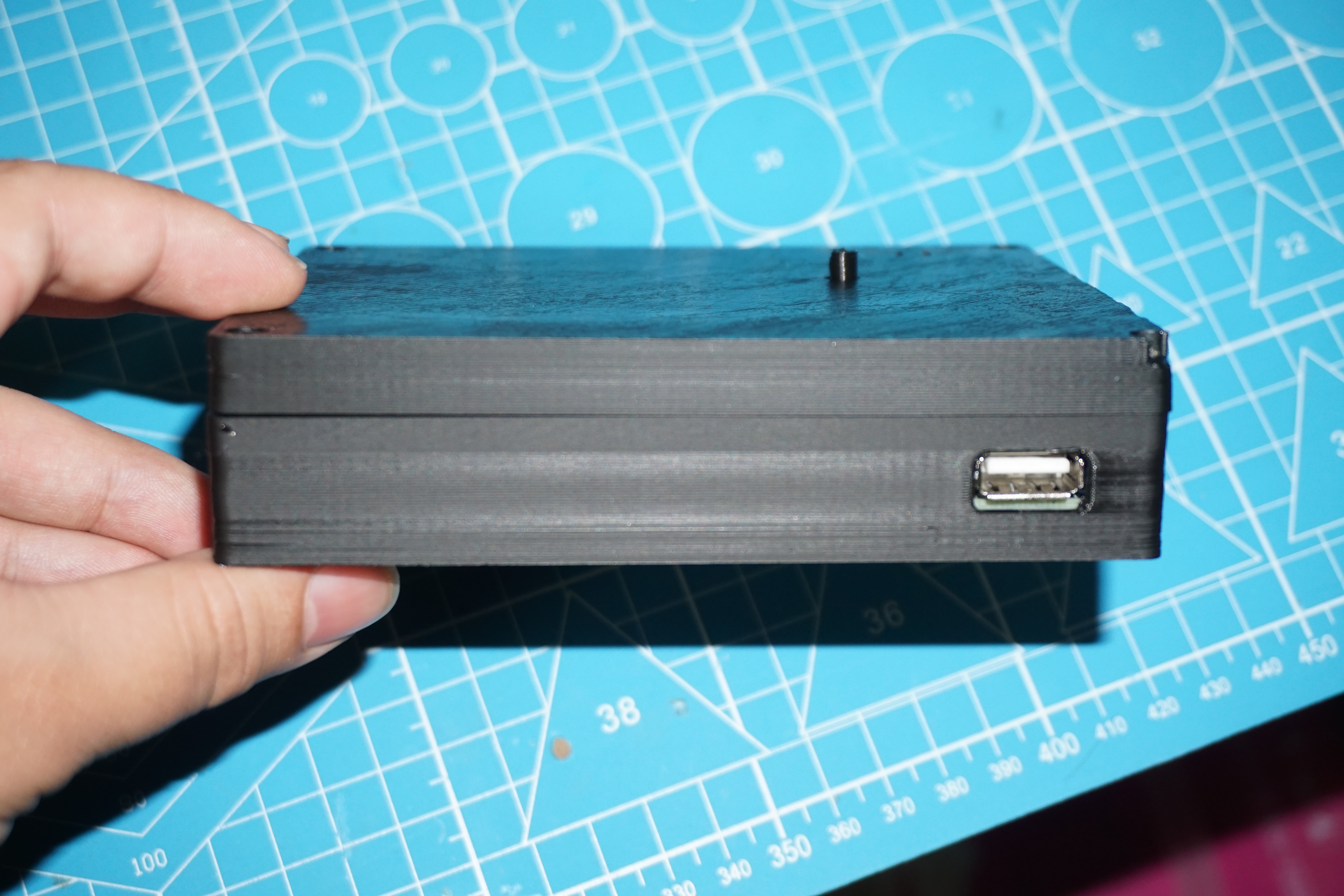
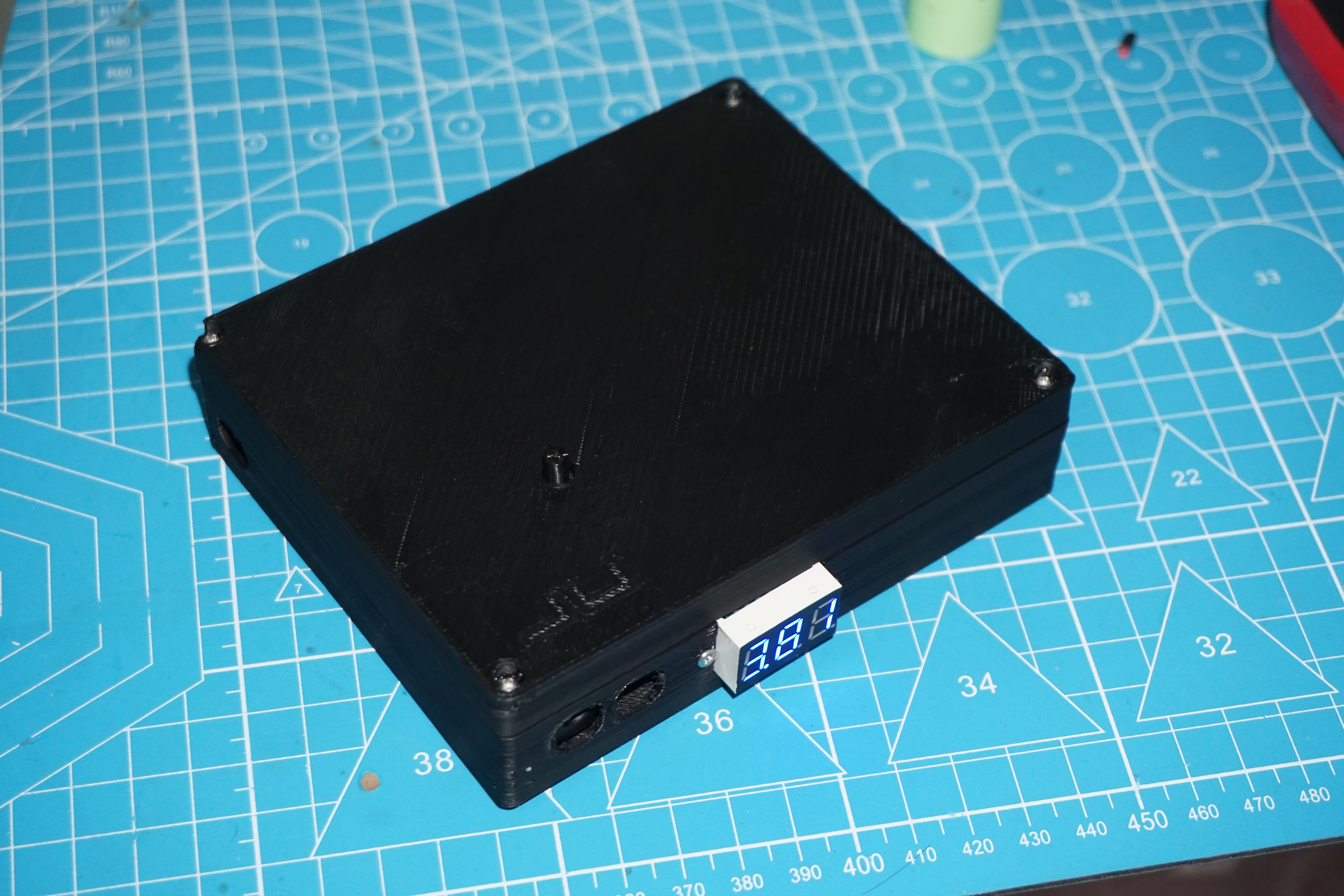
Finished product


 京公网安备 11010802033920号

 288VD32F321A1


