Output large current regulated voltage adjustable power supply, 3~15V 10A adjustable regulated voltage power supply circuit diagram
Source: InternetPublisher:三岁就很酷 Keywords: Regulated power supply adjustable power supply circuit Updated: 2025/03/07
10A adjustable voltage regulated power supply circuit diagram (I)
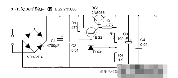
Low-voltage, high-current regulated DC power supplies are often used in electronic experiments. The output voltage of this circuit is continuously adjustable from 3V to 15V, and the maximum load current can reach 10A.
10A adjustable voltage regulated power supply circuit diagram (II)
The following is a voltage-stabilized power supply with a continuously adjustable DC voltage from 3V to 15V and a maximum current of 10A. The circuit uses the high-precision standard voltage source integrated circuit TL431 with temperature compensation characteristics to make the voltage regulation more accurate. If there are no special requirements, it can basically meet normal maintenance needs. The circuit is shown in the figure below.
As shown in the figure, the circuit diagram of high-power adjustable voltage-regulated power supply:

Working principle:
Its working principle is divided into two parts. The first part is a fixed 5V1.5A voltage-stabilized power supply circuit. The second part is another high-precision high-current voltage-stabilized circuit with a continuously adjustable voltage from 3 to 15V.
The first circuit is very simple. The 8V AC voltage from the transformer secondary is rectified by the silicon bridge QL1, and then filtered by the C1 electrolytic capacitor. The 5V three-terminal voltage regulator LM7805 can generate a fixed 5V1A regulated power supply at the output end without any adjustment. This power supply can be used as an internal power supply when repairing the computer board.
The second part is basically the same as the ordinary series-type voltage-stabilized power supply, except that it uses a high-precision standard voltage source integrated circuit TL431 with temperature compensation characteristics, so the circuit is simplified, the cost is reduced, and the voltage-stabilizing performance is very high. In the figure, the resistor R4, the voltage-stabilizing tube TL431, and the potentiometer R3 form a continuously adjustable constant voltage source to provide a reference voltage for the base of BG2. The voltage-stabilizing value of the voltage-stabilizing tube TL431 is continuously adjustable, and this voltage-stabilizing value determines the maximum output voltage of the voltage-stabilized power supply. If you want to expand the adjustable voltage range, you can change the resistance values of R4 and R3. Of course, the secondary voltage of the transformer should also be increased. The power of the transformer can be flexibly controlled according to the output current, and the secondary voltage is about 15V. The rectifier tube QL used for bridge rectification uses a 15-20A silicon bridge, which has a compact structure and a fixing screw in the middle. It can be directly fixed on the aluminum plate of the casing, which is conducive to heat dissipation. The adjustment tube uses a high-current NPN metal shell silicon tube. Due to its high heat generation, if the chassis allows, try to buy a large heat sink to expand the heat dissipation area. If you don't need a large current, you can also use a silicon tube with a smaller power, so that the volume can be smaller. The 50V4700uF electrolytic capacitors C5 and C7 used for filtering are connected in parallel with three of each other to make the large current output more stable. In addition, this capacitor should be bought with a relatively large volume. Those with smaller volumes and the same 50V4700uF should be avoided as much as possible. When the voltage fluctuates frequently or is not used for a long time, it is easy to fail. Finally, let's talk about the power transformer. If you don't have the ability to wind it yourself, or you can't buy a ready-made one, you can buy a ready-made switching power supply of more than 200W instead of the transformer. In this way, the voltage stabilization performance can be further improved, but the production cost is not much different. There are no special requirements for other electronic components. After installation, it can work normally without much adjustment.
- Overvoltage detection circuit schematic, overvoltage detection circuit analysis
- The working principle of electronic fuses and how to use them
- What effect does the copper coating on the bottom of the inductor have on the power supply?
- How to Make a Soft Latch Circuit
- 220V Remote Load Monitor
- Practical and convenient fax machine power supply control circuit
- Constant current LED lamp driver circuit with soft start and anti-shock
- Parallel DC regulated power supply circuit diagram
- Low cost and high performance LED constant current power supply
- Boost drive circuit composed of RT8450
- Computer motherboard power circuit with +5.1V, -5V, +12V and -12V outputs
- Class A power amplifier power circuit
- Karaoke light controller circuit (1)
- ±15V active servo power circuit
- Neon light high voltage power supply circuit
- Common power circuits and applications 09
- Common power circuits and applications 08
- Common power circuits and applications 03
- Common power circuits and applications 01
- ±5V, ±12V power circuit B


 京公网安备 11010802033920号