Overvoltage detection circuit schematic, overvoltage detection circuit analysis
Source: InternetPublisher:newlandmark Keywords: Detection circuit overvoltage Updated: 2025/03/07
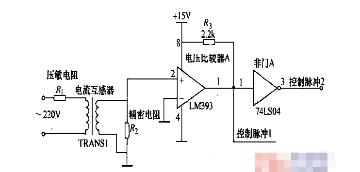
Overvoltage detection circuit schematic
The schematic diagram of the overvoltage detection circuit is shown in the figure. When an overvoltage signal is generated, the varistor is broken down, presenting a low resistance value or even close to a short-circuit state, so that a large current is generated on the primary side of the current transformer, and a small current is generated on the secondary side through the mutual inductance of the coil, and then the current signal is converted into a voltage signal through a precision resistor; after this signal is input to the voltage comparator LM393, the voltage comparator LM393 outputs a high level, and the control pulse 1 output by the NOT gate A controls the power supply circuit, disconnects the switch power supply circuit, and starts the backup power supply. Control pulse 2 is sent to the interrupt of the microcontroller, and the microcontroller control circuit starts the A/D conversion and samples the instantaneous value of the overvoltage.
Overvoltage detection circuit (I)
D19 is a voltage-stabilizing diode. When the input voltage VIN is greater than (Vz+0.7)V, IO_IN changes from a high level to a low level, which can be easily detected using the GPIO interrupt of the MCU.

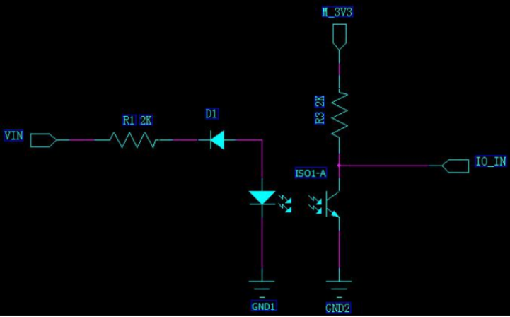
Overvoltage detection circuit (II)
Optocoupler is used for isolation detection. D1 is a voltage-stabilizing diode. When the input voltage VIN is greater than (VZ+VF), the optocoupler is turned on. VF is the turn-on voltage drop of the primary-side light-emitting diode of the optocoupler. IO_IN changes from a high level to a low level. The isolation detection can be easily realized by using the GPIO interrupt of the MCU.
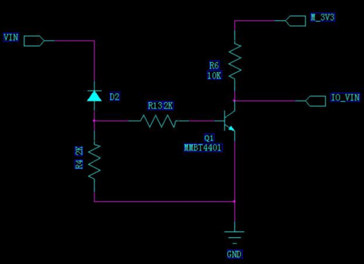
Overvoltage detection circuit (III)
D2 is a voltage-stabilizing diode. When the input voltage VIN is greater than (Vz+0.7)V, IO_VIN changes from high level to low level, which can be easily detected by the GPIO interrupt pin of the MCU.
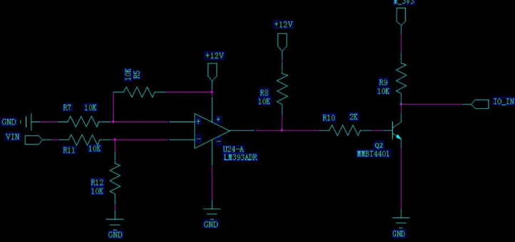
Overvoltage detection circuit (IV)
Using a comparator, the overvoltage detection point can be set by R5 and R7; the input voltage VIN is divided by resistors R11 and R12 before comparison. When IO_IN changes from a low level to a high level, the detection can be easily achieved using the GPIO interrupt of the MCU.
- Mobile phone universal charger circuit diagram explanation
- How to use LM317 as a switch to turn power load on and off
- LM350 adjustable voltage regulated power supply circuit diagram
- Analysis of transistor voltage-stabilized power supply circuit diagram
- TL783 voltage regulator protection circuit diagram
- TPS274C65 helps reduce downtime and increase productivity in 24 VDC power distribution plants
- How to Make a Soft Latch Circuit
- Schematic diagram of car cigarette lighter to USB power port
- Introduction and principle analysis of switching regulated power supply
- The constant current source composed of two transistors can drive high power
- LED lighting display detection circuit with overload protection
- Bus door status detection circuit
- Bus door status detection circuit
- Copier paper tail detection circuit composed of photoresistor sensor
- LED lighting display detection circuit with overload protection
- Three-phase AC power supply phase sequence detection circuit
- Automatic charging detection circuit and indication circuit
- Integrated circuit multiple "1" detection circuit
- Film thickness detection circuit using eddy current method
- Direct heating gas-sensitive bridge detection circuit


 京公网安备 11010802033920号