7805 adjustable voltage regulator circuit diagram, 7805 circuit analysis
Source: InternetPublisher:太白金星 Keywords: Voltage regulator circuit 7805 Updated: 2025/03/04
7805 adjustable voltage regulator circuit diagram (I)
This circuit diagram shows how to make a 5V to 7805V variable DC power supply from a fixed 5V regulator IC12. This is achieved by adding two resistors R1 and R2 as shown in the figure. When resistors R1 and R2 are added, the formula for the 7805 output voltage becomes Vout = Vfixed + {R2 [(Vfixed/R1) + Istandby]}, where Vfixed = 5V and Istandby = Vfixed/R1. By varying POTR2, you can adjust the output voltage between 5V and 12V.
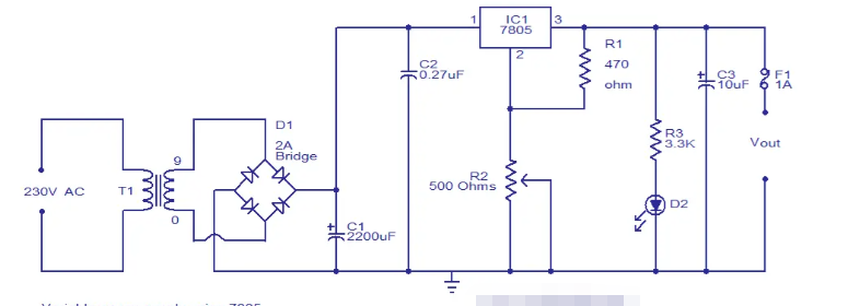
This circuit can be assembled on a vero board.
T1 can be a 230V primary, 9V/5A secondary step-down transformer.
The 7805 must be equipped with a heat sink.
F1 can be a 1A fuse.
7805 adjustable voltage regulator circuit diagram (II)
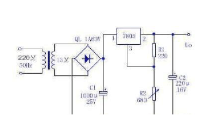
The 7800 series three-terminal voltage regulator integrated circuit is widely used in various electronic and electrical circuits as power supply voltage regulator. Its output voltage is fixed, but with a slight change in the peripheral circuit, it can become a good continuously adjustable voltage regulator, which is completely feasible for experimental maintenance.
Before making it, you need to know that the 7800 series three-terminal regulators are divided into three series according to the output current, namely the 78LO0 series with a maximum output current of 0.1A; the 78MO0 series with a maximum output current of 0.5A; and the 7800 series with a maximum output current of 1.5A. The input-output voltage difference of the three-terminal regulator must be greater than 2V. The maximum input voltage of 7805-7818 cannot exceed 35V, and the maximum input voltage of 7820-7824 cannot exceed 40V.
Here, 7805 is used to make a 5V~12V continuously adjustable DC regulated power supply. The values of R1 and R2 in the figure determine the adjustable range of the output voltage. According to the values shown in the figure, the output voltage can be continuously adjusted within the 5~12V regulated voltage range.
The maximum output voltage is limited by the maximum input voltage and the minimum input-output voltage difference of the three-terminal regulator. The maximum input voltage of 7805 is 35V, and the input-output voltage difference must be kept above 2V. Therefore, the DC input voltage of the regulator in this circuit is about 15V, and the maximum output voltage of this circuit is set to 12V.
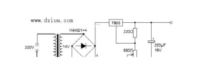
7805 adjustable voltage regulator circuit diagram (Part 3)
Usually when making some small things, it is inevitable to use a DC power supply between 5V and 12V, so it is necessary and practical to make a simple voltage-stabilized power supply by yourself. The circuit is very simple. Use the voltage-stabilizing effect of 7805 to make an adjustable power supply:
In the figure, R1 is 220Ω, and R2 is 680Ω sliding rheostat, which is mainly used to adjust the output voltage. The output voltage is UosUxx (1+R2/R1). This circuit can achieve continuous adjustable output voltage within the voltage regulation range of 5~12V.
The practice of this circuit proves that: (1) R1 is a fixed resistance value. By changing the resistance value of resistor R2, a continuously adjustable output voltage can be obtained. The output voltage Uo is approximately equal to Uxx (1+R2/R1). (2) The maximum output voltage is limited by the maximum input voltage and the minimum input-output voltage difference of the voltage regulator. The maximum input voltage of the fixed three-terminal integrated voltage regulator integrated circuit 7805 is 35V, and the input-output difference must be maintained above 2V. If the DC input voltage of the voltage regulator in this circuit is +14V, the maximum output of the circuit is +12V (you can directly use a 12V switching adapter to connect to pin 1 of 7805. At this time, the maximum DC of 10.6V can be obtained through experiments. I used R1=200 ohms and R2 is a 1k potentiometer).
- Transformerless Switch Mode Power Supply Circuit Diagram Explanation
- How to enhance power and signal integrity through low noise?
- What is a battery management system? Analysis of the uses of power management systems
- TPS274C65 helps reduce downtime and increase productivity in 24 VDC power distribution plants
- Energy-saving motorcycle rectifier regulator
- Step-down power supply for driving relays
- INA155/INA156 is used to form a single-supply high-side current monitor for detecting load current
- Visible laser digital control modulation driver
- Boost drive circuit composed of RT8450
- A simple positive and negative power supply circuit
- Voltage stabilization control circuit in power circuit
- Power circuit with smoothing filter capacitor
- Commonly used power circuits in printers
- 2-phase CPU power supply circuit using HIP6302 and HIP6602 chips
- Single LTC power circuit
- Common power circuits and applications 03
- Common power circuits and applications 01
- 5V, 7.5V, 48V power circuit
- ±5V, ±12V power circuit B
- Maintenance and experiment of multi-purpose power circuits


 京公网安备 11010802033920号