Analysis of transistor voltage-stabilized power supply circuit diagram
Source: InternetPublisher:fish001 Keywords: Regulated power supply circuit transistor power supply circuit diagram Updated: 2025/02/28
Transistor-based series regulator power supply circuit
The circuit shown in the figure below is a basic transistor based series regulator. Transistors Q1 (2N3054) and Q2 (2N3055) form a Darlington pair. Resistor R1 provides base current to Q1 and keeps Zener diode D2 in the active region. The overall working of the circuit can be demonstrated by explaining two scenarios.
When the input voltage (output of the rectifier section) increases, the output voltage of the regulator (Vout) also increases. The increase in Vout reduces the base emitter voltage of Q2 because the Zener diode D2 operates in the breakdown region and the voltage across it is constant. The reduction in VBE increases the collector emitter resistance of Q2, so the output voltage (Vout) decreases accordingly.
When the output load increases, the output voltage (Vout) decreases. The decrease in output voltage (Vout) causes the VBE of Q2 to decrease. This reduces the collector emitter resistance of Q2, so the output voltage increases accordingly.
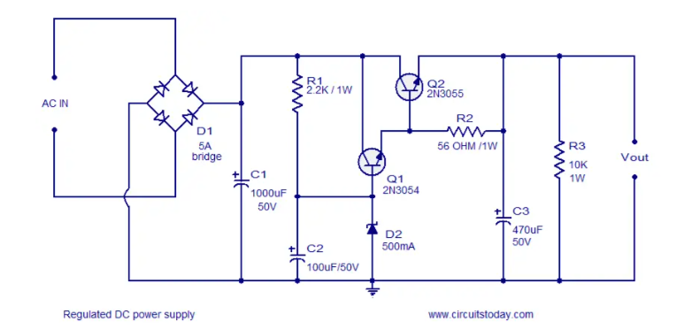
If you don't have a 5A bridge, make one using 6A6 diodes.
Transistor Q2 requires a heat sink.
An optional 5A fuse can be added in series with the output.
The breakdown voltage of the Zener diode D2 must be chosen based on the output voltage you require and according to the formula Vout = Vz – 0.7.
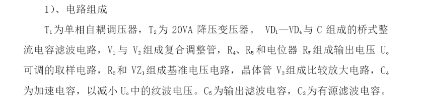
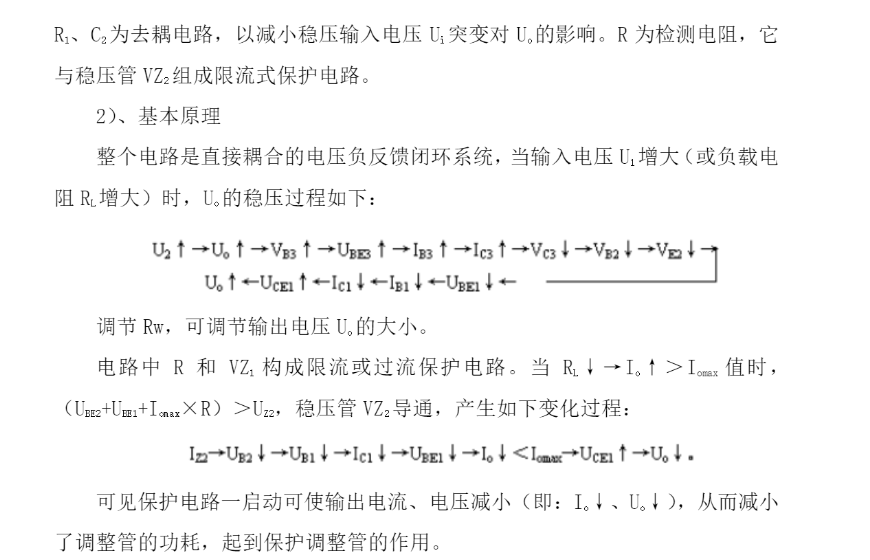
Experimental circuit of series voltage-stabilized power supply based on transistor
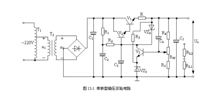
Compared with parallel type stabilized power supply, series type stabilized power supply has the advantages of good output voltage stability and adjustable output voltage, and is widely used, but its efficiency is relatively low, generally 50%-75%. A large amount of circuit consumption is in the adjustment, which makes the adjustment tube easy to heat up and damage. Therefore, in the experiment, especially when doing current limiting protection experiment, the action should be fast to avoid damaging the adjustment tube.
- Transformerless Switch Mode Power Supply Circuit Diagram Explanation
- A very convenient small power supply circuit to share
- How to Make a Soft Latch Circuit
- Step-down power supply for driving relays
- Transformerless AC-DC constant current LED driver circuit
- Dual forward converter schematic diagram
- A novel and practical DC low voltage stabilized power supply
- Power supply circuit that can reduce LM317 ripple
- Homemade low-power UPS
- LM317 regulated power supply
- Transistor Audio Mixer Circuit Diagram
- Capacitive feedback oscillator circuit
- 90MHz transistor resonant power amplifier circuit
- Touch switch power circuit
- Transistor controlled rectifier circuit d
- Paper tension control circuit
- Three-phase motor phase failure transistor protection circuit
- Alarm circuit for induction cooker
- Ground drain amplifier circuit connections
- One of the no-load automatic stop circuits of transistor type AC arc welding machine


 京公网安备 11010802033920号