How does a battery management system work and how to design a battery management system (BMS)?
Source: InternetPublisher:国民男神经 Keywords: Battery Management System BMS Updated: 2025/02/28
Overview
Battery-powered applications have become commonplace over the past decade, but such devices often require a certain level of protection to ensure safe use. Battery management systems (BMS) monitor batteries and possible fault conditions to prevent battery performance degradation, capacity loss, and even situations that could harm the user or the surrounding environment. The BMS is also responsible for providing accurate battery state of charge (SOC) and health status (SOH) estimates to ensure an informative and safe user experience throughout the battery's lifecycle. A properly designed BMS is not only critical for safety, but also a key link in improving customer satisfaction.
The complete structure of a BMS for medium and low voltage applications mainly consists of three ICs: analog front end (AFE), microcontroller (MCU) and fuel gauge (see Figure 1). The fuel gauge can be a stand-alone IC or embedded in the MCU. The MCU is the core component of the BMS, which obtains information from the AFE and fuel gauge and connects to the rest of the system.
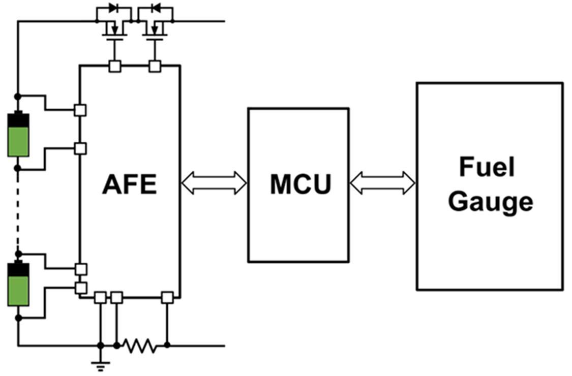
Figure 1: BMS structure
The AFE provides the MCU and fuel gauge with voltage, temperature, and current readings of the battery. Since the AFE is physically closer to the battery, it is recommended that the circuit breaker is also controlled by the AFE; in the event of a fault, the circuit breaker disconnects the battery from the rest of the system.
The fuel gauge IC takes readings from the AFE and then uses sophisticated battery modeling and advanced algorithms to estimate key parameters such as state of charge (SOC) and state of health (SOH). Similar to the AFE, some of the fuel gauge tasks can be included in the MCU code; however, using a dedicated fuel gauge IC (such as MPS' MPF4279x fuel gauge family) has additional advantages, as listed below:
Efficient Design: By using a dedicated IC to run complex power calculation algorithms, designers can use a lower specification MCU, thereby reducing overall cost and current consumption.
Improved Insight and Safety: Dedicated fuel gauges can measure the SOC and SOH of each series-connected cell in the battery stack, enabling higher measurement accuracy and providing aging detection over the battery lifecycle. Aging detection is important because battery impedance and capacity diverge over time, affecting run time and safety.
Faster time to market: Fuel gauge ICs are typically thoroughly tested for a variety of conditions and test cases. This reduces the time and cost of testing complex algorithms while accelerating time to market.
Improved state of charge (SOC) and state of health (SOH) accuracy
The primary goal of designing an accurate BMS is to achieve accurate calculations of the battery pack SOC (remaining run time/full range) and SOH (life and condition). BMS designers may think that the only way to achieve this is to use a very expensive AFE with accurate cell voltage measurement tolerance. In reality, the AFE is only one factor that affects the overall calculation accuracy. The most important factors are the fuel gauge cell model and the fuel gauge algorithm, followed by the AFE's ability to provide synchronized voltage-current readings for the cell resistance calculation.
The fuel gauge typically runs complex calculations using an internal algorithm that analyzes voltage, current, and temperature measurements in relation to a specific battery model stored in its memory before converting these measurements into SOC and SOH outputs. The battery model is generated by characterizing the battery at different temperatures, capacities, and load conditions, mathematically defining its open circuit voltage as well as resistance and capacitance components. Based on the battery model, the fuel calculation method is able to calculate the optimal SOC based on the changes in these parameters under different operating conditions. Therefore, if the battery model or algorithm of the fuel gauge is not accurate enough, no matter how accurate the AFE measurement is, the calculation result will be inaccurate. In other words, using a high-precision fuel gauge has the greatest
impact on the SOC accuracy of the BMS.
Voltage and current synchronous reading
Although most AFEs provide different ADCs for voltage and current, not all AFEs can provide actual simultaneous current and voltage measurements for each cell. The voltage-current simultaneous reading function allows the fuel gauge to accurately estimate the battery equivalent series resistance (ESR). Since ESR changes with different operating conditions and time, real-time ESR estimation can achieve more accurate SOC estimation.
Figure 2 shows that the SOC error of synchronous reading is significantly lower than that of asynchronous reading, especially after several discharge cycles. The following results were obtained using the MPF42791 with integrated ESR sensing and thermal modeling.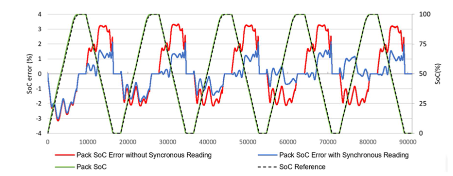
Figure 2: Comparison of SOC error between synchronous and asynchronous reading
AFE direct fault control
As mentioned earlier, the most important task of AFE in BMS is protection management. AFE can directly control the protection circuit to protect the system and battery when a fault is detected. Some systems implement fault control through MCU, but this design has a long response time and requires more resources from MCU, which increases the complexity of the firmware.
The advanced AFE detects fault conditions through its ADC readings and user configuration. It reacts to faults by turning on the protection MOSFET, ensuring true hardware protection. Moreover, the AFEs are fully tested, making it easy to ensure a robust safety system. In this way, the MCU can serve as a secondary protection mechanism to achieve a higher level of safety and robustness.
MPS' MP279x family integrates both forms of protection control. Designers can choose whether to control fault response and/or protection through the AFE or the MCU.
High-side battery protection and low-side battery protection
In BMS design, the placement of the battery protection circuit breaker is very important. These circuits are usually implemented with N-channel MOSFETs because they have lower internal resistance than P-channel MOSFETs. The circuit breaker can be placed on the high side (positive terminal of the battery) or the low side (negative terminal of the battery).
The high-side architecture ensures a good ground (GND) reference at all times, thus avoiding potential safety and communication failures in the event of a short circuit. In addition, a clean, stable GND connection helps reduce fluctuations in the reference signal, which is critical to the precise operation of the MCU.
However, when the N-channel MOSFET is placed at the positive terminal of the battery, its gate drive voltage needs to be higher than the battery pack voltage, which is a design challenge. Integrating a dedicated charge pump into the AFE is a common high-side architecture, but this increases the overall cost and IC current consumption.
The low-side configuration does not require a charge pump because the protection MOSFET is located at the negative terminal of the battery. However, it is more difficult to achieve effective communication in the low-side configuration because there is no GND reference when the protection is turned on.
The MP279x family uses a high-side architecture to provide powerful protection features while minimizing BOM. In addition, the high-precision charge pump control also supports the soft turn-on function of the N-channel MOSFET, which does not require any additional pre-charge circuit, which further reduces the BOM size and cost to a very low level. Soft turn-on is achieved by slowly increasing the gate voltage of the protection FET, which allows a small current to flow through the protection device to pre-charge the load (see Figure 3). A safe transition can be ensured by configuring several parameters, such as the maximum allowed current, or the time until the protection FET is turned off without triggering a fault.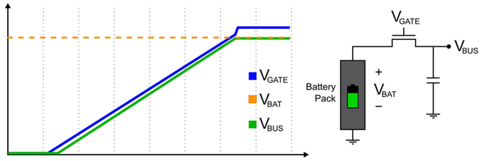
Figure 3: MP279x series soft turn-on solution
Cell balancing function to extend battery life
Battery packs that power larger systems, such as e-bikes or energy storage devices, typically consist of multiple cells connected in series and parallel. Each cell should theoretically be identical, but due to manufacturing tolerances and chemical differences, each cell typically behaves slightly differently. Over time, under different operating conditions and aging, these differences become more significant, which can severely impact battery performance by limiting its usable capacity or potentially damaging the cell. To avoid these dangers, it is critical to regularly equalize the voltages of the series-connected cells through cell balancing.
Passive balancing is the most common method for balancing battery voltages. It requires discharging the battery with the larger charge until all cells have an equal charge. The passive cell balancing function in the MP279x series AFE can be completed externally or internally. External balancing allows for larger balancing currents, but also increases the BOM (see Figure 4).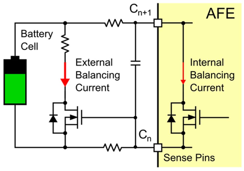
Figure 4: External battery balancing
Internal balancing does not increase the BOM, but it usually limits the balancing current to a lower value due to heat dissipation issues (see Figure 5).
When choosing between internal balancing and external balancing, the external hardware cost and the target balancing current need to be considered.
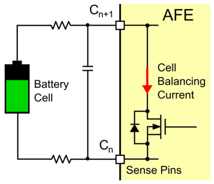
Figure 5: Internal cell balancing
Another important factor in cell balancing is the physical connection. For example, the MP279x AFE family uses the same pins for voltage sampling and balancing. This greatly reduces the IC size, but also means that consecutive cells cannot be balanced at the same time, thus increasing the time required to complete cell balancing. Using dedicated balancing pins can save balancing time, but it will significantly increase the IC size and overall cost.
AFE Safety Features
As mentioned above, the AFE used to control system protection and fault response is extremely important in BMS design. The AFE must be able to detect the adverse condition before turning the protection FET on or off.
Faults at the cell and pack levels, such as overvoltage (OV), undervoltage (UV), overcurrent (OC), short circuit (SC), overtemperature (OT) and undertemperature (UT) should be monitored. AFE can also provide other beneficial protections and functions for some applications. For example, the self-test function allows the IC to detect whether its internal ADC fails, thereby preventing the system from making erroneous measurements; the enhanced watchdog timer can also ensure robustness and safety when the main MCU is not responding.
The MP279x family of devices offers the above fault protection with high configurability, allowing the user to define different thresholds, deglitch times, and hysteresis for each fault. These devices also compare the fault conditions of SC and OC through two different comparators to minimize the response time. The devices also offer fault auto-recovery configuration, which means they can automatically recover from most faults without the MCU
taking any action.
Conclusion
The BMS monitors the battery pack to protect the cells and the rest of the system. A poorly designed BMS not only reduces the safety of the system, but also leads to inaccurate battery SOC management. This inaccuracy has a huge impact on the final quality of the product, with a high probability of causing potentially dangerous failures or producing malfunctions that result in a poor user experience. To mitigate these issues, this article explains the factors and goals that designers should focus on in BMS design.
- Pulse interference on the car power line, the shortcomings of the PMOS anti-reverse protection circuit
- Smart Farm Design Solution Based on LoRa
- Telephone line protection alarm circuit
- Homemade disinfectant circuit
- Vehicle electronic fuel gauge circuit
- Catillac luggage compartment opening circuit diagram
- Electric massager circuit
- Box type electronic mousetrap circuit
- Chinese learning machine disk drive interface card circuit diagram circuit
- Human body approaching safety protection warning circuit


 京公网安备 11010802033920号