How do I choose the gain of an operational amplifier?
Source: InternetPublisher:偷熊计划 Keywords: Operational amplifier gain Updated: 2025/02/25
Before choosing, determine the bandwidth of the signal that your system will pass through the amplifier. Remember to avoid using analog devices that are too fast for your application, and try to choose an amplifier with a closed-loop bandwidth slightly higher than the maximum frequency of your signal.
In the lab, you might find that when you put an input sine wave signal at the maximum frequency of your application into your system, the op amp’s output signal doesn’t cross the full-scale analog range you’d expect. The signal gain is much lower than expected. The op amp’s slew rate rating is higher than needed. And, it’s not driving the op amp’s output to the supply rails. What’s going wrong?
No more double-checking your resistor values! When designing an op amp in a gain block, there are a few things you need to know when selecting a candidate op amp for the job. For example, what is the maximum signal bandwidth (SBW) of the op amp? What is the op amp closed-loop noise gain (NG), and what is the gain-bandwidth product (GBWP) of the op amp under consideration? Also, how much gain error is allowed? The closed-loop noise gain is simply the op amp gain, like a small voltage source in series with the op amp's noninverting input.
Let's illustrate this with an example. For example, starting with a 1 MHz signal bandwidth (SBW), the amplifier circuit shown in Figure 1 has a noise gain (NG = 1 +9R/R) of 10V/V. Figure 1 also shows the open-loop frequency response of an amplifier with just enough bandwidth for this circuit; or whatever you think is appropriate. The amplifier GBWP is 16
MHz.
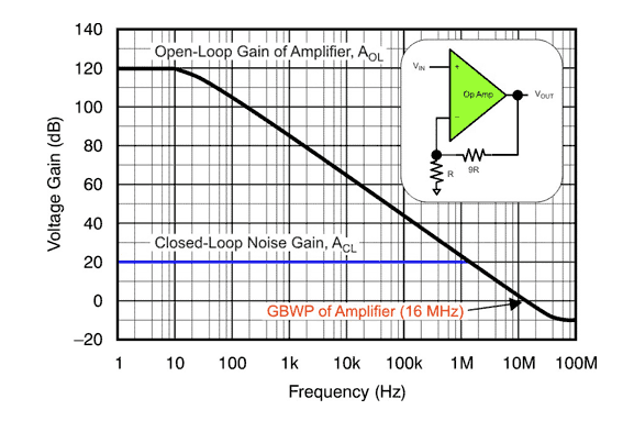
Figure 1 The open-loop and closed-loop gains of this voltage feedback amplifier have a gain-bandwidth product of 16 MHz and a circuit noise gain of 10 V/V.
As shown in Figure 1, an op amp like this can support a gain of 10 V/V (20 dB) at 1 MHz, but we need to investigate further.
The gain of the open-loop gain curve is:
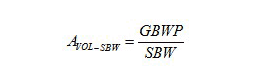
In our example, the open-loop gain of the amplifier at 1 MHz (AVOL-SBW) is equal to 16 V/V. However, that is nothing to complain about. The closed-loop gain error of this circuit is equal to
NG / (AOL - SBW + NG). In our example, the 1 MHz closed-loop gain error equals 0.385, which is a gain error of 38.5%!
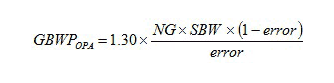
For this circuit, if you want to tolerate a 0.05 gain error in the amplifier, and you know that the amplifier's GBWP will vary by 30% maximum across product and temperature, you need a
The guiding formula for the product selection section is as follows:
- TL783 parameters/pin configuration and functions, tl783 parameter circuit diagram
- Summary of I2C basics: How does I2C communication actually work?
- LM337 pin diagram and parameters, LM337 application circuit diagram
- What is the function of a voltage regulator in a circuit? How to connect a voltage regulator?
- Signal diode arrays/configurations, freewheeling diode operation
- How does a series arrangement of Zener diodes affect the electrical behavior?
- How to identify common mode interference? Methods to eliminate common mode interference
- Analysis of the basic principle of measuring resistance by bridge method
- What are the parts of the fpga design process
- Datasheet/Pinout/Technical Specifications of LMC555
- AC voltage current
- Practical amplifier circuit consisting of operational amplifier LM386 e
- Output voltage expansion circuit a
- Operational amplifier stabilized power supply circuit three
- One of the thermostatic control circuits using operational amplifiersb
- One of the thermostatic control circuits using operational amplifiers a
- Optoelectronic relay circuit using operational amplifier
- Simple sinusoidal oscillator circuit using op amp
- Speed control system block diagram circuit using operational amplifier
- Tuned notch filter using an operational amplifier


 京公网安备 11010802033920号