What is a photocoupler and how to select and use one?
Source: InternetPublisher:宋元浩 Keywords: Coupler Optocoupler Updated: 2025/02/11
Photocouplers, which connect circuits using optical signals as a medium, are an element that is active in fields that require high precision, such as acoustics, medicine, and industry, due to their high versatility and reliability, including durability and insulation.
However, when and under what circumstances does the photocoupler work, and what is the principle behind it? Or when you actually use a photocoupler in your own electronic work, you may not know how to choose and use it. Since people often confuse optocouplers with "phototransistors" and "photodiodes", this article will introduce what a photocoupler is.
1. What is a photocoupler?
Optocoupler is an electronic component. Its etymology is the English word optical.
Coupler, meaning "coupled with light". Sometimes also called optocoupler, opto-isolator, opto-insulation, etc. It consists of a light-emitting element and a light-receiving element, connecting the input side circuit and the output side circuit through an optical signal. There is no electrical connection between these circuits, in other words, in an insulating state. Therefore, the circuit connection between the input and output is separated, and only the signal is transmitted. It is possible to safely connect circuits with significantly different input and output voltage levels, and high-voltage insulation materials are used between the input and output.
Furthermore, by passing or blocking this light signal, it acts as a switch. The detailed principle and mechanism will be explained later, but the light-emitting element of the photocoupler is an LED (light-emitting diode).
From the 1960s to the 1970s, when LED was invented and its technology progressed significantly, optoelectronics became a boom. Various optical devices were invented at that time, and optocoupler was one of them. Subsequently, optoelectronics quickly penetrated into our lives.
①Principle/Mechanism
The principle of the photocoupler is that the light-emitting element converts the input electrical signal into light, and the light-receiving element transmits the light back to the electrical signal to the output side circuit. The light-emitting element and the light-receiving element are inside the device that blocks external light, and the two are opposite to each other to transmit light.
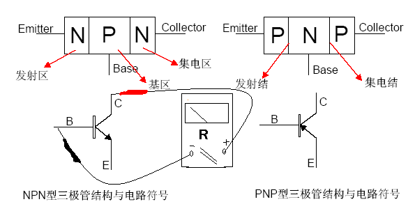
The semiconductor used for light-emitting elements is LED (light-emitting diode). On the other hand, there are many types of semiconductors used in light-receiving elements, depending on the usage environment, external dimensions, price, etc., but generally speaking, the most commonly used is the phototransistor.
When not working, the phototransistor has almost no current transmission like ordinary semiconductors. When light is incident there, the phototransistor generates photoelectromotive force on the surface where the p-type semiconductor and n-type semiconductor are combined, the holes in the n-type semiconductor flow into the p-region, and the free electrons in the p-region flow into the n-region, and current will flow.
Phototransistors are not as responsive as photodiodes, but they also have the effect of amplifying their output by hundreds to 1000 times the input signal (due to internal electric fields). Therefore, they are sensitive enough to capture even weak signals, which is an advantage.
In fact, the "photointerrupter" we see is an electronic device with the same principle and mechanism.
However, photointerrupters are often used as sensors and function by passing a light-blocking object between a light-emitting element and a light-receiving element. For example, it can be used to detect coins and banknotes in vending machines and ATMs.
② Features
Since photocouplers transmit signals using light, the insulation between the input side and the output side is a major feature. High insulation is not easily affected by noise, and it can also prevent unexpected current from flowing between adjacent circuits, which is extremely effective in terms of safety. In addition, the structure itself is relatively simple and reasonable.
The long history and rich product lineup of each manufacturer are also the unique advantages of photocouplers. Since there is no physical contact, there is little wear between parts and the life is relatively long. On the other hand, there is also the characteristic that the luminous efficiency is easy to fluctuate because LEDs will slowly deteriorate over time and temperature changes.
Especially when the transparent plastic of the internal components becomes cloudy over time, it does not shine well. However, in any case, the life is too long compared to the contact type contacts of mechanical contacts.
Phototransistors are generally slower than photodiodes, so they are not used for high-speed communications. However, this is not a disadvantage, as some components have amplifier circuits on the output side to increase speed. In fact, not all electronic circuits need to increase speed.
③Usage
Photocouplers are mainly used for switching operations. The circuit will be energized by turning on the switch, but from the perspective of the above characteristics, especially insulation and long life, it is very suitable for scenes requiring high reliability. For example, medical electronic equipment and audio equipment/communication equipment where noise is the enemy.
It is also used in motor drive systems. The reason for the motor is that the speed is controlled by the inverter when it is driven, but noise is generated due to the high output. This noise not only causes malfunctions in the motor itself, but also flows through the "ground" to affect peripheral devices. In particular, devices with long wiring are prone to picking up this high output noise, so if it occurs in a factory, it will cause great losses and sometimes serious accidents. By using a high-insulation photocoupler for switching, the impact on other circuits and equipment can be minimized.
2. How to select and use optocouplers
How to use the appropriate optocoupler for product design? Below, the MCU development engineer of Inruien will explain how to select and use optocouplers.
① Normally open and normally closed
There are two types of photocouplers: a type in which the switch is off (open) when no voltage is applied and on (closed) when voltage is applied, and a type in which the switch is on when no voltage is applied and off when voltage is applied.
The former is called normally open, and the latter is called normally closed. How to choose depends on which one your circuit requires.
② Check the output current and applied voltage
The photocoupler has the property of amplifying the signal, but it does not always pass the voltage and current as you wish. Of course, it is rated, but it needs to apply a voltage from the input side according to the required output current.
If we look at the product datasheet, we can see a graph with the vertical axis being the output current (collector current) and the horizontal axis being the input voltage (collector-emitter voltage). The collector current varies depending on the LED light intensity, so apply a voltage based on the desired output current.
However, you might think that the output current calculated here is unexpectedly small. This is because the current value that can be reliably output after taking into account the degradation of the LED over time is less than the maximum rating.
On the contrary, there are also cases where the output current is not large. Therefore, when choosing a photocoupler, you must carefully check "how much current is output" and choose a product that matches it.
③Maximum current
The maximum on-current is the maximum current the optocoupler can handle when it is on. Again, we need to make sure we know how much output the project requires and what the input voltage is before purchasing. Make sure the maximum value and current used are not a limitation, but have some margin.
④ Correctly set the photocoupler
After choosing the right optocoupler, let's use it in a real project. The installation itself is easy, just connect the terminals connected to each input side circuit and output side circuit. However, you need to be careful not to get the direction of the input side and the output side wrong. So, you have to check the symbols in the datasheet, so as not to find out that the optocoupler pins are wrong after drawing the PCB board.
- What is a photocoupler and how to select and use one?
- RC filter explained in detail
- How to calculate the value of capacitors in parallel?
- Simple Wired Spy Bug Circuit Built Based on IC741
- Working principle/characteristics/application fields/equivalent circuit of unijunction transistor
- Working principle/advantages/disadvantages/size of optical fiber
- How to Build a Simple Temperature Indicator Circuit Using NTC and PTC Thermistors
- How to build a drag racing timer circuit using a 7-segment display and discrete components
- Ceramic filter structure/working principle/characteristics/application
- Star finder battery indicator circuit
- How does an optocoupler amplifier circuit work?
- Photoelectric isolation circuit design plan
- Photoelectric drive circuit
- Optocoupler controlled oscillator
- Interface circuit for automatic counting using electronic counter b
- Interface circuit between power supply coupler and relay
- Power outage alarm circuit three
- Optocoupler MOC304 dimming control circuit diagram
- Series photocoupler control thyristor switching circuit
- Zero detection circuit using 2 photocouplers


 京公网安备 11010802033920号