Why use PWM? What are its advantages?
Source: InternetPublisher:赔钱虎 Keywords: PWM digital system pulse signal Updated: 2025/01/03
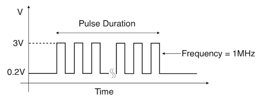
Let's first understand what a pulse is? This is one of the most important concepts in basic electronics. In a digital system, there are two possible output states: a digital high or "1" and a digital low or "0". A pulse is a continuous signal that contains a sequence of these 1s and 0s. The image below shows a digital pulse with a logic 1 or high logic of 3V and a logic 0 or low logic of 0.2V. This alternate logic state repeats over the entire period of time, thus making it a digital pulse signal.
What is PWM or Pulse Width Modulation:
The term modulation refers to the modulation or manipulation of one signal with another to obtain a signal with higher strength. This is common in transmission systems to achieve the transmission of audio signals.
Likewise, when we say PWM, it means modulating the pulses of a digital signal using another signal (most commonly an analog signal).
The resulting signal of this modulation will have a modified width in its logic state, as shown in the figure above. If you look closely at the figure above, you can see that the width of the high state is different from each other logic 1. This essentially means that each logic high level lasts for a different amount of time, so a modified width pulse signal can be seen above.
Why use PWM:
PWM signals play an important role in power supply PCBs, driver circuits, etc. When a device is driven using a PWM signal instead of a steady DC signal. Due to the different nature of the ON and OFF states, using PWM we will be able to control the amount of time that current actually flows through the device.
When the pulse is in the ON state, current is delivered to the device, and when the signal is in the OFF state, no current flows. When the pulse frequency is high enough, the power supply to the device is not interrupted at all, allowing it to operate normally while consuming less current. This is explained further below.
PWM Duty Cycle
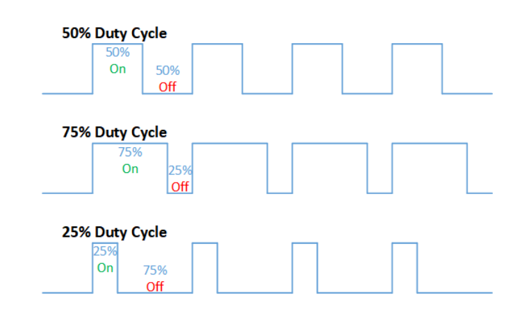
The duty cycle is defined as the percentage of time that the high state is shown per cycle. Using the duty cycle, we can deduce the average current from the PWM signal, and the output can be obtained by taking the average of the on-time and the off-time.
Assume the device is driven by a PWM signal with a 50% duty cycle where the timing of the high and low states are equal. Now we can say that the current consumed by the device will be 1/2 of the current consumed when driven by a DC signal.
Similarly, a 25% duty cycle PWM signal provides 1/4 and 75% duty cycle PWM provides 3/4 of the current to the device compared to a normal DC signal.
Advantages of Pulse Width Modulation
The PWM signal will save power consumption by delivering an average current to the target device.
An efficient way to control motor speed and LED brightness.
- Signal diode arrays/configurations, freewheeling diode operation
- An article explains the working principle of the Wheatstone bridge
- FPGA Features and Architecture
- What are the parts of the fpga design process
- How to calculate the value of capacitors in parallel?
- Basic characteristics/working principles and application circuits of tunnel diodes
- How to Build a Simple Temperature Indicator Circuit Using NTC and PTC Thermistors
- Make a flameless electronic candle using simple electronics and LEDs
- How to build a triangle wave generator using an op amp and discrete components
- How to install the accelerometer
- Classification analysis of PWM control
- Pulse signal generation and display circuit b
- Counter composed of 4 T flip-flops
- Broadband square wave oscillator
- Keying pulse signal generation circuit
- Typical computer motherboard CPU power supply circuit
- Interface circuit c for automatic counting with electronic counter
- Precise high current drive circuit
- Digital PWM connection diagram composed of ZPS-101
- Three-terminal PWM switching power supply-PWR-TOP200 series and applications 02


 京公网安备 11010802033920号