How to build a triangle wave generator using an op amp and discrete components
Source: InternetPublisher:newrudeman Keywords: Operational amplifier discrete components triangle wave generator Updated: 2024/12/24
Function generator or waveform generator is a component of electronics which is used to generate various waveforms like sine wave, square wave, sawtooth wave etc. We have already designed sine wave generator circuit, square wave generator circuit and sawtooth wave generator circuit. Now in this tutorial, we will show you how to design a triangle waveform generator circuit using an operational amplifier and some basic components.
A triangle wave consists of one constant rising slope and one constant falling slope, and the wave resembles a poorly drawn mountain range.
Triangle wave generators are used in various things such as transistor curve tracers, PWM controllers, Class D amplifiers, and tone generators.
Parts Required
1x LM358 or similar op amp
3x 1K resistors
1x 10K resistor
1x 100K Resistor
1x 1nF Ceramic Capacitor
1x 1uF electrolytic capacitor
Operational Amplifier LM358
An operational amplifier is also called a voltage comparator. When the voltage at the non-inverting input (+) is higher than the voltage at the inverting input (-), the output of the comparator is high. If the inverting input (-) voltage is higher than the non-inverting terminal (+), the output is low. Learn more about the working of an operational amplifier here.
LM358 is a dual low noise operational amplifier with two independent voltage comparators inside. It is a general purpose operational amplifier that can be configured in various modes such as comparator, adder, integrator, amplifier, differentiator, inverting mode, non-inverting mode, etc. To learn more about LM358, go through LM358 Various Circuits as Amplifier and Comparator
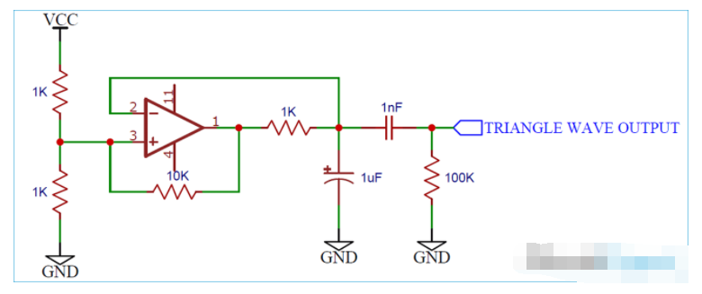
Circuit Schematic
The schematic diagram of the operational amplifier triangle wave generator is as follows:
Working Principle of Triangle Wave Generator
This circuit is a simple example of a relaxation oscillator using a single op amp as a comparator.
Initially, let's assume the capacitor is discharged. This puts the inverting input at a voltage lower than the non-inverting input, half the voltage of the resistor divider supply.
The output goes high until the capacitor voltage exceeds half the supply voltage, at which point the inverting input has a greater voltage than the non-inverting input. The output then goes low, discharging the capacitor. At the same time, the 10K resistor acts as hysteresis - when the output goes low, the bottom leg of the voltage divider now has a 1K and a 10K in parallel, reducing the overall resistance and lowering the reference voltage.
The value of the hysteresis resistor and the resistor divider can be changed to increase or decrease the frequency.
The output of the op amp is then AC coupled to produce a signal with equal positive and negative swings. This signal can be easily amplified.
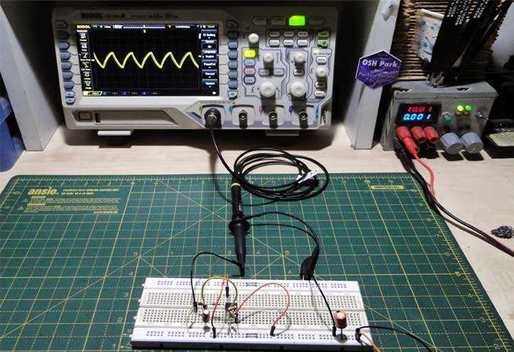
So, this is how you build a simple triangle wave generator using a single op amp and a handful of discrete components.
- Signal diode arrays/configurations, freewheeling diode operation
- Symbol/working principle/type/characteristics/application scenarios of depletion-mode MOSFET
- Capacitance detection circuit configuration, how to deal with low frequency and high frequency noise?
- Advantages and disadvantages of organic semiconductors, the conductive mechanism of organic semiconductors
- How do you calculate the value of capacitors in series? Why use capacitors in series?
- Working principle and truth table of JK flip-flop
- What is power factor and three ways to improve it
- How to Build a Simple Temperature Indicator Circuit Using NTC and PTC Thermistors
- How to build a drag racing timer circuit using a 7-segment display and discrete components
- Digital number selection machine
- Resistor-Voltage Conversion Circuit
- Low output impedance operational amplifier circuit
- Zero-crossing signal detection circuit
- Discrete component headphone amplifier circuit diagram
- Discrete component amplification circuit diagram
- Optocouplers and discrete Schmitt triggers used to drive 54/74 TIL circuits
- Triangular wave generator circuit diagram that can accurately adjust the amplitude
- Precision clamped ultra-low frequency triangle wave generator circuit diagram
- 90-900HZ sine wave, square wave, triangle wave generator circuit diagram
- Discrete component touch switch circuit diagram


 京公网安备 11010802033920号