How to Build a Touch-Based Color-Changing Plant Using Arduino
Source: InternetPublisher:jikai233 Keywords: Touch RGB touch sensor Arduino Updated: 2024/12/19
In this article, we will learn how to build a touch based color changing plant using Arduino. When you touch the plant, the color of the plant vase will automatically change. This is a nice interior decoration project and also a small hobby project for beginners to build and learn something fun.
Now, when we say touch based plants, a common question may arise that how can the electronic circuit detect the touch of a human through plants. Touch sensing devices are everywhere these days. We can see touch screens in smartphones and different types of electrical appliances. A touch sensor is simply a switch, and when someone touches the touch sensor, the sensor turns off the electronic circuit and allows the flow of electricity.
Touch sensor type
From mobile phones to smart vending machines, we can find touch sensors in all modern devices today. There are two main types of touch sensors, namely, resistive touch and capacitive touch. The name of the type itself indicates the mode of operation and working principle.
Resistive touch sensor: As the name implies, the working principle of resistive touch sensor is based on the resistance of the conductor. When the human body touches it, the resistivity of the conductor will change, and the voltage will also change. This voltage change will be detected by the circuit, and something will happen.
Capacitive Touch Sensor: This is the most commonly used type of touch sensor. This is simply because we can perform more than one touch at a time. Capacitive touch sensors work on the basis of the change in capacitance i.e. when we touch the sensor, the capacitance of the circuit changes and this will be detected as a touch. Now let us discuss our circuit in detail.
How to detect touch on plants?
The circuit of our plant is also based on a capacitive touch sensor. That is, we attach a wire to our plant so that it acts like an electrode, and then when we touch the plant, the capacitance changes due to the presence of our body, which will be detected by our circuit. Speaking of the circuit, we need a microcontroller to detect the change in capacitance and control the whole system. In our case, the microcontroller is an Arduino.

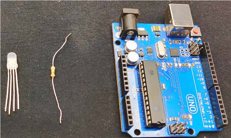
Materials Needed to Make Our Color Changing Plant Vase
Arduino
Common cathode RGB LED
1M Ohm resistor (brown, black, green)
Connection line
Plants with bases
Ordinary PCB
Arduino Plant Circuit Diagram
The complete circuit diagram used in this project is shown below. This circuit was created using Easy EDA and as you can see, it is a very simple circuit.
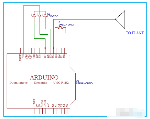
First, connect a megohm resistor between Arduino pin 2 and pin 4. Then connect a long wire (copper) to pin 4. This wire acts as an electrode or touch lead, then connect the RGB LED common ground to ground, red to green to D5 and D6 of Arduino, blue to D7, and finally connect the wires to the plant body, that's it. My hardware setup after the connections looks like this.
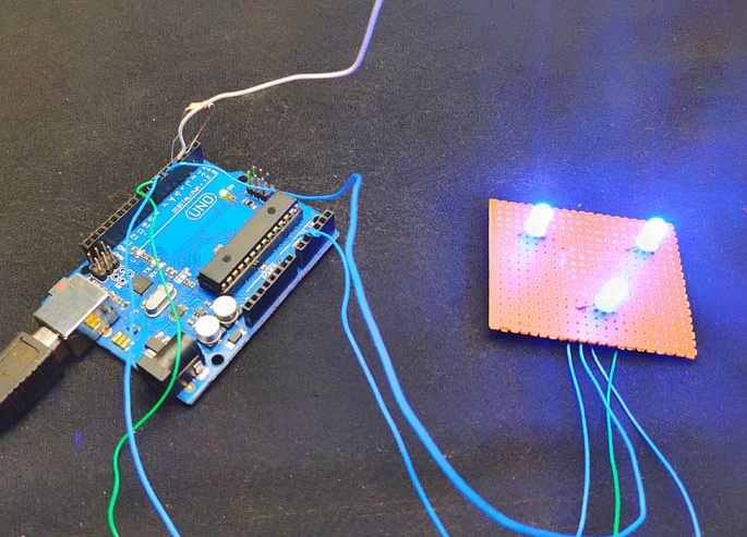
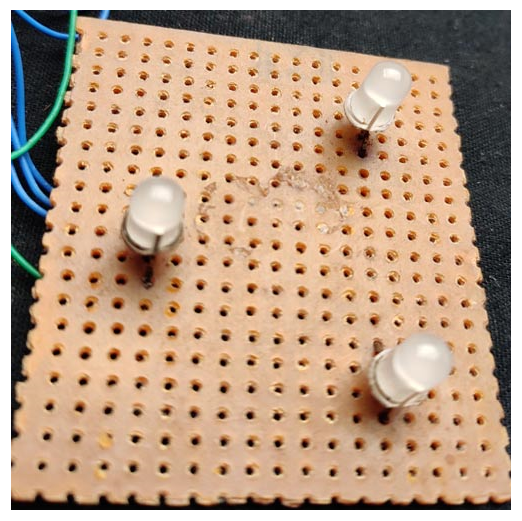
I have connected the RGB LED to a regular perfboard (as shown in the picture below) and finally placed the base (glass) above the PCB. That's it.
Arduino Program to Detect Plant Touch and Change LED Color
The complete program used in this project can be found at the bottom of this page. To detect the capacitance of the plant, we need to use the Capacitive Sensor Library. You can download the Arduino Capacitive Sensor Library from the following link.
Download the Arduino Capacitive Touch Sensor Library
After downloading the library and adding it to your Arduino IDE, include the library to your code. This library helps in reading the capacitance of the Arduino pins.
#include <capacitivesensor.h>
We have connected the resistor between pins 2 and 4, so we need to measure the capacitance in pin 4, for this, define the pins.
CapacitiveSensor cs_2_4 = CapacitiveSensor(2,4);
A capacitive sensor toggles a microcontroller pin, i.e. it sends the pin to a new state and then waits for the receiving pin to change to the same state as the sending pin. In the setup section, I defined different pins for the LED and sensor leads.
  pinMode(4, INPUT);
  pinMode(5, OUTPUT);
  pinMode(6, OUTPUT);
  pinMode(7, OUTPUT);
In the loop section with the help of digital read we can read the state of pin 4 and store the value in variable “r”.
r = digitalRead(4);
  if (r == HIGH && p == LOW && millis() -
Every time a touch is detected it increases the count and I gave different conditions to light up in different colors based on the number that was increased.
Once the code is ready, just upload it to your Arduino board and place the LEDs under your vase. Here, I am using a glass vase and my setup looks like this once everything is ready.
#include <capacitiveSensor.h> capacitiveSensor
cs_2_4 = capacitiveSensor(2,4); // there is a 1M resistor between pins 2 and 4, pin 4 is the sensor pin, add a wire and
int cnt = 0;
int = 2;
int = 4;
int state = HIGH;
int r;
int p = LOW;
time = 0;
time debounce = 200;
void setup()
{
pinMode(4, INPUT);
/* LED output */
pinMode(5, OUTPUT);
pinMode(6, OUTPUT);
pinMode(7, OUTPUT);
}
void loop()
{
r = digitalRead(4);
if (r == HIGH && p == LOW && millis() - time > debounce) {
cnt++;
if (state == HIGH)
state = LOW;
else
time = millis();
}
if (cnt == 1) {
digitalWrite(5, HIGH);
digitalWrite(6, LOW);
digitalWrite(7, LOW);
}
if (cnt == 2) {
digitalWrite(5, LOW);
digitalWrite(6, HIGH);
digitalWrite(7, LOW);
}
if(cnt == 3) {
digitalWrite(5, LOW);
digitalWrite(6, LOW);digitalWrite
(7, HIGH);
}
if(cnt > 3) {
cnt = 1;
}
p = r;
}
- Tutorial on making your own remote-controlled robotic arm
- Peripheral circuit of automotive motor controller power supply chip
- A small improvement on the ordinary refrigerator motor starting circuit
- A small improvement to the temperature and water level indicator alarm
- Working principle of one Xipu STR soft starter controlling two motors
- Design and production of radio remote control fan stepless speed regulator
- Design and analysis of a four-bit remote control component capable of remote reset
- Simple three-phase motor phase loss protection circuit
- Electric vehicle battery charging protection circuit
- A novel and practical power line anti-theft and cutting alarm circuit
- Homemade disinfectant circuit
- Egg heating control circuit
- Micro remote control receiving and control circuit
- Schematic diagram of motor PLC control circuit
- Digital current loop control circuit
- Detection and control circuit of electromagnetic stove
- Photoelectric detection output control circuit
- Intelligent iron control circuit
- Typical electronic volume control circuit
- 35W half-wave resistor-capacitor phase-shift trigger actuation control circuit


 京公网安备 11010802033920号