7 Watt Class A Audio Amplifier
Source: InternetPublisher:IxGF2I6 Keywords: Audio amplifier Updated: 2026/03/17
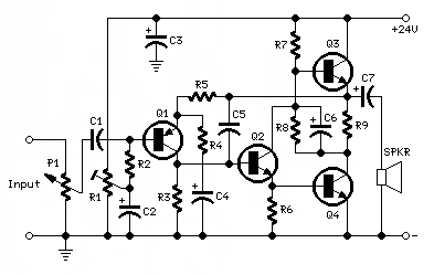
Circuit diagram:
Component:
P1_____________50K Logarithmic potentiometer (or 47K)
(For three-dimensional double concentric shaft double connection)
R1____________100K 1/2W Fine-tuning Ceramic Potentiometer
R2____________100K 1/4W resistor
R3______________8K2 1/4W resistor
R4, R8_________100R 1/4W resistors
R5______________2K7 1/4W resistor
R6______________1K 1/4W resistor
R7____________680R 1/4W resistor
R9______________1R 1/2W resistor
C1____________470nF 63V Polyester Capacitor
C2_____________47µF 25V electrolytic capacitor
C3, C6_________470µF 25V electrolytic capacitors
C4____________220µF 25V electrolytic capacitor
C5_____________47pF 63V Polystyrene or ceramic capacitor
C7___________1000µF 25V electrolytic capacitor
Q1___________BC560C 45V 100mA Low-noise, high-gain PNP transistor
Q2___________BC337 45V 800mA NPN transistor
Q3___________BD437 45V 4A NPN transistor
Q4___________BD675A 45V 4A NPN Darlington transistor
SPKR___________One or more speakers connected in series or parallel
Total impedance: 8 ohms
Minimum power handling: 10W
Comment:
More than a decade after its launch on this website and with increasing success, the 3-5W Class A audio amplifier has undergone some minor modifications (adding R1, Q2, and R6 and replacing Q4 with a Darlington transistor) that have resulted in significant improvements.
In fact, the open-loop gain is increased, distortion is significantly reduced across all power levels (e.g., up to 30 times less at 500mW), current consumption is reduced to less than 500mA, maximum output power is increased to 7.2W RMS at an 8-ohm load, and input sensitivity is fixed at approximately 250mV RMS. This allows CD players or tuners to be directly connected to the amplifier input without the need for a preamplifier.
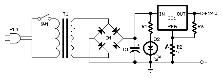
The reduced current consumption allows for the use of an ultra-simple yet efficient regulated power supply, employing the common LM317 IC, capable of driving two amplifiers (with appropriately sized heatsinks).
The amplifier power supply voltage must be precisely set to 24V using the trimmer R2 (see the power supply circuit diagram below).
In the amplifier, a trimmer R1 was added to ensure the maximum output power (7.2W RMS) possible. With this component, the voltage at the positive terminal of C6 must be precisely set to half of the supply voltage, i.e., 12V (when P1 is rotated completely counterclockwise).
Power supply circuit diagram:
Power supply components:
R1_______________2K7 1/2W resistor
R2_______________5K 1/2W Fine-tuning Ceramic Potentiometer
R3_____________220R 1/4W resistor
C1____________4700µF 35V or 50V electrolytic capacitor
D1_____ Diode bridge, 100 to 400V, 2 to 4A
D2______________LED Any type and color
IC1___________LM317 3-terminal adjustable voltage regulator 1.5A
SW1_____________SPST Power Switch
T1______________230V primary, 24V secondary,
30-32VA or 1.25 to 1.33A, power transformer
PL1_____________ Male power plug with cable
Comment:
The regulated power supply circuit is simple and straightforward. The recommended component values are applicable to the stereo version of this design.
Note:
- After connecting the two amplifiers to the regulated power supply, adjust the trimmer R1 to obtain an accurate 24V at the output pin of IC1.
- Adjust R1 in each amplifier to obtain an accurate 12V between the positive terminal of C6 and the negative ground.
- The total current consumption of each amplifier is approximately 450-500mA, which should not require adjustment.
- Each output transistor (Q3 and Q4) must be mounted on a heatsink with a minimum size of 120x50x25mm.
Technical data:
- Output power: 7.2 watts RMS (1kHz sine wave) under 8 ohm load
- Input sensitivity: 270mV RMS full output
- Frequency response @ 1W RMS: Flat from 50Hz to 20kHz; -2dB at 20Hz
- Total Harmonic Distortion @ 1kHz and 10kHz: 500mW 0.01% 1W 0.02% 2W 0.035% 3W 0.08% 5W 0.12% 7W 0.15%
- Unconditional stability under capacitive load
- Gain Cloning Power Amplifier LM3886
- 20-watt stereo amplifier using TDA2005
- TDA2822 Low Power Stereo Amplifier
- High-fidelity headphone amplifier
- TDA7294 Audio Amplifier
- 5 Watt Class A Audio Amplifier
- LM386 Bass Boost Circuit
- 5~200MHz, 75Ω impedance low frequency amplifier circuit composed of RF2360
- 20W single-ended pure class A amplifier
- LM1876 single power supply audio power amplifier circuit
- Low power audio amplifier MC34119-04
- Practical voice-controlled music lantern (1)
- 8W audio amplifier integrated circuit
- Output uses DC coupled 15 to 60W audio amplifier circuit
- 12W low noise audio amplifier circuit with boost transistor
- TDA2003 10W car radio audio amplifier
- Audio amplifier circuit using high gain field effect transistors
- 35W audio amplifier circuit
- Yakong 4W audio amplifier circuit
- Audio amplifier circuit using LM386


 京公网安备 11010802033920号