Single-tube voltage-controlled oscillator frequency modulation transmitter
Source: InternetPublisher:E9KvnyB4Q Keywords: Voltage-controlled oscillator frequency modulation transmitter Updated: 2025/11/25
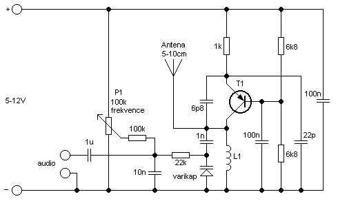
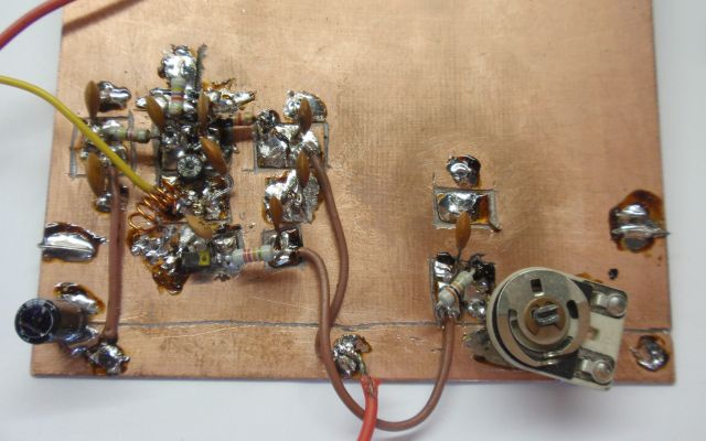
This simple transmitter allows you to broadcast in the 87.5-108 MHz FM radio band. It consists of a simple oscillator using a silicon planar RF PNP transistor. The antenna is directly connected to the oscillator. Due to the large amplitude of the RF voltage, an antenna length of about 5-10 cm is sufficient. I used insulated 7 cm long, 1 mm diameter copper wire. I omitted the tuning capacitor, which is common in most eavesdropping devices and small transmitters because it greatly complicates tuning. Based on my own experience, I know that the operating frequency will change if you get close to such a capacitor. This is why I chose to use voltage tuning with a voltage-controlled oscillator (VCO). Instead of a tuning capacitor, a varactor diode (capacitor diode) is used, which changes its capacitance by changing the reverse DC voltage. We can tune the operating frequency by changing the DC voltage using a trimmer P1. The varactor diode also provides frequency modulation.
Tuning: Set P1 to the center position. Turn on the FM radio and tune it to an unused frequency in the 87.5-108 MHz band. You will hear noise. Turn on the transmitter and first roughly tune the operating frequency by stretching the turns of coil L1. Then fine-tune the frequency using P1. A correct tuning is indicated by the radio becoming quiet. You can then connect an audio source to the input (e.g., a cassette player, CD or MP3 player, record player, audio output of a PC or laptop, etc.). Tuning can also be performed with a signal source already connected. Circuit
It can be powered from the 5V USB port available on your PC or laptop.
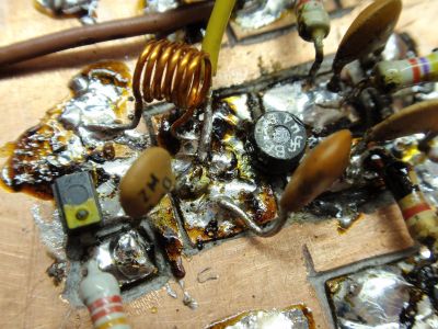
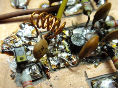
Inductor L1 is air-core, with six turns of 0.5 mm diameter wire wound on a 3 mm diameter coil. Closely wound L1 results in higher inductance and lower frequency. Stretched L1 results in lower inductance and higher frequency.
The varactor diode is arbitrary, covering a range of approximately 5-20 pF, such as MV2105, MV2109, and MV209. I used a Tesla-made varactor diode, MV209, with yellow paint on the cathode. The transistor is a high-frequency planar PNP type, such as BF970, BF979, BC559, or similar. You can also use transistors in different package types. The drawback of the circuit is its sensitivity to changes in the supply voltage (which alters the varactor diode voltage, thus changing the operating frequency). The antenna is directly connected to the oscillator, so the frequency will shift if you touch it or bring it close to a conductive object. However, despite its simplicity, the circuit works surprisingly well, with a range of approximately 20 to 100 meters.
You can use a 5-12V power supply or a battery. There should be no ripple in the power supply voltage; otherwise, you may hear it on the receiver.
- 1-watt quadruple FM transmitter
- USB FM Transmitter MAX2606
- Phase-locked loop frequency modulation transmitter
- FM transmitter
- RS-485 Basics: When Termination Is Required, and How to Do It Correctly
- Multifunctional miniature FM transmitter composed of discrete components
- FM transmitter circuit with power up to 300mw made of discrete components
- FM transmitter circuit made with TA7335 integrated circuit
- MICRFl02 ASK 470~300 MHz Transmitter
- XEl201A FSK 300~500 MHz transceiver
- NE555 exponential voltage controlled oscillator circuit diagram
- Voltage controlled oscillator circuit composed of monostable circuit
- Linear Triangular Wave Square Wave Voltage Controlled Oscillator
- Voltage controlled oscillator circuit diagram using comparator
- Digital voltage controlled oscillator circuit diagram
- Voltage controlled oscillator circuit diagram with output double limiting
- Triangular wave-square wave voltage controlled oscillator circuit diagram
- Simple voltage controlled oscillator circuit diagram
- Franklin push-pull reactive voltage controlled oscillator circuit diagram
- VF linear voltage controlled oscillator circuit diagram


 京公网安备 11010802033920号