Class A headphone amplifier
Source: InternetPublisher:46PaPjF9R1 Keywords: Headphone Amplifier Updated: 2026/03/10
Class A headphone amplifier
This Class A headphone amplifier can output up to 0.5W of power to 32-ohm headphones. I built this amplifier for dynamic headphones based on my correct audio design rules. Those familiar with my design will realize that this is much more than just a headphone amplifier. It's a pure Class A design, incorporating an unprecedented servo loop that is not part of the audio signal chain in any way. The sound of this Class A headphone amplifier is stunning.
Capacitors in the audio signal path are problematic. Even the best silver mica or polyester capacitors exhibit nonlinearity at low voltage levels. Capacitors belong in the power supply section, not elsewhere. Using capacitors to compensate for amplifiers often means the amplifier is otherwise unstable, has right-half-plane poles, and is therefore a poor design.
Transformers in the audio signal path are even worse: nonlinearity in the gain structure, parasitic capacitance between windings, impedance problems... Transformers are linear power sources, not elsewhere.
Extremely high open-loop gain: Absolutely terrible!!! This basically means any circuit containing an operational amplifier. Operational amplifier circuits with an open-loop gain of 10,000 or higher require a huge amount of feedback to make them usable. While this reduces THD, intermodulation products, especially transient intermodulation products, are far above what they should be.
Servo loops must never be located in audio feedback loops. This rule is also very important. My two favorite high-end audio electronics manufacturers place servo loops at the negative input of their amplifiers. Most other manufacturers that use servo loops do the same. The output impedance of the operational amplifier used for servo loops is not low enough to make it suitable for this purpose. Furthermore, when connected in series with a gain resistor on the negative input, the dynamic output impedance of the operational amplifier adds non-linearity to the audio.
This makes designing ultra-high-quality audio equipment difficult. My design goals in this amplifier are: to keep the gain low per stage, to keep all stages in Class A, and to prevent the differential front end from approaching clipping by using current sources. Servos help prevent DC voltage at the output due to the low overall gain and minimal feedback of the amplifier. Generally, if the open-loop gain is to be kept low to eliminate all or most transient intermodulation distortion, then the amplifier circuitry must be extremely linear and distortion-free. Otherwise, you end up with something with poor measurements and performance.
circuit
The schematic of the standard (non-bridged output) version of the headphone amplifier is shown in Figure 1. The amplifier's open-loop gain is approximately 35. Even with feedback removed, the THD is less than 0.01%. This is significant because the more linear the amplifier is without feedback, the more the THD, IM, and TIM distortion decrease to immeasurable levels after adding feedback.
The first stage is a dual-FET fully differential, fully balanced front end. The quiescent current is a total of 2mA for each dual FET (1mA per FET), and 4mA for the entire front end stage (including the two dual FETs). The dual FETs generate the bias, driving the second stage and keeping it and the resulting output stage always in Class A. The FETs are ultra-low noise dual units designed specifically for audio applications. The total voltage gain of the first stage is 50.
The second stage is the driver stage. It is a standard Class A voltage amplifier—used as a voltage shifter in this case. The voltage gain is 0.5, and the quiescent current is 4.3mA.
The push-pull Class A output stage is a series of emitter follower current buffers connected in parallel. The voltage gain is 0.9, and the current gain is 75. The quiescent current is 15mA per transistor (or 60mA for the eight transistors on the +16VDC rail and 60mA for the eight transistors on the -16VDC rail). I designed the output stage to operate in the sweet spot region of these transistors, i.e., 15mA each. Yes, it will get hot; it's meant to get hot (but not hot enough to require a heatsink). It's impossible to build an amplifier with an output impedance of less than 0.1 ohms without consuming a considerable amount of current.
The servo circuitry is new: most servo designs (such as Mark Levinson and Krell) feed the DC servo output back to the amplifier's output. I don't like that. This introduces operational amplifier noise and nonlinearity into the audio loop.
My servo feeds back to a first-stage dual-FET current source. Like all servos, it's an integrator. Due to the relatively large integrating capacitor and 1 megohm resistor, the filter operates at a frequency of 0.05 Hz. Even using a standard operational amplifier, the servo's noise is in the tens of microvolts range and doesn't significantly affect the operation of the current source.
The servo operational amplifier in this amplifier measures any DC at the output, integrates it, and applies it to the midpoint between the two LEDs. The voltage of the LEDs does change slightly relative to the current, about 3% or 4%, which is sufficient for the servo to operate. Note that if the transistors or resistors are poorly matched, the servo will not work because its total control range is at most 10%. Most standard servos (such as Mark Levinson or Krell servos) have a wider range.
For high-impedance headphones, a small amount of DC will not damage them. For low-impedance Grados, even 0.1VDC for an extended period will certainly damage and/or alter the sound. If all parts are manually matched, the power supply is identical, and all resistors are of high quality, the amplifier should be stable and not drift. In this case, the servo can be omitted or replaced with a 20K trimmer potentiometer wired from +16VDC to -16VDC, with the slider connected to the DC adjustment pin. The prototype used 0.05% tolerance resistors, and I manually matched the transistors. The output DC was less than 6mV and remained perfectly stable for several months after I owned the unit.
Schematic diagram of the output of the bridged version amplifier.
Figure 2
This amplifier delivers approximately 0.5W of power to a 32-ohm load. In the classic Class A definition, the top transistor would source 120mA and the bottom transistor would sink 0mA. However, the two 3k resistors in the second stage effectively prevent either transistor group from completely shutting off by keeping the relative stages at an absolute minimum of 5mA. In any case, the sound is incredibly loud when outputting 0.5W of power to the Grados.
The balanced bridged output version of the amplifier (Figure 2) is suitable for headphones that can be wired as dual-mono (see the appendix for instructions on converting standard Grado SR-80 headphones to dual-mono). It features twice the voltage swing, twice the slew rate, and four times the output power (competing with the $2,600 HeadRoom balanced Max amplifier).
Power supply schematic diagram.
The power supply overshoot regulation (Figure 3) is so excessive and unnecessary that most, if not all, builders of this amplifier wouldn't even notice the difference. However, this design offers several advantages. First, it's a dual-track design. Due to the amplifier's low open-loop gain, its common-mode rejection of the power supply is poor. However, if the + and - voltage rails move up and down by the same amount, there is no bias drift.
Thanks to the pre-regulator, total line/load variation is less than 0.0001%. Fast capacitors allow the power supply to respond quickly and in a controlled manner to highly reactive loads like Grados. The operational amplifier outputs are active in both directions; they can push or pull to keep the power supply just at the right point. The power supply design is an attempt to produce the best I could. It's even quieter than a battery.
structure
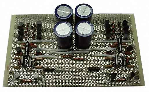
The prototype was built using point-to-point wiring to keep it compact and small. The layout is exactly the same as shown in the schematic, which is why the board only has one layer. Although the amplifier is easy to build without a PCB, I designed a board for it. Each board (two are needed for the standard amplifier, four for the bridged version) measures 3.3 inches x 3.8 inches. In a few months, I may redesign the board for one of the systems and send the files and retrieve the board via the internet (e.g., expresspcb.com).
The total control range of the servo is at most 10%, therefore some servo-related components must be closely matched to achieve optimal servo operation. The 500-ohm resistor, 1.6V LED, bias transistor, and second-stage transistor must be matched to within 0.5% or even 0.25% for optimal servo operation (dual FETs are already matched). To match the LED, connect one in series with a 10kΩ resistor to 15VDC and measure the voltage across it. Perform this operation on several LEDs and select the closest match.
Circuits used to match NPN and PNP transistors.
I used a Tektronix curve tracer to match the transistors. Figure 4 shows two circuits for matching the beta (gain) of NPN and PNP transistors using only one voltmeter. Simply measure (and match) the collector-to-ground voltage of each transistor. For NPN, this should be in the range of 10V to 11V; for PNP, it should be in the range of 5V to 6V.
There are no substitutes for FETs. The PNP and NPN transistors in the prototypes were the MPS8099 and MPS8599. Onsemi has discontinued them, but they are still widely available. I now buy all the transistors from MCM Electronics through their website. I've had too much trouble dealing with other companies. 2SA1015 PNPs are $0.46 each; 2SC1815 NPNs are $0.41 each. 2SJ109 p-channel dual FETs are about $6.50; their n-channel counterparts are $5.90. When you add them all up, it's still below the minimum order from MCM, so you have to buy something else.
The assembled PC board.
The high-speed 5uF capacitors in the power supply are not critical. They satisfy the "enthusiasts" in audio. These capacitors have a slew rate (dv/dt) that is about four times that of standard capacitors. They were purchased from the Illinois Capacitor Company for $7.50. Similarly, the operational amplifiers in the power supply are not critical. In the prototype power supply, I used Apex PA09s with a slew rate of 400V/μS, each costing $167 (remember, I'm crazy). The average person should use Texas Instruments OPA549s (10V/μS), each costing $11. LM3xx regulators are used for cooling (each dissipating at least 3W, 6W for the bridged version of the amplifier).
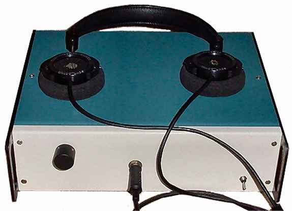
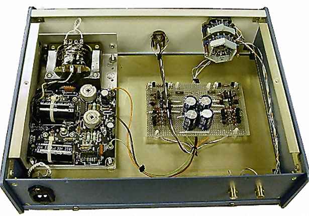
The housing is a Mod.U.Line (part number 03-1209-BW) from Precision Fabrication Technologies Inc., available from Newark Electronics. They cost around $85 each now. The aluminum housing is easy to use, easy to punch, and maintains a good paint finish. The headphone jack is a cheap Radio Shack product. Although it works fine, I later acquired some Neutrik connectors, which I will install at some point. Theoretically, there is a ground loop between the RCA jack on the rear panel and the headphone jack on the front panel. Although the 60 Hz hum is below approximately 110 dB, the Neutrik jack is isolated, which will eliminate this issue.
Inside the amplifier chassis.
The amplifier's output is voltage-limited (not current-limited) because the second stage exhausts the voltage swing—typically around 6V rms. For a 32-ohm load, the maximum output power is 1.125W (0.1875A). For a 300-ohm load, such as the Sennheiser HD600, the maximum output power is 0.125W (0.02A). To increase the maximum output voltage to, for example, 10V rms, try increasing the supply to ±20VDC and changing the 500-ohm resistor in the current source/sink to 600 ohms (or ±24VDC and 700 ohms—but be careful not to burn out the output transistors).
The bridged version will output 4.5W to the 32-ohm Grados and 0.5W to the 300-ohm Sennheiser HD600. At full power, the amplifier does indeed exit Class A, but at levels that will burn your ears anyway.
result
Adjustment: In the power supply, adjust the top 20K trimmer potentiometer to +24V at the tap after LM317. Then adjust the bottom 20K trimmer potentiometer to -24V at the tap after LM337. (Note: ±48V taps are for reference only; they are not actually used by the amplifier.) If the servo has been replaced with a 20K trimmer potentiometer, adjust the trimmer to make the output measurement 0VDC. Any value below 25mV is acceptable.
I listened to the balanced HeadRoom Max at the Home Electronics Show. The low-frequency bass impact was missing from that device. The same thing happened when I listened to the BlockHead ($3333) and compared it to my unbalanced/balanced amplifier. Without that punch, it wasn't as fun to listen to.
This amplifier makes the Grados and Etymotic Canalphones sound fuller and more direct than the built-in headphone jacks on various players—the bass has an unprecedented explosiveness. And the sound image moves from around your head to the center of your nose. The Etymotics sounds a bit thin and distant compared to other amplifiers. Overall, I have to say this amplifier produces a much more solid bass—like putting a microphone in front of the double bass rather than inside it.
- Gain Cloning Power Amplifier LM3886
- 18-watt audio amplifier
- TDA2002 8W Car Radio Power Amplifier
- 50W LM3886 Power Amplifier
- TDA1013 4.2 Watt Power Amplifier
- Hybrid tube headphone amplifier
- Miniature audio amplifier
- Portable microphone preamplifier
- 4-channel stereo selector
- TDA1521 dual channel power amplifier OTL connection and OCL connection
- NE5532 designed HIFI headphone amplifier circuit diagram
- Keyed volume headphone amplifier
- Headphone Amplifier
- Convert an idle VCD machine microphone preamplifier into a headphone amplifier
- Typical circuit diagram of LM4921 for two-channel headphone amplifier
- NE5532 high-fidelity stereo headphone amplifier circuit diagram
- ECC822 tube headphone amplifier circuit diagram
- transistor headphone amplifier
- LA4461N audio IC circuit
- TDA2030 audio power amplifier circuit diagram


 京公网安备 11010802033920号