Hybrid tube headphone amplifier
Source: InternetPublisher:78kRtxyqh Keywords: Vacuum tubes headphone amplifiers Updated: 2026/01/13

Hybrid tube headphone amplifier
This is a simple and easy-to-build hybrid tube headphone amplifier, constructed around 12AU7/ECC82 vacuum tubes. I've always been interested in tube amplifiers, but most DIY kits are very expensive and use high voltage. Therefore, I decided to build a low-cost amplifier with minimal parts requirements to drive a pair of 32-ohm Grado headphones.
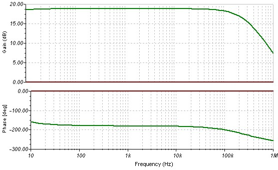
I've built several Yaha amplifiers based on the fa-schmidt design, along with a Szekeres MOSFET follower, and I wanted to know how they would sound together. So, I built the schematic into TINA-TI, a free SPICE-based program for testing circuits before building, and the results were remarkable. There was nearly 20dB of gain from a 13VDC supply in the 20Hz-100kHz range.
As you can see in the schematic and parts list, there are fewer than 30 discrete components, most DIY enthusiasts will have them from other builds as spares. I chose the 12AU7/ECC82 vacuum tube because it can be driven at low voltages, and the filament voltage is 12.6 volts, so no further voltage adjustment is needed. I used a 1/4-watt resistor in the first stage and a 2-watt resistor in the second stage. The 2-watt resistor might be too large, but I didn't want to replace it later. 20-ohm resistors must be at least 5 watts, and wire-wound resistors should not be used because their inductive characteristics will distort the response curve.
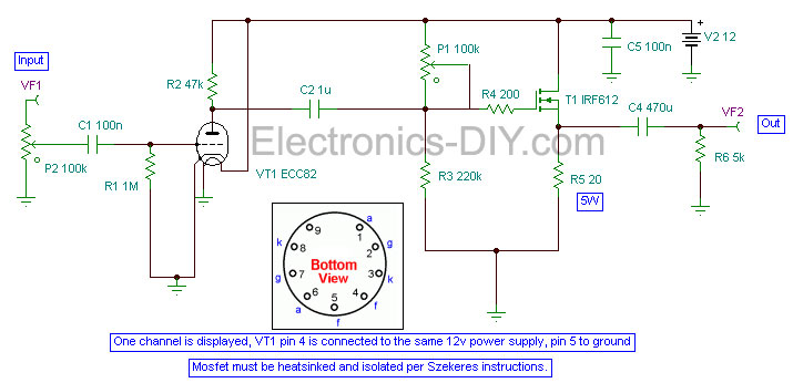
Figure 2: Schematic diagram of a 12AU7 vacuum tube/IRF612 MOSFET headphone amplifier
Table 1: Parts List - 12AU7 / IRF612 Headphone Amplifier
100,000 euros
100 Nafa
100 Nafa
1 megaohm
1 microgram
20 ohms 5 watts
200 ohms 2 watts
220 kΩ 2W
470 microfarads 50 volts
47,000 euros
5,000 euros 2 watts
12AU7 / ECC82
IRF612
LED base
led
9-needle socket
Additional Notes - Parts List:
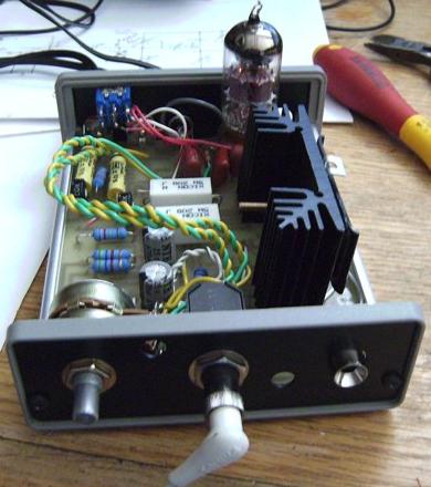
The heatsink must dissipate approximately 3 watts, therefore requiring 2.5-3 square inches; smaller is possible if a fan is used. Use thermal paste, mica insulator, and insulating washers. The MOSFET pins are at (12-13VDC).
Chassis optional, with planned ventilation.
This 13VDC switching power supply can heat the filament between 12 and 13 volts. The power plug is a standard Radio Shack DC plug.
The MOSFET (T1) can be replaced with IRF510, IRF610 or IRF611.
Construction - Vacuum Tube/MOSFET Hybrid Headphone Amplifier
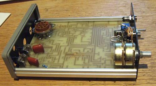
For the housing, I used a Lansing MicroPak "C"; I found it on eBay for about $8. The item was some leftover stock from a surround decoder, complete with RCA connectors and a pre-punched panel. The tube socket should be 9-pin; this one was for an older pixel tube, so it has more holes, but 9-pin is a perfect match.
Photo 1: Lansing MicroPak casing and PCB
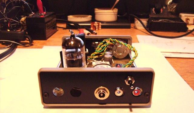
I'm using RCA connectors for inputs and 1/4-inch jacks for outputs, to accommodate my Grado SR125 headphones, and the holes on the panel are stamped for the 1/4-inch jacks.
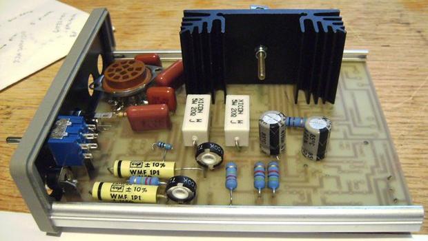
The PCB has pre-existing pads and ground bus, which determines the placement of components. If you are building on a prototype board, ensure that space is left for heatsinks and 20-ohm resistors for heat dissipation. Ensure that the MOSFETs are insulated from the heatsink using mica and use thermal paste to improve heat transfer. The MOSFET pins are at 12-13 volts; shorting them to ground will damage the power supply and the component.
Photo 2: Construction of the hybrid headphone amplifier
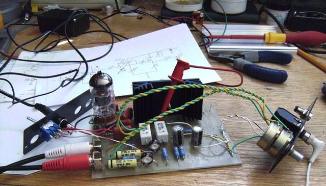
After all components were soldered, I performed a smoke test on the unit and made the necessary corrections.
Photo 3: Smoke test of vacuum tube/MOSFET hybrid amplifier
The vacuum tube heater draws 150mA at 12.6 volts, and the entire amplifier draws 580mA at startup, stabilizing at 550mA after the vacuum tube warms up; this takes a few seconds. I used a Canon AD-360U switching power supply from their small inkjet printer. Since the MOSFET drain is directly connected to the positive rail, any noise is amplified. The power supply is virtually silent.
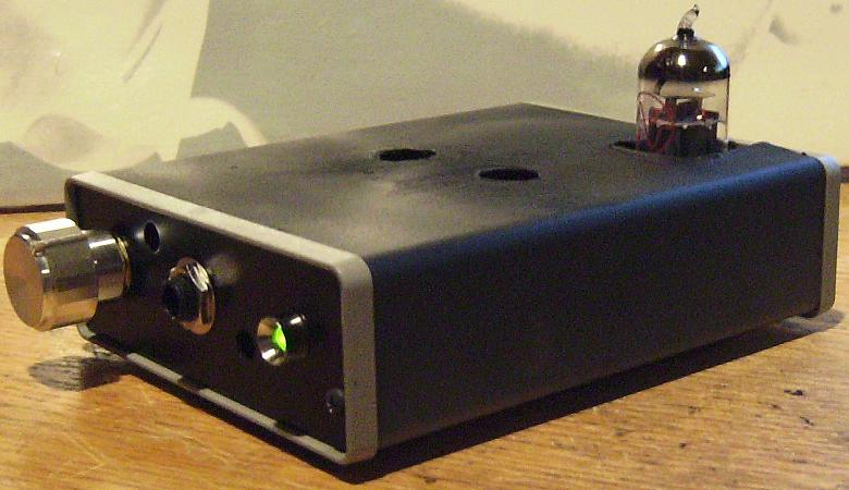
Photo 4: Hybrid Headphone Amplifier - Front View
Photo 5: Hybrid Headphone Amplifier - Rear View
I used a 12V muffin fan that drops to 9V to cool the amplifier. Two holes on the top allow air to rush in, and existing holes on the front and rear panels allow for good airflow.
Photo 6: Vacuum tube/MOSFET hybrid headphone amplifier
Measurement - Vacuum Tube/MOSFET Hybrid Headphone Amplifier
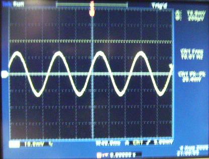
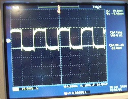
Here are some oscilloscope screenshots showing a 10 Hz sine wave response and a 100 Hz square wave response. Performance is very consistent, with the voltage remaining the same for most of the sweep. The TINA curve shows a gain of approximately 19 dB over the audible spectrum. The sound from my Grado SR125 headphones is clear and the bass is tight. Considering the low voltage and low component count, this amplifier is quite good. It may not be true audiophile quality, but it costs an average of $40 or less.
Photo 7: 10Hz sine wave
Photo 8: 100 Hz square wave response
This amplifier is ideal for novice builders, and components are available at Mouser and DigiKey. You can substitute other MOSFETs as long as the resistors are similar and the internal capacitance doesn't affect the response curve. It's best to build the schematic using TINA-TI and make any changes so you can check the AC output before building. This will save you a lot of time.
Finally, make sure not to plug your headphones into the jack when the amplifier is on or off. This amplifier, along with other DIY builds, experiences a large current surge when it is turned on or off, which could damage your headphones if you're not careful.
- Gain Cloning Power Amplifier LM3886
- 2-watt mini box amplifier
- 60W power amplifier
- Class A headphone amplifier
- High-performance stereo audio amplifier using LM3886
- Portable headphone amplifier
- Connection between power supply and voice integrated circuit
- Simple and easy to make TDA2003 power amplifier circuit
- TA7233 audio power amplifier circuit diagram
- Upgrading the negative feedback circuit of the MT12 tube amplifier
- Circuit diagram of a tube 40W amplifier
- NE5532 designed HIFI headphone amplifier circuit diagram
- Keyed volume headphone amplifier
- 2x80WHI-FI power amplifier 01
- A HI-FI tube power amplifier 02
- A HI-FI tube power amplifier 01
- High power tube power amplifier 02
- Production of small tube amplifier 02
- 60Wx2 linear standard tube amplifier
- Typical circuit diagram of LM4921 for two-channel headphone amplifier


 京公网安备 11010802033920号