Lightning detector
Source: InternetPublisher:wcssWI6DN Keywords: detector Updated: 2025/12/16
Lightning detector
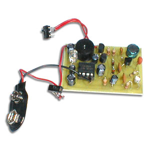
This DIY lightning detector circuit is a highly sensitive electrostatic discharge detector that provides early warnings of impending storms before a ground-to-air strike occurs due to an intercloud discharge. An antenna consisting of short wires can detect storms within a two-mile radius. The circuit provides an audible warning sound from a piezoelectric buzzer or flashing LEDs for each detected discharge, giving you advance warning of the approaching storm so you can take preventative measures.
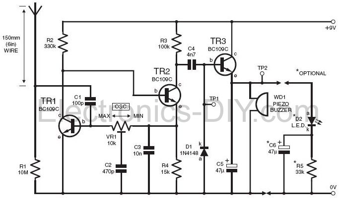
The main feature of the lightning detector is that the circuit can be configured to oscillate near self-excitedly, with its relaxation optimized by the bias resistor values shown in the circuit diagram. The oscillator is DC-coupled, with feedback routed from the collector of TR1 to the base of TR2, while the overall loop gain is set by a multi-turn (12, 18, or 22) preset potentiometer VR1.
Lightning detector settings
To set up the lightning sensor, adjust the preset VR1 to generate oscillation by monitoring test point TP1. TP1 should be approximately 7V peak-to-peak. Test point TP2 should be +6V DC. Now slightly adjust VR1 back to stop the oscillation; touch the antenna side of C1 several times with a screwdriver; the alarm should sound for 1 or 2 seconds and then stop. If it continues to sound, make a very small adjustment and check again. Another method is to electrostatically charge a plastic ruler and then bring your finger close to discharge it, about two meters away from the antenna.
Lightning detector schematic diagram
Lightning detector diagram
Powered by a 9-volt battery, the lightning detector circuit consumes approximately 600 microamps in standby mode. With continuous power, it can provide uninterrupted monitoring for a full year. When an alarm is triggered, the current will rise to 4 milliamps, depending on the low-current emitter WD1. A minimum 3-volt device is required to achieve a good output level, which will generate a "pinging" alarm to provide real-time alerts for any electrostatic pulse activity.
- Simple RF Power Meter
- Simple Digital Oscilloscope
- Dedicated 2.5 GHz frequency counter
- Method for measuring leakage current through insulation resistance
- The making of watermelon ripeness measuring instrument
- Lossful and lossless current test methods
- Small capacitance measurement circuit
- Simple Field Strength Meter Production
- Simple coil turns measuring instrument based on 555
- Transistor detector circuit
- Precision threshold detector circuit diagram
- Level detector circuit diagram
- Audio signal detector circuit diagram
- Positive peak detector circuit diagram D
- Wide range peak detector circuit diagram
- Analog signal peak detector circuit diagram with digital hold function
- High frequency peak detector circuit diagram
- Large bandwidth peak detector circuit diagram
- Dual level detector circuit diagram
- FT-1R optical signal detection circuit diagram using TGS as detector


 京公网安备 11010802033920号