Design of short-distance wireless communication circuit based on single-chip microcomputer
Source: InternetPublisher:兰博 Updated: 2021/01/10
Short-distance wireless transmission has the advantages of strong anti-interference performance, high reliability, good security, few restrictions on geographical conditions, and flexible installation. It has broad application prospects in many fields. Low power consumption and miniaturization are the actual needs of users for current wireless communication products, especially portable products. Short-distance wireless communication has gradually attracted widespread attention. Common short-distance wireless communications include 802.11-based wireless LAN WLAN, Bluetooth (blueTooth), HomeRF and Europe's HiperLAN (high-performance wireless LAN). However, their hardware design, interface methods, communication protocols and software stacks are complex and require specialized development. system, the development cost is high, the cycle is long, and the final product cost is also high. Therefore these technologies are not widely used in embedded systems. Ordinary RF products do not have these problems, and the short-range wireless data transmission technology is mature, simple in function, and easy to carry, making it widely used in embedded short-range wireless products.
Clock circuit and reset circuit of the microcontroller: In the design of the clock circuit of the microcontroller, the crystal oscillator frequency is selected to be 11.059 2 MHz, the communication rate between the PC and the microcontroller is agreed to be 9 600 b/s, and the corresponding capacitor is selected to be connected to the clock pin of the microcontroller to form a clock loop. . In the reset circuit design, the reset pin and the corresponding capacitor and resistor are used to form the reset circuit. The principle circuit of the interface between the microcontroller and PTR2000 is shown in the figure.
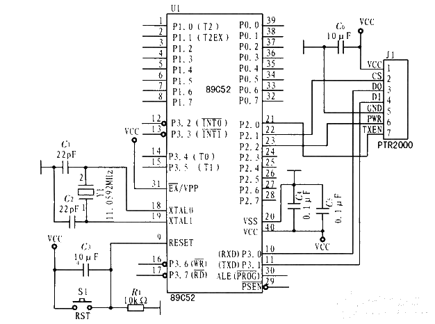
MCU and PTR2000 interface circuit: AT89C52 MCU mainly completes data collection and processing, sends data to the PTR2000 module, and receives data transmitted by the PC through PTR2000. The PTR2000 module connected to the microcontroller mainly modulates the data to be transmitted by the microcontroller into a radio frequency signal, and then sends it to the PTR2000 module on the PC side. At the same time, it receives the radio frequency signal transmitted by the PTR2000 module on the PC side, and modulates it into a TTL signal that the microcontroller can recognize and sends it to Microcontroller. The RXD and TXD pins of the microcontroller are connected to the DO and DI pins of the PTR2000 respectively to realize serial data transmission; the three pins TXEN, CS, and PWR, which determine the working mode of the PTR2000 module, are respectively connected to P2 of the I/O control port of the microcontroller. 0~P2.2 are connected. When PTR2000 is working, its working mode is controlled in real time by the operation control program in the microcontroller.
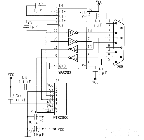
The interface circuit design first requires level conversion. The serial port of the PC supports the RS-232 standard, while the PTR2000 module supports the TTL level. The MAX232 device is selected for level conversion between the two. The interface circuit is shown in Figure 3. The PTR2000 module performs serial input and output, and the pins DI and DO are connected to the PC serial port through level conversion devices; the PTR2000's low-power control pins. PWR is connected to high level VCC, that is, PTR2000 is fixed to work in the normal working state; channel selection pin CS is connected to GND low level, that is, fixed communication channel 1 is used, fixed to work at 433.92 MHz; the RTS signal of the PC serial port controls the TXEN pin , to determine when the PTR2000 module is in the receiving and transmitting state. The transmission rate of the PC and serial port is set to 9 600 b/s, which is consistent with the microcontroller.
- How to construct a small welding machine using a 5 amp transformer and a high current bridge rectifier?
- Share an electronic touch organ circuit
- Using BMP280 to make a weather station
- Build a Raspberry Pi-based QR code scanner
- How to create a digital watch using YAKINDU Statechart Tools
- Making a Smart Blind Pole Using Arduino Uno and Ultrasonic Sensor
- Design a BLE thermos cup using M5Stack
- Circuit diagram of intermittent cockroach killer
- Production of electric water bottle energy saver
- Making an Off-Grid Solar PV System
- How does an optocoupler work? Introduction to the working principle and function of optocoupler
- 8050 transistor pin diagram and functions
- What is the circuit diagram of a TV power supply and how to repair it?
- Analyze common refrigerator control circuit diagrams and easily understand the working principle of refrigerators
- Hemisphere induction cooker circuit diagram, what you want is here
- Circuit design of mobile phone anti-theft alarm system using C8051F330 - alarm circuit diagram | alarm circuit diagram
- Humidity controller circuit design using NAND gate CD4011-humidity sensitive circuit
- Electronic sound-imitating mouse repellent circuit design - consumer electronics circuit diagram
- Three-digit display capacitance test meter circuit module design - photoelectric display circuit
- Advertising lantern production circuit design - signal processing electronic circuit diagram


 京公网安备 11010802033920号