The Difference Between PSR and SSR in Bias Power Supply Design
Source: InternetPublisher:闪电杰克 Keywords: Primary side regulation secondary side regulation Updated: 2025/08/22
1. Introduction
For bias supplies with power levels less than 10W, efficiency and cost are the most important design considerations. In this article, I will compare two control schemes—primary-side regulation (PSR) and secondary-side regulation (SSR)—and offer some suggestions for achieving a more efficient and cost-competitive design.
The classic flyback topology shown in Figure 1 remains the most popular topology for power supplies below 10W, not only because its small number of external components helps us achieve a very competitive bill of materials (BOM) cost, but also because the flyback topology can easily achieve multiple outputs, which is a key specification in bias supply design.

Figure 1: Classic flyback topology
2. Secondary side regulation
Figure 2 shows a typical SSR control block diagram. Output voltage feedback is required to stabilize the output voltage. For safety reasons, isolated power supplies require non-current feedback; the output must be electrically isolated from the AC input. Traditionally, optocoupler transistors provide this isolation. Compared to the classic flyback topology, the main difference is the addition of an optocoupler (such as the TI TL431) and multiple resistors and capacitors to form the feedback loop and error amplifier compensation circuit.

Figure 2: Typical SSR flyback block diagram with single output
With optocoupler feedback, it is possible to select which output to regulate, or to weigh the impact of each output on the loop demand by connecting a sense chain from each output, as shown in Figure 3. Therefore, we can easily achieve load regulation within ±1% if we use the SSR control law.
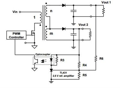
Figure 3: Block diagram of an SSR with multiple outputs
3. Primary side regulation
Compared to the SSR topology, the PSR control method eliminates the optocoupler and compensation components (as shown in Figure 4). The magnetic field in the transformer provides feedback. While resistors and capacitors are relatively inexpensive (though the cost of the error amplifier and optocoupler is not insignificant), this approach does save cost and printed circuit board (PCB) area. The aging characteristics of optocouplers can reduce the reliability of the design, so fewer components can increase the mean time between failures (MTBF).
On the other hand, PSR controllers are typically internally compensated, which saves time and effort in control loop design. For applications with high surge or isolation voltage requirements, reducing the number of components crossing the isolation barrier reduces the number of areas where failure can occur.
For PSR controller cross-regulation, the most heavily loaded output sets the loop requirements. If the load is lighter, the other outputs may not regulate well. And because most PSR controllers use "knee sampling" for feedback, they operate only in discontinuous conduction mode (DCM). The output voltage ripple will be higher than in continuous conduction mode (CCM).

Figure 4: Block diagram of a PSR with a single output
Table 1 compares some key features between PSR and SSR control laws.

Table 1: Quick comparison of key features of PSR and SSR controls
4. New reference design
This universal input, 10W, high-efficiency, low-cost power supply reference design with isolated multiple inputs is designed for appliance bias supplies and operates in constant voltage (CV) and constant current (CC) flyback modes using TI's UCC28911 controller. This high-voltage switcher integrates a high-voltage power FET and a controller using PSR to support magnetically induced output voltage regulation via the transformer bias winding. This sensing eliminates the need for a secondary-side reference, error amplifier, and opto-isolator for output voltage regulation. The magnetic sampling scheme allows operation only in DCM, so if the device does not sense a zero-crossing detector (ZCD) event, such as when the auxiliary winding voltage is high after transformer demagnetization, the modulator adjusts the frequency and peak current in different load regions to maximize efficiency across the entire operating range. Intelligent management of control logic power consumption and the high-voltage current source for startup, which shuts down during operation with very low leakage current, allows the design of a converter with very low standby input power.
Key highlights of this reference design are:
Over 75% low-load efficiency at 10% load
Standby power is less than 30mW at 90V input
Valley switching and frequency dithering to simplify EMI compliance
Figures 5 and 6 show a simple schematic diagram and efficiency curves, respectively.

Figure 5: Multi-output flyback converter based on UCC28911

Figure 6: Efficiency curves at 230V AC and 115V AC input
5. Summary
The flyback converter is the most popular topology for low-power isolated power supplies. While it allows for easy and cost-effective implementation of multiple outputs, this topology still suffers from poor transformer utilization and high AC resistance losses.
If you want good transient response performance and require high-precision output, the SSR control topology is more suitable. If the design is very sensitive to cost and standby power consumption, choose a PSR controller.
- LM317 overvoltage protection
- 50V 3A regulated power supply (using 2N3055)
- 0-30V/20A High-Power Regulated Power Supply (using LM338)
- Electronic fuse
- 0-28V 20A Adjustable Power Supply (Based on LM317 and 2N3055)
- 5V power supply with overvoltage protection
- Power LED driver circuit
- Charging monitor for 12V lead-acid batteries
- Dual USB charger with switching regulator
- Charge-coupled bidirectional power MOSFET relay
- Excellent performance household inverter power supply circuit
- Power supply circuit design optimized for digital light projectors
- Laser power circuit
- Single phase thyristor slotless nickel plated power circuit
- Additional power circuit design for USB devices
- Industrial four-way programmable controller power circuit
- ±15V active servo power circuit
- Neon light high voltage power supply circuit
- Common power circuits and applications 09
- Common power circuits and applications 08


 京公网安备 11010802033920号