Learn about undervoltage lockout of power supplies
Source: InternetPublisher:通通 Keywords: Undervoltage lockout UVLO Updated: 2025/09/19
I've been told that the human body thrives in an optimal environment between 21 ° C and 30 ° C, so inside TI's air-conditioned offices – set at 23°C year-round – the conditions are perfect for peak performance (at least, that's what my boss tells me).
However, during winter in the north, temperatures can drop to –20 ° C or lower. Even with multiple layers of clothing, the human body does not function well in these conditions: it can survive, but not at its peak performance.
The human body isn't the only thing affected by the conditions it operates in. Integrated circuits also operate best within certain temperature and supply voltage ranges. In this article, I'll discuss the latter and the related undervoltage lockout (UVLO) function.
How low can the voltage go?
As most electronics engineers already know, many integrated circuits include a UVLO function that disables the device when its supply voltage is too low for normal operation. Without a UVLO function, at low supply voltages, the device might do something, but we wouldn't be able to determine what. The UVLO function ensures that the device either operates according to its specifications or does nothing at all.
Low supply voltage can cause, among other things:
Bias circuit is not operating correctly.
Bandgap produces incorrect reference voltage.
· Logical function failure.
The power transistor is only partially turned on or off.
Many devices have UVLO thresholds below a few volts. Honestly, it's impressive that a device can do anything at such a low supply voltage. If you don't believe me, try designing an analog circuit that operates at 2V and see how we do.
Power devices face even greater challenges. When the supply voltage is low, you might be able to turn a power MOSFET on and off, but you won't be able to do it quickly. Typically, the MOSFET's on-resistance increases because the supply voltage is too low to generate a high enough gate-to-source voltage.
Some devices specify a recommended supply voltage range and UVLO threshold. Full performance is achieved only when the supply voltage is within this range. But what happens between the UVLO threshold and the recommended minimum supply voltage? Some TI power devices still operate within this range, but their performance is unspecified. This means that a buck converter still steps down, a boost converter still steps up, and a buck-boost converter still steps down, steps up, or steps down-boost, but the available output power may be less than the maximum power the device is capable of delivering.
In mission-critical applications, the UVLO threshold is often higher than the recommended minimum supply voltage—the device turns on only when full performance is available. This approach results in extremely robust system designs, but is generally not cost-effective for consumer products. It's like driving a car that stops working when the fuel level is low (but not empty). Keeping the car drivable—albeit with reduced performance—is more useful than having it suddenly stop working completely.
Figure 1 illustrates the typical operating state of a power device. You can see:
In the red region where V I < V IT (min), the device is inoperative and consumes minimum supply current.
· In the green region where V I > V REC (min), the device operates at full performance.
In the gray region where VIT(min) < VI < VIT(max), the device is either off (red) or on (yellow), but either state depends on the precise threshold of the UVLO function.
· In the yellow region where V IT < VI < V REC (min), the device is fully functional but its performance is not specified in the datasheet.
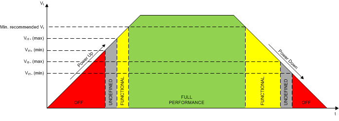
Figure 1: Typical UVLO behavior
Note that the rising and falling UVLO thresholds are different. This is because a well-designed UVLO function incorporates hysteresis. Why? Well, not only do comparator circuits typically benefit from hysteresis, but power devices, by their very nature, tend to draw significant current from the upstream power supply. Because there's always some resistance between the power supply and the device it's powering, the voltage seen by the UVLO comparator is always slightly lower than the voltage of the upstream supply (see Figure 2). When the voltage reaches the UVLO threshold, the device turns off, and the current flowing into it instantly drops to almost zero, causing the voltage seen by the UVLO comparator to immediately increase (because the voltage drop across the input resistance suddenly disappears when the input current decreases).
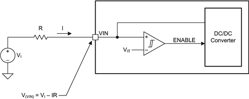
Figure 2: Equivalent circuit of a typical power device with UVLO function
If the hysteresis voltage is less than I × R, under certain conditions, the power management IC (PMIC) can turn on and off multiple times before finally shutting down permanently. At best, this can look unsightly. At worst, it can cause system-level problems. Figures 3 and 4 are scope diagrams illustrating this phenomenon.
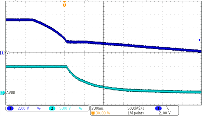
Figure 3: Low input resistance results in normal power-off behavior
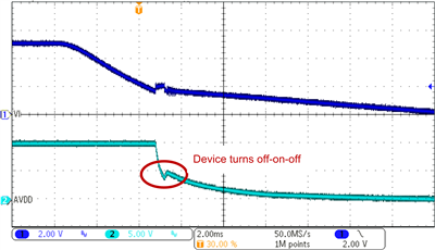
Figure 4: High input resistance causes irregular power-off behavior
Next time we design an application circuit, let’s take a moment to make sure we understand how the UVLO function works. For example:
Make sure we know the rising and falling thresholds of the circuit and their hysteresis;
Check to see if there is a region between the UVLO threshold and the recommended operating voltage range where the device may operate but may not provide all of its specified performance. Ensure your application can handle this region.
· Remember that the input current multiplied by the input resistance should be less than the UVLO hysteresis to achieve clean power-up and power-down behavior.
- Full-range adjustable power supply
- 1.5V to 5V converter
- 12V to ±30V DC converter
- Power LED driver circuit
- 1.5V to 5V converter
- 10A 1-30V Adjustable Power Supply Based on LM317
- USB Lithium Polymer Battery Charger
- How to design a suitable voltage reference for our circuit
- How to simulate our buck converter control loop?
- Re-examining the importance of current power monitors
- Importance of Voltage Supervisors and Output Topology Selection
- DC 12V to AC 100V inverter power supply circuit design
- Laser power circuit
- Dual adjustable power circuit
- Solar power circuit
- 2-phase CPU power supply circuit using HIP6302 and HIP6602 chips
- Industrial four-way programmable controller power circuit
- DC power supply circuit for semiconductor radio
- Common power circuits and applications 03
- Common power circuits and applications 01


 京公网安备 11010802033920号