How to use LILO LDO to improve system efficiency
Source: InternetPublisher:抄写员 Keywords: System efficiency LDO Updated: 2025/07/08
1. Introduction
LDO is a low dropout regulator, which is a low voltage difference linear regulator. This is relative to the traditional linear regulator . Traditional linear regulators, such as the 78XX series chips, require the input voltage to be at least 2V~3V higher than the output voltage, otherwise they cannot work properly. However, in some cases, such conditions are obviously too harsh. For example, when converting 5V to 3.3V, the voltage difference between input and output is only 1.7V, which obviously does not meet the working conditions of traditional linear regulators.
LDOs use transistors or field effect transistors (FETs) operating in their saturation region to subtract excess voltage from the applied input voltage to produce a regulated output voltage. The so-called dropout voltage is the minimum difference between the input voltage and the output voltage required for the regulator to maintain the output voltage within 100mV of its rated value. Positive output voltage LDOs usually use the power transistor (also called the pass device) as a PNP. This transistor allows saturation, so the regulator can have a very low dropout voltage, usually around 200mV; compared to the traditional linear regulator that uses an NPN composite power transistor with a dropout voltage of around 2V. Negative output LDOs use an NPN as its pass device and operate similarly to the PNP device of the positive output LDO.
2. High efficiency of LILO LDO
High efficiency in power supplies has historically been attributed to switching controllers or converters, while designers have considered linear regulators (LDOs) to have poor efficiency. However, linear regulator topologies have changed to single n-channel p-channel n-channel (NPN)/p-channel n-channel p-channel (PNP) or p-channel metal oxide semiconductor (PMOS)/n-channel MOS (NMOS) pass transistors to help achieve very low dropout voltages.

There are three major power trends in portable systems: lower bus voltage, compressed voltage conversion, and lower quiescent current (I Q ). These trends have led to the development of low-input low-output (LILO) LDOs.
As the bus voltage decreases, the minimum input voltage requirement of the LDO also decreases. As the bus rail drops below 1.5V, traditional LDO topologies begin to reach their limits because the input voltage rail powers all the internal circuitry. The decreasing input voltage has led to the growing popularity of LILO LDOs.
The LILO LDO uses an NMOS pass transistor and a bias rail to achieve a low voltage drop. The advantage of using an NMOS pass transistor is that it has a lower drain-source resistance (R DS(ON) ) than a PMOS. It also requires a positive gate-source voltage (VGS) to operate. Because of this topology, the bias rail is powered by a higher voltage and powers most of the LDO's internal circuitry, so the LDO can operate at a lower input voltage.
One of the main advantages of NMOS transistors is the low R DS(on), which allows for a smaller voltage drop per unit area compared to PMOS transistors, thereby achieving a smaller voltage drop while maintaining a small size. Figure 1 shows the typical topology of an NMOS LDO, from which it can be seen that the LDO requires a bias pin to operate properly.

Figure 1: NMOS LDO topology
As I said, the two advantages of LILO LDOs are lower input voltage and lower dropout voltage. The latter advantage improves efficiency, comparable to that of switch-mode power supplies. For all power supplies, we can calculate efficiency as a function of input and output power using Equation 1:

For a LILO LDO like the TPS7A10, we can calculate the efficiency using Equation 2 because the LDO has both a bias rail and an input voltage rail:
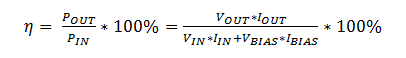 (2)
(2)
If the load current is much larger than I, the Q efficiency equation can be simplified as shown in Equation 3:
 (3)
(3)
We can see that the quickest way to improve the efficiency of an LDO is to bring the input and output voltages closer together by reducing the dropout voltage.
In portable electronics, it is common to use LDOs to power sensors because switching converters generate too much noise. Designers will use low I Q LDOs, believing they will extend the battery life of the system when the load is pulsing. This is not necessarily the most efficient solution; however, efficiency drops dramatically due to the high power dissipation during the load turn-on period.
Figure 2 shows two common power supply configurations used to implement portable systems. One uses a generic low I Q LDO and the other uses a low I Q LILO LDO. Comparing the power consumption between the two solutions, the generic low I Q LDO consumes 2.7 mW while the LILO LDO consumes 1.8 mW (see Table 1). Using the LILO LDO increases the efficiency from 55% to 82%, even though the LILO LDO has a higher total I Q.

Figure 2: Low IQ LDO vs. LILO LDO
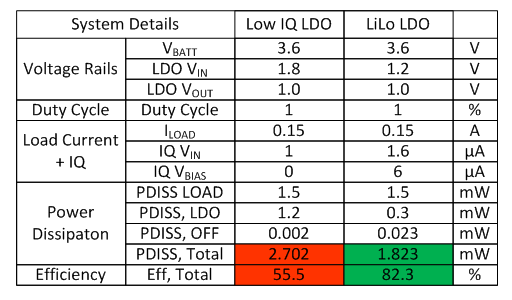
Table 1: Efficiency calculation
As we can see, if battery life and efficiency are our main concerns, then there are clear benefits to implementing a LILO LDO in a portable application. Reducing the difference between input and output voltages enables these LDOs to achieve efficiencies in excess of 80%. Once this is understood, we can select the appropriate LDO for our application.
- 12V dual power supply
- Fanless silent power supply
- 24V to 12V 400W DC-DC converter
- Automatic battery charger
- Solar charger for USB devices
- Atmel solar panel battery charger
- USB Chargers Then and Now: Type-C Meets Energy Efficiency Standards
- A flyback converter solution where two outputs are better than one
- Introduction to inverter circuit and principle
- Homemade small power inverter to solve power outage problems
- Solar power circuit
- 3v to 5v circuit diagram
- Commonly used power circuits in printers
- 2-phase CPU power supply circuit using HIP6302 and HIP6602 chips
- 2-phase CPU power circuit using HIP6302 and HIP6601 chips
- One of the transistor stabilized current power supply circuits
- Timing switch AC power circuit
- Industrial four-way programmable controller power circuit
- Household emergency power circuit 02
- ±5V, ±12V power circuit A


 京公网安备 11010802033920号