Working principle and usage of DC single-arm bridge
Source: InternetPublisher:风向西瓜 Keywords: DC bridge single arm bridge Updated: 2025/06/24
The DC bridge is an electrical measuring instrument that uses the comparison method for measurement. The central idea of the comparison method is to compare the measured value with the standard value to determine its value. It has the advantages of high test sensitivity and easy use.
1. Working principle of DC single-arm bridge
The single-arm bridge is also called the Wheatstone bridge. When the mid-value resistance needs to be accurately measured, the single-arm bridge is often used for measurement. Its principle is shown in Figure 1. In the figure, Rx is the measured resistance, G is the galvanometer, and Rl, R2, and R3 are adjustable resistors. When the relationship R1 R3 = R2 Rx is satisfied, the circuit reaches equilibrium. At this time, the current passing through the galvanometer is zero (the pointer does not move). We call R1/R2 the proportional arm and R3 the comparison arm. Figure 2 is a panel diagram of the QJ23 DC single-arm bridge. When measuring, you can select the appropriate comparison arm value multiplied by the multiple of the proportional arm based on a rough estimate of the measured resistance.
2. How to use the DC single-arm bridge
1) Before use, unlock the lock of the galvanometer and adjust the zero adjuster to adjust the pointer to zero.
2) Estimate the approximate value of the resistance to be measured, and then refer to
the table in the manual to select the appropriate proportional arm (multiplier) so that the various levels of the proportional arm adjustable resistance can be fully utilized to improve its accuracy.
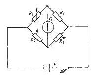
Figure 1 Principle circuit of single-arm bridge
3) When connecting the resistor, choose a thicker and shorter connecting wire and tighten the joint to improve the measurement accuracy as much as possible.
4) When measuring the resistance of an inductive circuit, such as a motor, transformer, etc., the power button should be turned on first, then the galvanometer button, and then the galvanometer button. After the measurement, the galvanometer button should be turned off first, then the power button, to prevent the self-induced electromotive force of the coil from damaging the galvanometer
5) After the bridge circuit is connected, if the galvanometer pointer deflects in the "+" direction, the resistance of the comparison arm should be increased; conversely, if the pointer deflects in the "-" direction, the resistance of the comparison arm should be reduced. Repeatedly adjust the comparison arm resistance until the pointer points to zero. Read the resistance value on the dial and multiply it by the magnification to get the measured resistance value.
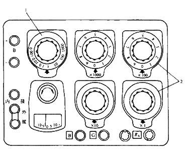
Figure 2 DC single-arm bridge panel Figure
1 - magnification knob 2 - scale arm reading plate
6) After the bridge is used, the lock of the galvanometer should be locked immediately to avoid damaging the suspension wire during the moving process. 7) Low battery voltage will affect the sensitivity of the bridge, so if the battery voltage is found to be low, it should be replaced in time. When using an external power supply, you must pay attention to the polarity and do not let the voltage exceed the specified value, otherwise the bridge arm resistor may be burned out.
- 500W MOSFET power inverter, 12V to 110V/220V
- 12V to 110V/220V 500W Inverter
- 0-28V 20A Adjustable Power Supply (Based on LM317 and 2N3055)
- High-current LM317 regulated power supply
- Car-mounted 12V DC to 50V DC converter
- Gate drive transformers vs. high-side and low-side drivers: Where is power supply design headed?
- Power Tip: What's the best way to drive a synchronous rectifier in a flyback power supply?
- Tips on how to optimize voltage monitors
- Mitigating Overheating in Hyperscale and Ultra-Scale FPGA Applications
- How to simulate our buck converter control loop?
- DC 12V to AC 100V inverter power supply circuit design
- DC 12V to AC 100V inverter power supply circuit design
- 2-phase CPU power circuit using HIP6302 and HIP6601 chips
- Single LTC power circuit
- Industrial four-way programmable controller power circuit
- Common power circuits and applications 06
- AC-DC conversion power supply-inverter power supply circuit
- Nine-speed adjustable DC power circuit
- 5V, 7.5V, 48V power circuit
- High quality power supply circuit schematic diagram


 京公网安备 11010802033920号