Numeric Comparator Basics
Source: InternetPublisher:萌面大虾 Keywords: Numerical comparator comparator Updated: 2025/08/08
A numerical comparator is a logic circuit that compares two numbers A and B to determine their size.
Figure 4.21 shows the logic diagram of a 1-bit comparator. It has two inputs, one for value A and one for value B. When comparing two values, there are three possible outcomes: A > B, A = B, and A < B. Therefore, it has three outputs.
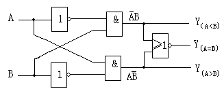
Figure 4.21 1-bit numerical comparator
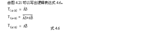
According to the logical expression 4.6, the truth table can be listed as shown in Table 4.12.
Table 4.12 Truth table of 1-bit numerical comparator
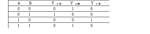
As shown in Table 4.12, when A < B (A = 0, B = 1), only Y(A < B) = 1; the remaining output terminals are "0"; when A = B (A = 0, B = 0 and A = 1, B = 1), Y(A = B) = 1; and when A > B (A = 1, B = 0), Y(A > B) = 1. This circuit can determine the magnitude of two 1-bit binary input numbers, A and B, based on the logical state of the output terminals. It performs the logic function of comparing 1-bit values, so it is a 1-bit comparator. In practical applications, it is often necessary to compare two multi-bit binary numbers. Therefore, it is necessary to connect the above 1-bit comparators appropriately to form a multi-bit comparator.
2. Multi-bit Comparator:
When comparing two multi-bit binary numbers, the comparison should be performed bit by bit, from high to low. Only when the high bits are equal should the adjacent low bits be compared, continuing down to the lowest bit. For example, when comparing two 4-bit binary numbers, A = A3A2A1A0 and B = B3B2B1B0, if A3 > B3, it means A > B; if A3 < B3, it means A < B. Only when A3 = B3 should A2 and B2 be compared. Following this method, comparing the bits from high to low, the final comparison result can be obtained. Various medium-scale comparators have been designed based on this approach. For example, the 74LS521 and 74LS686 are 8-bit comparators, and the CC4585 is a 4-bit comparator. Figure 4.22(a) shows the pinout of the 74LS686, and Figure 4.22(b) shows the pinout of the CC4585. Table 4.13 shows the function table of the 74LS686.
Figure 4.22 Numerical comparator pin arrangement
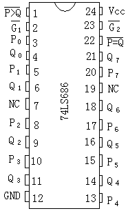
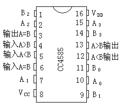
Table 4.13 74LS686 Function Table
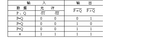
The 174LS686 can perform bit-by-bit comparisons between two 8-bit numbers. As shown in Table 4.13, when the P=Q output is low, the two 8-bit numbers are completely equal; when the P>Q output is low, the P 8-bit number is greater than the Q 8-bit number; and when both outputs are high (i.e., not equal or greater than), the P 8-bit number is less than the Q 8-bit number.
G1 and G2 are control terminals, active low. That is, when G1 = G2 = 0, the comparator operates normally; when G1 = G2 = 1, the comparator does not operate.
The CC4585 in Figure 4.22 (b) is a 4-bit numerical comparator. To expand its logical functionality, a low-order comparison input is designed. The internal structure requires that when comparing only two 4-bit numbers, "input A < B" = 0, "input A = B" = 1, and "input A > B" = 1.
- MOSFET amplifier
- Digital step-kilometer counter
- Cascade amplifier
- Diode and gate circuit schematic diagram and principle analysis
- Analysis of capacitors connected in series
- How to correctly start the transistor
- Introduction to the application of open collector output in high current load control circuit
- Single voltage comparator circuit diagram
- How to understand operational amplifiers in a simple and easy way
- Application of JK flip-flop and T flip-flop
- Reference voltage divider circuit in AD converter
- Delay circuit using operational amplifier
- overload indicator
- Computer temperature controller circuit
- Comparator type undervoltage indication circuit
- Window comparator circuit diagram A
- window comparator circuit
- Position and width adjustable window comparator circuit
- Window comparator circuit diagram 1
- Comparator LED flash circuit


 京公网安备 11010802033920号