Single chip speech recognition circuit
Source: InternetPublisher:太白金星 Keywords: Speech Recognition Updated: 2025/04/18
The new single-chip voice recognition circuit HL7003-02 has a simple circuit structure and few peripheral components. It is very easy to design, manufacture, adjust and operate. It is suitable for enthusiasts to make various voice-controlled amusement machines, home appliance control, smart toys, voice door locks, door bells, etc. It is a single-chip IC that recognizes voice according to the user's own voice input. It can recognize 12 different words and sentences, and can control different output switches to complete the specified functions.
Features:
Built-in microphone amplifier
Built-in A/D converter
12 1.5 second long sentences recognition
Multi-function I/O port
2 normal input pins, 4 trigger input pins
2 output ports, including a 4-output port and an output port
2 LED output drivers
Different encoding methods can be made into dedicated lines
2.4V~3.3V operating voltage
Low power consumption, automatic power off function
Limit parameters
Working voltage (VDD~GND)---------5V
Input voltage changes--------------(GND-0.3V) to (VDD+0.3V)
Continuous working temperature--------------0℃~-+60℃
Electrical parameters
VDD=3V, GND=0V, Ta=+25℃,
Parameters
Test Conditions Min Typ Max Unit
Static current loop 1 10 UA Working current output no-load 2 MA Input low level 0.8 V Input maximum level 2.2 V Output low level output current = -0.5mA 0.5 V Output high level output current = 0.5mA 2.5 V
Functional Description
The operation is divided into two parts. First, the words must be entered, and the second step is to recognize the mode. In addition, during the operation, AP7003-01 can determine whether there is a signal input. All of this is determined by internal programs or specific coding selections.
When you need to do recognition, the target words must be stored in the 12 internal storage areas, which store the characteristics of 12 different words. Each storage area can store words up to 1.5 seconds. You can use the keyboard to select the storage area or use the appropriate command control to enter the words.
You can use an external microphone or other media to input speech or text content. After being accurately amplified by the internal microphone amplifier, the speech signal is digitized by the content A/D converter. The internal sound processor will process the digitized speech and sample the features in the text.
After the target word to be recognized is entered, you can now start the recognition operation and enter the internal word recognition operation mode. The input voice is sampled by the sound processor feature and compared with the sampled features of the target word stored internally. It must be exactly matched with the selected recognized target word. The result is then input to the PA port or other output terminals.
If there is no operation within a certain period of time, the power will be turned off to save power consumption, and can be awakened by pressing a button later.
Pin parameter PIN name Description GNDD Digital ground
LED1 Low level storage LED driver pin, can be designed as a voice input indication, suitable for standard applications
LED2 Low level storage LED driver pin, in the standard application circuit, designed as a sign of voice input verification results
POB1~POB4 output port, used as keyboard scanning, standard application
PIT1~PIT4 Low level valid input port, with internal pull-up resistor, can be designed as an input port or keyboard input Standard application
VDDD Digital power supply VDD
CAPV decoupling capacitor, must be connected between this pin and ground, used for internal voltage reference
OSCI frequency oscillator, control pin, connect a 56K resistor to ground
PIM1~PIM2 common input pin, can be designed as mode control input, used for standard circuit
TEST test pin, used for production test
POSL output mode selection, used for output A port, if ProtA is high effective, then POSL is connected high; if low level is effective, then connect to ground
GNDA analog ground
TREF voice input threshold voltage control
A2OUT output second amplifier
AIIN first (pre-stage) amplifier inverting input
A1OUT pre-stage amplifier output
MICP microphone positive power supply pin
VDDA analog circuit positive power
supply POA1~POA12 output port
PORES high level effective input, clear output port A state
single chip voice recognition circuit HL7003-02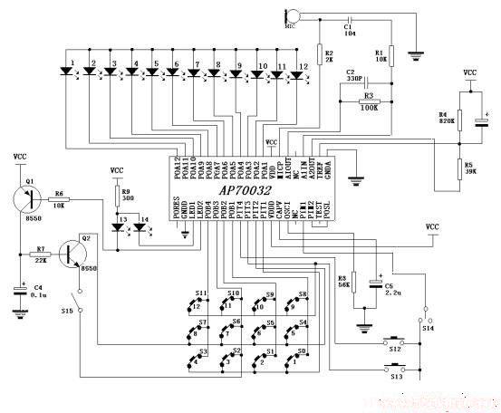
Operation method: 1. After power on, press key ① first, LED1 and POA1 (LED3) light up at the same time, then speak to the microphone immediately (the length of the voice should not exceed 1.5 seconds), POA1 turns off, LED1 lights up, and then "learn" to the microphone, LED2 and POA1 light up at the same time, indicating that the "learning" is successful. Then press key ② again, LED1 and POA2 light up at the same time, and so on, until all keys 1 to 12 are learned. You can also input and learn a key or several keys in a disorderly manner. 2. After learning, you can perform voice recognition operation. The 12-way output can control different electrical appliances (or actions) respectively. The 12-way voice recognition can be operated arbitrarily, that is, shouting a sentence can control the opening or closing of an electrical appliance. The 11th key is the output conversion key, and you need to press this key every time you switch to control an electrical appliance. 3. If you need to clear the "learning" content, you should press the clear key "C". When you input again, you must "learn" again according to the method in step 1. 4. When PIM1 is connected to "1" (high level), it is 12-key mode, and the application circuit is shown in Figure 1. When PIM1 is connected to "0" (low level), it is 8-key mode, and the application circuit is shown in Figure 2. When POSL is connected to "0", POA1~POA12 outputs are low level, and when POSL is connected to "1", POA1~POA12 outputs are high level. Notes: 1. The standard power supply voltage is 3V; 2. The (+) and (-) polarities of the electret microphone MIC must be connected correctly, otherwise the input cannot be made. The MIC is connected to the shell at one end (-) and the other end (+).
- Audio digital-to-analog converter
- Hybrid headphone amplifier
- PCM1794A Audio Digital-to-Analog Converter
- Speaker protection with soft start function
- Modular audio preamplifier
- Single music integrated circuit composed of CW9300
- A simple tone generator circuit
- A circuit for producing extraordinary tones
- Small modified stage speaker crossover
- Delayed soft start circuit of tube amplifier
- Real-time speech recognition system application circuit diagram in home monitoring robot
- Speech recognition circuit HM2006 typical application circuit
- LA4461N audio IC circuit
- TDA2030 audio power amplifier circuit diagram
- Voice controlled bird circuit
- Transistor Audio Mixer Circuit Diagram
- 2-tube FM microphone with 3V power supply
- Simulating bird call circuit schematic diagram
- Several good field effect transistor power amplifier circuit diagrams
- Squelch Tuned Audio Switching/Mixing Circuit Diagram


 京公网安备 11010802033920号