A simple and practical tube amplifier
Source: InternetPublisher:MartinFowler Keywords: Tube Amplifier Circuit Updated: 2024/10/18
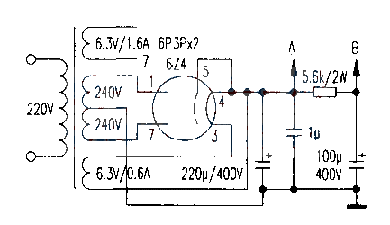
The production materials are a power transformer and two output transformers from the old tube recorder L-601. Considering the carrying capacity of the power transformer and improving the signal-to-noise ratio, the filament voltage of the two 6N3 tubes is rectified by a transformer with a secondary output of 15V and provided after voltage stabilization by 7812 (two filaments are connected in series, the figure is omitted). The circuit diagram only draws one channel, and the non-polarized capacitors in the figure are all CBB 400V withstand voltage capacitors. The resistors without markings are all 0.5W.
After the installation and inspection, power on. The Edifier S2.1 speakers are much more pleasant to listen to than the original amplifier. The treble is delicate and the bass is mellow. It is less harsh and harsh.


- How to adjust the bass and treble of CXA1005
- Making a Simple Tube FM Radio
- LM4766 Dual 40W+40W Power Amplifier
- Using an old tube radio to make a 6N1+6P14 tube amplifier
- 6AS7 tube amplifier
- Dual power supply audio power amplifier circuit composed of LM3875
- LM4903/4905 differential input audio amplifier circuit
- LM4901 audio power amplifier circuit (MSOP package)
- 2W×2 power amplifier circuit using LM1877
- LM4915 is used for dual-channel amplifier circuit
- LA4461N audio IC circuit
- TDA2030 audio power amplifier circuit diagram
- Voice controlled bird circuit
- Transistor Audio Mixer Circuit Diagram
- 2-tube FM microphone with 3V power supply
- Simulating bird call circuit schematic diagram
- Several good field effect transistor power amplifier circuit diagrams
- Squelch Tuned Audio Switching/Mixing Circuit Diagram
- transistor audio mixer
- High quality melody circuit


 京公网安备 11010802033920号