Traditional broadcasting systems generally need to be operated manually at a fixed time, and can only realize one-way broadcasting with few functions. Traditional bell ringing equipment has a single sound source and harsh sound. With the continuous deepening of school teaching reform, these audio-visual teaching equipment can no longer meet the requirements and development of schools. According to the needs of schools, the author uses computer multimedia technology and single-chip microcomputer technology, combined with CATV system to design an intelligent campus broadcasting/examination system. This system can not only realize multi-channel FM broadcasting, but also address broadcasting and control the functional operation of any broadcasting terminal on campus, such as broadcasting switch, sound adjustment and channel switching, etc. At the same time, the broadcasting terminal can also operate its own broadcasting function. It can realize fully automatic timed broadcasting through remote control computers, realizing functions such as bell ringing, class exercises, music during class, and grade language examinations. Therefore, this system is a better choice for the school's modern education "three networks" project.
1 System composition and functions of each part
The composition of the intelligent campus broadcasting/examination system is shown in Figure 1. The system makes full use of the original CATV network to modulate the audio signals of various audio source devices into RF TV signals of different channels through the TV RF modulator, and transmits them to the broadcasting terminal through the same cable as the CATV signal. The broadcasting terminal demodulates the audio signal of the channel to be received through the multimedia electronic tuner, performs power amplification, and drives the speaker to realize broadcasting.

The audio source devices include the remote control computer's sound card, microphone, DVD, cassette player, etc., which are used to output audio source signals. The multi-channel preamplifier amplifies each audio source signal separately to reach the level required by the TV RF modulator audio data. The TV RF modulator modulates the audio source signals output by each audio source device to the carrier frequency of different TV channels. The modulator audio input terminal receives audio phenomena, while the video input terminal is left floating. The entire system is controlled by a remote control computer. The remote control computer sends a control signal through the COM port, which is converted into a 485 format bus signal through an RS-232/RS-485 converter and transmitted to the intelligent controller and broadcast terminal to achieve corresponding control. The intelligent controller decodes the received remote control computer control signal and controls the working status of the audio source device (on, off, play, etc.). The function of the broadcast terminal is to demodulate the audio signal to achieve broadcasting, which can be controlled by the remote control computer and the broadcast terminal respectively.
2 Hardware Design and Implementation
2.1 Intelligent Controller
The function of the intelligent controller is to convert the received remote control computer instructions into corresponding infrared remote control signals. The infrared remote control signal has a self-learning function and is used to control the working state of the sound source equipment. The composition of the intelligent controller is shown in Figure 2. The main control is based on the single-chip microcomputer TA89C52. The infrared remote control signal is composed of a string of coded pulses modulated by a carrier frequency of 38-40KHz. The self-learning function of the infrared remote control signal is achieved by measuring the high-level width and low-level width of the demodulated coded pulse, and writing the width data into the memory in pulse order. The restoration of the infrared remote control signal only needs to remove the learned stored data from the memory, generate the original coded pulse string, and modulate it into an infrared signal.
When the infrared remote control signal is self-learning, the infrared receiver (SFH506-38) is responsible for demodulating the infrared remote control signal to be learned. The demodulated remote control coded pulse string is directly sent to the INTO and TO pins of AT89C52. The single-chip microcomputer AT89C52 measures the high and low level widths of each pulse. The E2PROM chip AT24C64 with an I2C bus interface is used as a memory to save the high and low level width data of the remote control coded pulse string. Each function infrared remote control signal occupies a corresponding space in the E2PROM. AT89C52 receives the broadcast control computer command through MAX3082, decodes it into the corresponding remote control coded pulse signal and outputs it from P1.1, and performs "OR" modulation with the 38KHz carrier signal output by P1.0 to complete the modulation. After being driven by 9013, the infrared light emitting diode sends out the infrared remote control signal to control the working status of the sound source equipment. [page]
2.2 Broadcast Terminal
The hardware schematic diagram of the broadcast terminal is shown in Figure 3. The control core is the AT89C51 single-chip microcomputer and the multimedia electronic tuner TCL2002MB-2 is the broadcast reception demodulation module. The broadcast terminal consists of broadcast reception adjustment, sound control, power amplifier, buttons, display, storage, bus driver and other modules. Broadcast reception demodulation, sound control and data storage all use the I2C bus control mode. P1.7 of the single-chip microcomputer is defined as SDA and P1.6 is defined as SCL.
2.2.1 Broadcast reception and demodulation module
TCL2002MB-2 is designed by TCL for RF applications in computer multimedia environments. It is small in size, compact in structure, and stable in performance. It can directly demodulate video and audio signals with a peak value of 1V from RF signals. The demodulated RF effect covers all TV channels. Tuning and band switching are completed by converting to a digital phase-locked loop system. The control information is written by the I2C bus. Only the audio output of the tuner is used in the broadcast terminal, while the video output is not used.
The I2C write mode of TCL2002MB-2 is shown in Table 1, and the I2C write control mode logic is shown in Table 2, where the values of MA1 and MAO are determined by the tuner AS pin voltage. Usually, the AS pin is grounded, and MA1MAO is 00 at this time; CP is used to set the tuning speed, usually CP=0, and the tuning is medium speed; T2T1T0 is set to 001; RSARSB is the tuning step setting, usually set to 11, the tuning step is 62.5KHz, and it can correctly tune to the required channel; UHF, VH, VL are band switches, 1 is off, 0 is on, N14-70 is the programmed division ratio, which can be calculated by the formula, fRF (pc) is the image carrier frequency of the channel to be received, in MHz.
The programmed frequency division ratio of each channel is burned and fixed in the MCU ROM together with the program. When selecting a channel to listen to, the MCU takes out the programmed frequency division ratio of the desired channel through the difference table, writes it into the tuner in the I2C write mode specified in Table 1, tunes, and demodulates the audio signal. Reference [1] proposes a virtual I2C bus software package designed in platform mode and suitable for 80C51 series microcontrollers. The data read and write subroutines of the I2C bus software package can be directly called according to the specified read and write mode to implement operations on the tuner and other I2C bus devices.
2.2.2 Digital volume, tone control and power amplifier module
In order to realize the control of the volume and tone of the broadcast terminal by the broadcast control computer and the broadcast terminal, the system uses PHILIPS's TDA 7315 two-channel digital audio processor. TDA7315 can realize volume, tone, and channel balance control. All control information is written by the CPU through the I2C bus.
The write mode of TDA7315 is shown in Table 3, and the logic table of I2C write control mode is shown in Table 4, where A2A1A0 is 000, the volume is attenuated to 0dB, and when it increases from 000 to 111, the volume is attenuated in 1.25dB steps; B2B1B0 is 000, the volume is attenuated to 0dB, and when it increases from 000 to 111, the volume is attenuated in 10dB steps; L is 0 when the volume is turned on, and is muted when it is 1; C3C2C1C0 is 0111, the tone is attenuated to 0dB, and when it decreases from 0111 to 0000, the tone is attenuated in 2dB steps, and when it increases from 0111 to 1111, the tone is increased in 2dB steps.
When adjusting the volume and tone, the microcontroller reads the current value from the E2PROM, performs increase and decrease operations, and then writes the operation results to the TDA7315 in the write mode specified in Table 3 to achieve corresponding control.
The power amplifier module adopts TDA2030, and the output power of each channel can reach 12W, which can meet the requirements of most broadcast terminals.
2.2.3 Bus drive, display, grounding and address setting
The broadcast terminal and the broadcast control computer communicate using the RS-485 specification. The AT89C51 is connected to the RS-485 bus through the serial port. The bus driver uses MAX3082, which can connect 256 terminals and meet the requirements of most schools.
The 2-digit LED digital tube shown in Figure 3 can display the listening channel, volume, tone and other conditions. The default display is the current listening channel. When the sound operation is selected, the current volume and tone conditions can be displayed. The display circuit adopts static scanning mode. CD4513 is a BCD-7-segment latch/decode driver. P1.0, P1.1, P1.2, and P1.3 output the BCD code of the displayed number, and P1.4 and P1.5 generate bit input latch signals.
The "STATUS" button on the broadcast terminal panel realizes the volume, tone, and channel function conversion, and the "UP" and "DOWN" buttons realize the volume, tone, and channel increase and decrease. The microcontroller makes corresponding function changes by judging the number of low levels of P2.2, and changes the volume, tone, and channel by judging the low levels of P2.1 and P2.0, and writes the set value into the memory of the I2C bus E2PROM (AT24C02). [page]
Each broadcast terminal is connected in series on the RS-485 bus. The broadcast control host communicates with each broadcast terminal through multi-machine communication. Each broadcast terminal has its own address. The microcontroller sets the terminal address by reading the DIP switch status.
3 Software Design
3.1 Broadcast control host software
The software of the broadcast control computer is mainly composed of an automatic playback module and a control module. The automatic playback module includes a playback library and a timed playback module. The playback library can store a large number of sound source files in the MP3 format. New MP3 format sound files can be continuously added and classified through database technology; the MP3 player is embedded in the timed playback module. The timed playback module can set the playback time and play specific songs, or set to play a certain type of songs, start the sound card to play ringtones, physical exercises and break music at regular intervals, etc.; the control module completes the sending of commands, including commands to broadcast terminals and broadcast equipment. The entire software adopts object-oriented programming methods and uses the visual programming tool DELPHI. The computer communicates with other devices using the control MSCOMM, and the database uses the SYBASE system.
3.2 Intelligent Controller Software
The core of the intelligent control software is the infrared remote control signal self-learning module and the infrared remote control signal transmitting module, and its program flowchart is shown in Figure 4.
During the self-learning of infrared remote control signals, timers T0 and T1 are defined as working mode 1, the GATE bit of T0 is set, and the INT0 external terminal mode is set to edge trigger. When there is no infrared signal, the infrared receiver outputs a high level. When there is an infrared signal, the pulse string output by the infrared receiver jumps from a high level to a low level, causing the INT0 external interrupt. Each time the INTO external interrupt occurs, the timing is stopped first, and the count values of T0 and T1 are recorded (the count value of T0 is the high level width of the pulse, and the low level width is the count value of T1 minus the count value of T0), then the count values of T0 and T1 are cleared, and the timing is restarted. At the same time, the high level and low level width data are written into AT24C64 for storage, and the widths of each high level and low level of the remote control coded pulse string are measured one by one, and stored in E2PROM in order.

When the infrared remote control signal is transmitted, T0 is set to working mode 1, and the table is looked up according to the instructions. The learned and stored high and low level width data are taken out from E2PROM in turn, and the initial count value is assigned to timer T0 and started. The initial count value is the inverse of the measured value. Through the T0 interrupt, the infrared remote control coded pulse string is restored at P1.1.
3.3 Broadcast Terminal Software
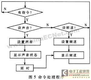
After the broadcast terminal is powered on and reset, it enters a state of waiting to receive control commands. The command processing program flowchart is shown in Figure 5.
This system has obtained a national patent and has been widely used in various schools in Guangdong and Guangxi. Because the system is fully functional, easy to operate and has good results, it is very popular among the schools that use it.
Previous article:Design and implementation of remote automatic alarm system
Next article:Multi-point temperature measurement system based on thermistor
Recommended ReadingLatest update time:2026-03-25 16:49

- Popular Resources
- Popular amplifiers
 Circle teaches you how to play USB third edition supporting program
 Ray tracing system design (schematic diagram, source code, etc.)
 Linux Command Line and Shell Script Programming Handbook
- Microchip introduces the SAM9X75, a hybrid microcontroller in an automotive-grade system-in-package (SiP) architecture.
- From Control to System: TI Reshapes the Boundaries of Embedded MCUs with Edge AI
- UWB653 Module User White Paper: Simplifying UWB Ranging, Positioning, and Communication
- The Xunwei RK series development board SDK kernel version has been upgraded from 5.10 to 6.1 LTS.
- Comparison of LoRa, LoRaWAN, NB-IoT and 4G DTU technologies and analysis of industrial wireless solution selection.
- How AI is reshaping the boundaries of the convergence of the Internet and the Internet of Things
- The MCX A microcontroller family welcomes innovation with the launch of six new product series.
- Infineon continues to solidify its global leadership position in the microcontroller market.
- Functions and Applications of PLC IoT Gateways in Smart Factories
 Professor at Beihang University, dedicated to promoting microcontrollers and embedded systems for over 20 years.


- Developing USB peripherals with MC68HC05JB4
- Design and implementation of remote automatic alarm system
- Design of CATV-based intelligent campus broadcasting/examination system
- 9 simple digital filtering algorithms (C language source program)
- Optimization of C language program structure in single chip microcomputer system
- Design of UHF handheld reader based on AS3990 chip
- PIC18F46J50: 8-bit wireless development solution [Image]
- Design and Implementation of Spectrum Analysis System Based on LabWindows/CVI
- Homemade healthy and energy-saving water dispenser
- The Future of Power Supply Design for Portable Applications
- XMOS showcases several innovative technologies at Embedded World 2026
- U-tec: Native Matter-over-Thread support, breaking down ecosystem barriers.
- Kwikset: Seamless Wi-Fi unlocking experience with ultra-low power consumption
- Xthings: Z-Wave long-range technology empowers AIoT smart locks
- Silicon Labs is driving and reshaping the smart lock industry landscape.
- Silicon Labs is driving and reshaping the smart lock industry landscape.
- Xthings: Z-Wave long-range technology empowers AIoT smart locks
- Kwikset: Seamless Wi-Fi unlocking experience with ultra-low power consumption
- U-tec: Native Matter-over-Thread support, breaking down ecosystem barriers.
- Durin: Leveraging the Aliro standard to create a seamless mobile entry experience
- How does the wdm driver support asynchronous IO?
- How to input Arabic, Portuguese, Spanish and other foreign languages in EVC?
- TI Wireless Products RF Hardware FAQ - 13 new webinar Q/A summaries
- A case of project delay caused by insufficient current drive
- Beaglebone Black uses Ubuntu to surf the Internet
- Quectel BC28 NB module cannot read SIM card
- UHF RFID reader circuit design
- FPGA Handouts
- I found a circuit on the Internet that uses cyclone ii as the main control. Please take a look.
- [FPGA Open Source Tutorial Series] Chapter 8 Independent Key Debounce Experiment A


 京公网安备 11010802033920号