1. Introduction
RFID (radio frequency identification) is a non-contact automatic identification technology that emerged in the 1990s. It uses the characteristics of radio frequency signal propagation in space to achieve contactless information transmission through spatial coupling (alternating magnetic field or electromagnetic field), and realizes automatic identification of the identified object through the transmitted information. The identification process does not require physical contact, and the writing and reading of tag information can be completed without manual management. Using RFID technology, multiple targets and moving targets can be identified at one time. In addition, electronic tags are readable and writable, can store a large amount of information, have strong security and confidentiality, are not afraid of external dust, stains, etc., and have strong environmental adaptability. It is precisely because of these advantages that other identification methods do not have that RFID technology has a wide range of applications and great development prospects in logistics, transportation, traffic, production, anti-counterfeiting and other fields.
This paper designs a UHF RFID handheld reader/writer with MSP430f149 chip as the controller based on AS3990 chip. It can complete all reading, writing and control operations for electronic tags that comply with EPCGen2 standard. Its mobile intelligent management function is mainly used in logistics, supply chain, warehouse and other occasions.
2. System Overview and Design Principles
In the wireless radio frequency identification system, the RFID reader is a key device used to identify the tag and send the collected data information to the background for processing. It plays a key role in ensuring the correctness and reliability of the RFID system. At the same time, the RFID reader can also write to the tag and store the information in the tag. The design of the reader is completely based on the ISO/IEC18000-6C standard protocol.
2.1 Introduction to ISO/IEC18000-6C Protocol
The ISO/IEC18000-6C protocol stipulates that when data is transmitted, the high byte is transmitted first, and the modulation mode of the forward link is ASK, and PIE encoding is used. The anti-collision algorithm is based on probability and slotting algorithm; the backward link uses backscatter modulation technology to achieve data transmission, and Miller encoding or FM0 encoding can be selected. The 6C standard uses a relatively simple encryption algorithm to prevent the spread of sensitive data in the process of the reader obtaining tag information. This algorithm only encrypts information when the reader transmits data to the tag, and the data information transmitted from the tag to the reader is not encrypted. The implementation process is that the reader obtains a 16-bit wide random number from the tag and performs modulo 2 and calculation with the 16-bit wide data to be transmitted to obtain the ciphertext, and then the tag decrypts to obtain the original data sent by the reader.
2.2 Anti-collision mechanism
There is a 16-bit random number generator in the tag to solve the anti-collision algorithm problem. The query command contains the slot counter parameter Q. After receiving the query command, the participating tags should select a random value in the range of (0, 2 Q -1) and load the selected value into their counters. Tags with a selected value of zero will switch to the response state and respond immediately. Tags with a non-zero selected value should switch to the arbitration state and wait for the query adjustment or query command to be issued.
The interrogator uses three basic operations to manage tag groups, namely selection, inventory, and access. Each operation consists of one or more commands. The definitions of the three basic operations are as follows:
(1) Selection: The process by which an interrogator selects a group of tags for inventory and access. An interrogator can use one or more selection commands to select a specific group of tags before an inventory is taken.
(2) Inventory: The process of the interrogator identifying the tag. The interrogator transmits a query command in one of the four calls to start an inventory cycle. One or more tags can respond. The interrogator checks the response of a tag and requests the tag to send PC, EPC and CRC-16.
(3) Access: The process of the interrogator transacting with each tag, i.e. reading or writing tags. Tags must be identified before access, and access consists of multiple commands. If multiple tags respond, the card reader can resolve the 16-bit key sent by one of the tags by detecting and resolving waveform conflicts. Other unresolved tags will receive the wrong 16-bit key and return to the arbitration state. After issuing a query command, an inventory cycle will be started, and the interrogator will issue one or more query adjustment or repeat query commands. The query adjustment command simply repeats the previous query command, which can increase or decrease the value of Q, but will not introduce new tags into the inventory cycle. The repeat query command repeats the previous query command, but the parameters remain unchanged, and new tags will not be introduced into the inventory cycle. After receiving the query adjustment command, the tag in the arbitration or response state first adjusts Q, then selects a random value in the range of (0,2 Q-1) and loads the value into the slot counter. The tag with a selected value of zero should switch to the response state and respond immediately; the tag with a selected value of non-zero should switch to the arbitration state and wait for the next command. [page]
3. System hardware design
3.1 Introduction to main chips
MSP430 uses the currently popular Reduced Instruction Set (RISC) structure. One clock cycle can execute one instruction, so that when the MSP430 works at an 8MHz crystal oscillator, the instruction speed can reach 8MIPS. It has up to 64KB addressing space including ROM, RAM, flash RAM and peripheral modules. The MSP430 series of microcontrollers combines TI's high-performance analog technology, and each Chengdu integrates a rich set of on-chip peripherals. Depending on the model, the following functional modules may be combined: watchdog, analog comparator A, timer A, timer B, serial port 0, 1, hardware multiplier, LCD driver, 10-bit and higher precision ADC, DAC, etc. Compared with other microcontrollers, the MSP430 series of microcontrollers can greatly extend the battery life, and have ESD protection and strong anti-interference ability.
The AS3990HUF reader chip is a 900M reader system with an integrated analog front end and exchange protocol system. It complies with the ISO18000-6C (EPCGen2 is specifically used for logistics management) standard. It has low-voltage transmission code, low-voltage decoder, CRC code verification, selectable clock output, voltage output within 20mA for external devices, provides voltage for the RF output stage, has ASK (keying) and PR-ASK modulation (where ASK is adjustable modulation), supports frequency hopping, power off, standby and working modes, and can also be powered by USB.
3.2 Hardware Design
3.2.1 RF module design: The RF module uses AS3990HUF as the core chip, and an external power amplifier is used to ensure that its power meets the necessary conditions for long-distance reading and writing transmission. The RF part is the front end of the reader/writer. When the control circuit sends a transceiver instruction, the RF circuit will complete the carrier modulation of the instruction and send the carrier to the RF tag, as well as demodulate the returned received signal and transmit the processed baseband signal to the control circuit.
3.2.2 Digital module design: The digital part is designed with the MSP430 series microcontroller as the core chip. The main functions of the digital part include realizing the waveform encoding of the command sent to the tag, decoding of the return signal, read and write command flow control, error control, sending control commands and receiving data, realizing the interface protocol between the host computer application, collecting and processing input and output signals, realizing the relevant algorithms of the reader function, controlling the working mode of the RF circuit, etc. (including the control of output power, tag reading mode, carrier frequency, etc.)
3.2.3 Antenna design: The antenna used in the design is mainly to radiate electromagnetic waves and receive electromagnetic wave signals returned from the tag. By adopting the circularly polarized microstrip antenna solution, a gain of 3db can be achieved, and the size is 80mm*80mm*6mm.
4. System software design
4.1 Driver Software Design
The hardware driver software is written in C language, mainly using modular programming ideas. The system main program is a complete RFID reader system, which is used to control the working status and working mode of each module of the hardware circuit and coordinate the work of the entire reader reading and writing process. The main program of this reader hardware driver can be mainly divided into the following parts: serial communication program, tag reading and writing program, anti-collision program, data processing program, etc. Figure 2 is the main program flow chart for reading and writing electronic tags:
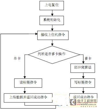
pictext"> Figure 2 Flowchart of the main program for reading and writing electronic tags
4.2 Application Software Design
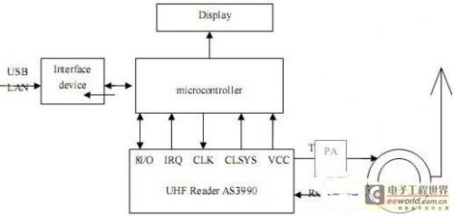
The application software is located on the host computer and runs on the Windows operating system. Therefore, C++ programming language is used to implement the reading and writing of data in the electronic tag, reading user data, storing user data, encrypting and decrypting tags and "unchangeable" operations, setting the reader working mode, etc. Figure 3 is a block diagram of the software system: [page]

Figure 3 System software block diagram
5. Conclusion
The RFID UHF handheld reader designed in this paper fully combines the advantages of software and hardware, and can realize the reading and writing operations of EPCGEN2 electronic tags. Using the antenna designed in this paper, the reading distance of the tag can reach 1.4m, and the writing distance of the tag can reach 1m. It has good anti-collision performance when multiple tags are used, and can read 20 electronic tags at the same time. The reader can be connected to the host computer through the serial port and transmit data. The reader has the advantages of low cost, high sensitivity, stable communication, reliable information, and simple operation. It has a broad application prospect in various industries and is also of great significance to the promotion of RFID.
Previous article:Design of a heat meter based on ultra-low power microprocessor MSP430
Next article:Analysis of the significance of using M430/OS on the MSP430 MCU
Recommended ReadingLatest update time:2026-03-25 16:39

 MSP430F149 examples and programs
 msp430f149 learning board.rar
 Design and implementation of wireless voice transmission system based on M-Power500
- Microchip introduces the SAM9X75, a hybrid microcontroller in an automotive-grade system-in-package (SiP) architecture.
- From Control to System: TI Reshapes the Boundaries of Embedded MCUs with Edge AI
- UWB653 Module User White Paper: Simplifying UWB Ranging, Positioning, and Communication
- The Xunwei RK series development board SDK kernel version has been upgraded from 5.10 to 6.1 LTS.
- Comparison of LoRa, LoRaWAN, NB-IoT and 4G DTU technologies and analysis of industrial wireless solution selection.
- How AI is reshaping the boundaries of the convergence of the Internet and the Internet of Things
- The MCX A microcontroller family welcomes innovation with the launch of six new product series.
- Infineon continues to solidify its global leadership position in the microcontroller market.
- Functions and Applications of PLC IoT Gateways in Smart Factories
 Professor at Beihang University, dedicated to promoting microcontrollers and embedded systems for over 20 years.


- Developing USB peripherals with MC68HC05JB4
- Design and implementation of remote automatic alarm system
- Design of CATV-based intelligent campus broadcasting/examination system
- 9 simple digital filtering algorithms (C language source program)
- Optimization of C language program structure in single chip microcomputer system
- Design of UHF handheld reader based on AS3990 chip
- PIC18F46J50: 8-bit wireless development solution [Image]
- Design and Implementation of Spectrum Analysis System Based on LabWindows/CVI
- Homemade healthy and energy-saving water dispenser
- The Future of Power Supply Design for Portable Applications
- XMOS showcases several innovative technologies at Embedded World 2026
- U-tec: Native Matter-over-Thread support, breaking down ecosystem barriers.
- Kwikset: Seamless Wi-Fi unlocking experience with ultra-low power consumption
- Xthings: Z-Wave long-range technology empowers AIoT smart locks
- Silicon Labs is driving and reshaping the smart lock industry landscape.
- Silicon Labs is driving and reshaping the smart lock industry landscape.
- Xthings: Z-Wave long-range technology empowers AIoT smart locks
- Kwikset: Seamless Wi-Fi unlocking experience with ultra-low power consumption
- U-tec: Native Matter-over-Thread support, breaking down ecosystem barriers.
- Durin: Leveraging the Aliro standard to create a seamless mobile entry experience
- R7F0C80212 development board program download
- DSP2812 CMD detailed configuration example
- Homemade LED lamp test data
- Hardware Engineer's Manual_Full
- Basic principles of hardware development
- 66分求WDMWIZ.AWX這個文件 (Programming the Microsoft Windows driver model一書中的)
- [DIY] Make a new QS18-12 glow clock case for her classic style with a gorgeous coat
- 【ESP32-Korvo Review】 01 Unboxing Experience
- Chat source code under WinCE
- Newcomer report~


 京公网安备 11010802033920号