
USB voltmeter
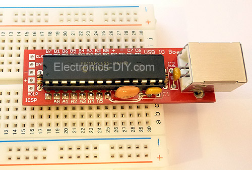
The USB voltmeter is a PC-based, dual-channel voltmeter built around the PIC18F2455/PIC18F2550 microcontroller. It measures voltages from 0.00V to 500.00V with a resolution of 10mV. The USB voltmeter sends measurement data to a PC via a standard USB connection, where it is displayed on a computer monitor. It is self-powered, drawing very little current from the USB port. Voltage readings are displayed using the included USB voltmeter software.
USB voltmeter specifications
Voltage input range: 0 - 500V
Voltage input channels: 2
Voltage resolution: 10mV
Power supply: 5V (USB powered)
PCB dimensions: 18mm x 59mm / 0.7 inches x 2.3 inches
USB Voltmeter Component List
Programmed PIC18F2550 microcontroller
USB voltage meter PCB
12-pin gold-plated connector
8-pin gold-plated connector
28-pin IC socket
USB Type B connector
20MHz crystal resonator
C1 - 470nF capacitor (474)
C2 - 100nF capacitor (104)
C3 - 10uF / 35V capacitor
R1, R2 - 10K micro resistors (brown, black, orange, gold)
R3, R4 - 100K 1% resistors (brown, orange, black, black, brown)
R5, R6 - 6.8K 1% resistors (blue-gray, black-brown) - for measuring voltages up to 70V.
R5, R6 - 1K 1% resistors (brown-black) - for measuring voltages up to 500V 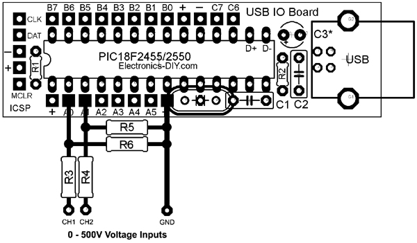 with USB voltmeter driver installed.
1) Download and extract the USB voltmeter driver.
2) Connect the USB voltage meter to the computer using a standard USB cable.
3) Windows will prompt you to install the driver. Point to the extracted driver file.
Windows 2000 / XP
In Windows 2000 or XP, you will be prompted twice to install two drivers. On the first prompt, navigate to the MCHPUSB driver folder. On the second prompt, navigate to the USB CDC driver folder.
Windows 7 / Vista
In Windows 7 or Vista, if the MCHPUSB driver is already installed, you may only be prompted to install the USB CDC driver once.
USB voltmeter software
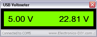
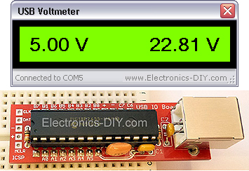
After installing the USB driver, launch the USB voltmeter software. Once the USB voltmeter board is plugged in, the software will automatically establish a connection to the COM port in the background and display voltage readings from both input channels.
USB voltmeter software calibration
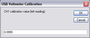
For maximum accuracy, the readings of both input channels can be calibrated using voltmeter software. Pressing the 'ESC' key in the software will bring up a similar window for each channel.
If measuring voltages up to 500V, install 1K resistors for R5 and R6. The default calibration value for a 1K resistor is 0.67.
If measuring voltages up to 70V, it is recommended to install 6.8K resistors for R5 and R6. This will provide greater stability and voltage resolution in decimal values. The default calibration value for a 6.8K resistor is 0.0999.
After entering the calibration value, press Enter or click the OK button to save the settings.
For maximum accuracy, the calibration value can be slightly increased or decreased. Simply connect a known voltage to the input and match the voltage of the USB voltmeter to that of a commercial voltmeter.
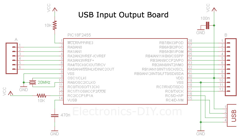
USB voltage meter board schematic diagram
USB Voltmeter Kit
- 9V Battery Voltage Monitor
- Simple Digital Oscilloscope
- Equivalent Series Resistance and Low Resistance Tester
- Extending Current Measurement Range with Resistor-Free Sensing Solutions
- How to Accurately Measure Current and Voltage in GSM Systems
- Design and production of logic detectors
- DIY Stress Measurement Table
- Coil short circuit tester
- Lossful and lossless current test methods
- Test circuit composed of TDA6106Q with feedback factor 1/116
- Three-phase alternating current detection circuit
- Bus door status detection circuit
- Object presence and displacement detection circuit
- Downhole oxygen concentration detection circuit
- Woodworking hand planer safety device detection circuit
- Long-distance ringtone detection circuit using photoelectric coupler
- Detect the major point waveforms of the circuit
- Long wave infrared detection circuit
- Cordless telephone ring current detection circuit
- Optical fiber vibration measurement detection circuit


 京公网安备 11010802033920号