Video Production: [(Open Source) Touch-Sensitive Illuminated Table Upgrade, River Table - Bilibili] https://b23.tv/kPmtszI
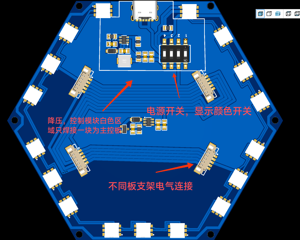
1. Only the first motherboard in the white area needs soldering; the others don't
. 2. Switch 1 is the power switch, switch 2 is the blue light switch, switch 3 is the red light switch, and switch 4 is the green light switch. The three colors can be combined.
3. The PCB needs to be tapped manually to M3 (also needed for 3D printed parts).
4. There are two 3D model files: one for the main control board and one for other luminous modules.
5. The PCB and model are fixed with M3X5 headless hex screws. Modules are fixed together with M3X10 studs and hex nuts.
6. Electrical connections between different modules are made with 1.25mm pitch, 15cm long 5-pin connectors.
7. The PCB and model must be oriented in the same direction, the charging port and the model notch must be aligned, and all module charging ports should face the same direction when fixing.
8. The attachments include some purchase links and 3D printing files (25% infill for 3D printing).
9. The delayed shutdown and light adjustment functions have been completed, but there is still one problem to be solved: the output power of the step-down module is only 2W, which means that the more lights are touched,
the lower the brightness of the lights (there is no solution yet), and increasing the voltage or current will not increase the power.
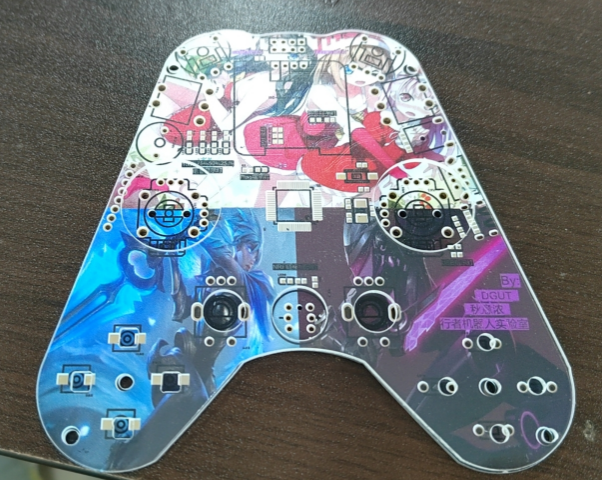
As an RC player, to allow my "dear teammates" to use cool, compatible, and multi-channel remote controls instead of those from Xbox, PS2, or even Focal, which use different protocols, I designed a multi-channel smart RC remote control based on color silkscreen printing. This is also my second color silkscreen printing board ☺
Project Introduction:
As an Rcer member and fellow embedded hardware engineer, designing a remote control that is feature-rich, has a smooth feel, operates seamlessly, and is even presentable is the minimum requirement. Based on the project's requirements, this Vol. 1.0 version of the Rc remote control was designed.
Vol. 2.0 and Vol. 3 versions will feature a redesigned exterior and utilize the Rtos operating system and state machine programming to debug the peripheral transmitter demo. The receiver will be open-sourced after the 23RC competition (attached is an unflattering picture of version 2.0).

—P.S.: The software and hardware for this project were 100% debugged by myself. However, due to my software skills being far inferior to those of the embedded software team members, after debugging the hardware and writing the bare-metal demo code for all peripherals, it was handed over to the embedded software team members for onboard debugging.

Project Analysis:
This remote control is a multi-functional remote control based on the STM32F4 platform.
Configuration:
(I) Main Controller: Uses an STM32F405RGT6 main controller with a main frequency of 168MHz, 1MB FLASH storage, and 192KB SRAM. This controller was chosen because it is based on the high-performance Arm Cortex-M4, has a high frequency, and supports up-to-date system latency and protocol layer speeds on RTOS systems. It also supports FPU floating-point unit calculations, making the calculation of joystick error filtering algorithms very convenient. Furthermore, the sufficiently large RAM provides good support for multi-threaded, multi-state processing programming and DMA memory buffer allocation.
(II) Communication: Dual communication modules are used, utilizing NRF24L01+Lora (Lora was deleted after a minor bug was found during debugging of the previous board, so only single communication is used). A high-power 500mW high-performance PA+LNA module is selected for 2.4G wireless communication. This module has significant advantages over the low-power version of the same module. After actual testing, its communication quality through walls is significantly improved, and the air speed is adjustable. Currently, the maximum communication distance can reach 1Km.
(III) Display: 0.96-inch 4PIN I2C OLED display screen. The IO port usage is small, reducing resource consumption. At the same time, a UI interface based on u8g2 has been designed, and the relevant API functions are encapsulated for user calls. For UI design, the mainstream are currently LVGL and U8g2. LVGL is more commonly used in LCDs, while u8g2 has less memory usage and is very friendly to small-screen OLEDs. At the same time, the functions in the library are simple to operate and easy to call.
(IV) Channels: 28 physical channels, including 18 analog channels and 10 switch channels, comprising: 4 joystick channels, 4 two-stage toggle switch channels, 2 three-stage toggle switch channels, 2 potentiometer knob channels, 4 button channels, and 2 switch reset channels.
(V) Menus: Up, Down, Left, Right, Add, Subtract, Confirm, Exit (8 menu buttons are planned to be supported). The buttons will be programmed using a state machine algorithm—the classic Switch-case method. Combined with U8g2, it will implement a multi-level menu with progressively advancing pointer switching, currently achieving up to three levels. It efficiently debouncing buttons, and the advantage of using state machine programming for switching between long and short presses is that it allows for layer-by-layer state transitions.
(vi) Peripherals: An external USB-to-serial communication matrix keyboard module is added for dual-MCU dual-machine communication. It controls 16 keys through 8 I/O ports and implements hardware debouncing + software debouncing. This matrix keyboard module was a pre-implemented function in the previous demo and has been deleted from this board. Only the classic MPU6050 IMU & gyroscope has been added to realize motion-sensing remote control operation, which is controlled by changing the posture of holding the remote control.
(vii) Power supply: It is powered by a 2S lithium battery and has a built-in 5V1A charging management circuit. It also supports the Power_Charge switching circuit and supports Type-C power supply and lithium battery power supply. The charging and discharging modes can be switched through Charge. It has built-in reverse connection protection to prevent board explosion caused by the Xh2.54 positive and negative male connector.
(VIII) Control: The MCU's internal 12-bit high-precision ADC is used to sample the voltage of the dual model joysticks. There is one throttle joystick and one directional joystick. For the global coordinate system X and Y, simple hardware filtering is applied. For software processing, the measured linear curve of the voltage value in the 0-3V range shows a deviation of approximately 200mV within every 50-100 data points. The filtering algorithm used is the mean filtering algorithm, which is simple and provides smooth operation of the steering wheel chassis even after processing to one decimal place.
(IX) Warning: A BJT switching circuit is used to control the passive buzzer, providing low voltage, danger warnings, and low battery warnings. A pre-installed power-on beep function is also included to indicate that all peripherals have been fully reset and are ready for operation.
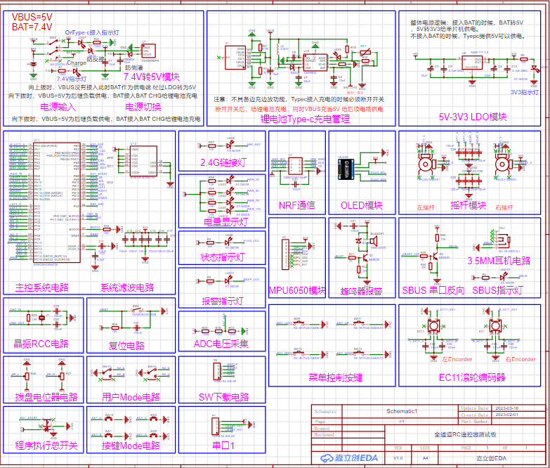
(X) Monitoring: Includes a four-channel LED driver circuit. The lithium battery voltage is collected via a three-resistor lithium battery voltage acquisition circuit to achieve power monitoring. Four LEDs display four levels of power level, and the current battery level and corresponding monitoring indicators can be displayed through a UI interface. Figure ①: Mind Map Schematic Design Description
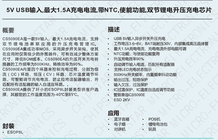
of RC Remote Control Based on STM32F405RGT6 PS: This schematic is for reference only. The circuit design of each module will not be emphasized; it is relatively simple. Various peripherals are mainly for software demo writing. This schematic description mainly emphasizes the circuit design and precautions for the Power & PowerCharge circuits. ①Power & Charge & USB ① This is the power input and power switching section. When flipped up, Vbus is not connected. At this time, Vbat acts as the power supply terminal, supplying power to the load through a low-dropout LDO. When flipped down, BAT is disconnected, and BAT is connected to BAT_CHG as the Charge pin, acting as the 2S lithium battery charging pin. Flipping down allows connection to Type-C, which acts as the power supply terminal and can also power the overall circuit and charge the lithium battery. ② The lack of simultaneous charging and discharging means it does not support charging the lithium battery while simultaneously discharging it. However, it supports power supply via Type-C when connected, thus achieving simultaneous charging and discharging in another way. When charging via Type-C, the lithium battery's charge circuit must be disconnected, i.e., the switch must be flipped down. Power is then supplied to the BAT pin of the CS5090E. The CS5090E datasheet will be analyzed below. ③ The 6-pin Type-C uses a switch to switch between lithium battery mode and charging mode. The main charging management IC, CS5090E, performs balanced charging for the 2S lithium battery. Its main features are described below using its datasheet. This is a domestically produced dual-cell lithium battery boost charging IC that supports Vin=5V, a maximum charging current of 1.5A, integrates a high-power switching MOSFET for reduced power consumption and high conversion efficiency, has a switching frequency of 500kHz, and incorporates four loops to control the charging process: a constant current (CC) loop, a constant voltage (CV) loop, and a temperature regulation loop. It supports LED charging status indication and includes circuit protection functions: output overvoltage protection, short circuit protection, and input undervoltage protection. The IC integrates PESD protection and can withstand 2KV high-voltage breakdown. ④ Pin Definitions ⑤ Typical Circuit Application Diagram Note: The selection of external passive components should be based on the actual application requirements .


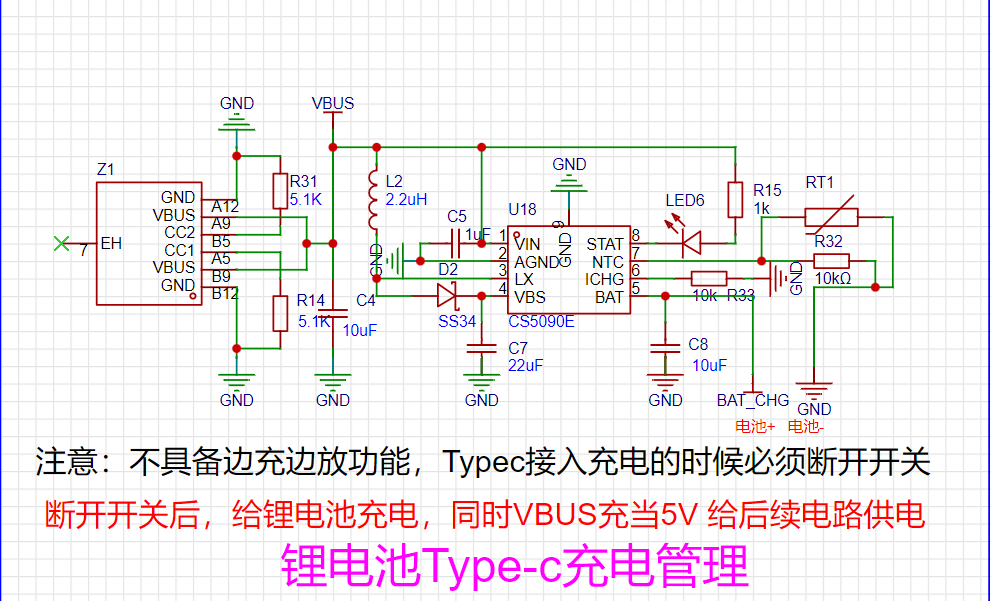


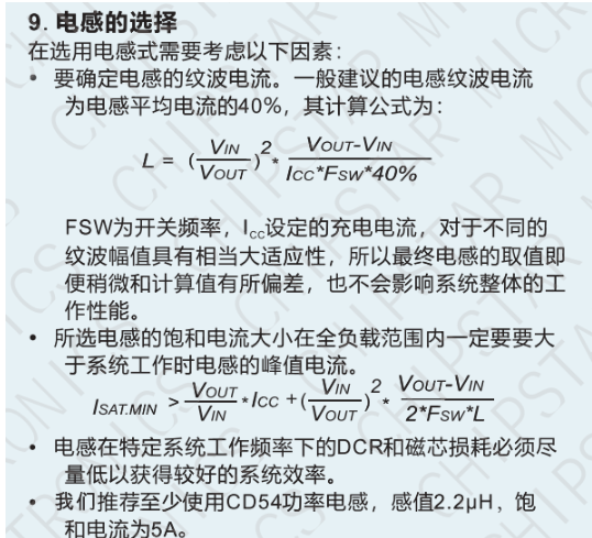
⑥ For example, if the inductor ripple current needs to be controlled within 40% of the average inductor current, the saturation current of the selected inductor must be calculated according to the formula in its datasheet. This saturation current must be greater than the peak inductor current during system operation within the output load range to ensure low DCR and low signal loss at the characteristic operating frequency, thus guaranteeing system efficiency.

⑦ For example, the charging management IC itself supports NTC thermistor over-temperature protection. The battery temperature is detected through the NTC pin. The protection mechanism works as follows: after connecting the NTC to GND via an external resistor, the NTC_Pin outputs a fixed 20uA current. The voltage drop generated by this current determines the battery temperature range. In its internal temperature-voltage fitting linear curve, the internal low temperature judgment point is 1.43V, and the internal high temperature judgment point is 0.38V. If the NTC function is not needed, this pin is left floating. It is worth noting that: generally, lithium batteries purchased nowadays have built-in temperature protection functions. The NTC thermal protection function added to the charging management IC is just an additional feature.

CS5090E wiring layout recommendation: ① The charging management IC is particularly prone to EMI electromagnetic interference, so it is necessary to design an EMC electromagnetic compatibility solution for it. According to the datasheet, the interference generated by the high-frequency switching signal of its high-power switching transistor should be addressed by adding an RC first-order filter network to the LX pin, which can effectively reduce the radiation of the switching signal.

②PCBA Precautions: (1) The power supply traces should be as wide as possible. It is better to lay all copper and open the solder mask layer. The power supply traces should be used to supply power to the CS5090E separately. (2) This is a typical BOOST boost module. Its main current loop should be as small as possible. The traces should be short and thick. (3) The LX pin traces should be as short as possible to reduce EMI. The RC first-order filter circuit should be placed close to the pin. The input capacitor of the power supply end should be placed as close to the chip as possible. The bottom heat sink is the power ground PGND and should be connected to the whole board with all copper. The fan hole
PCB design instructions
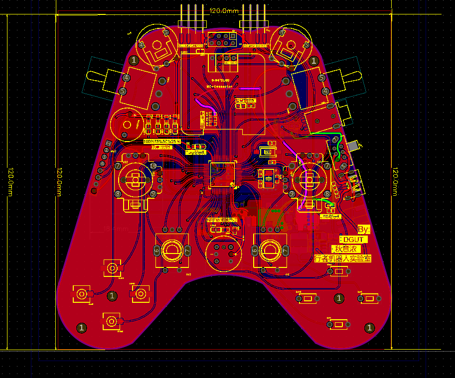
PS: This PCB uses the arc wiring method for single-path wiring for the first time. The overall layout wiring does not look very good at first glance. Please forgive the trouble caused to everyone. This board is designed with a 2-layer board. I will not introduce the PCB in detail. The main point is that the user's hand feel for each function peripheral needs to be properly matched with our layout design to enhance the user experience. The copper transparency is 30%. The traces of other modules will not be explained in detail. The layout wiring of the power supply part will not be specifically extracted here.
Software Description
(P.S.): The code may not be very well written, certainly not as good as the software experts on my team. Criticism and corrections are welcome! Also, this is only for debugging peripheral demos and is only applicable to bare-metal code without an operating system. FreeRTOS will be open-sourced after improvement.
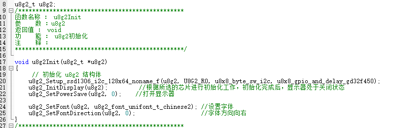
① U8g2 Code Block API (GD32F450 compatible with F429) :
U8g2_Init,
U8g2_Progress (progress bar
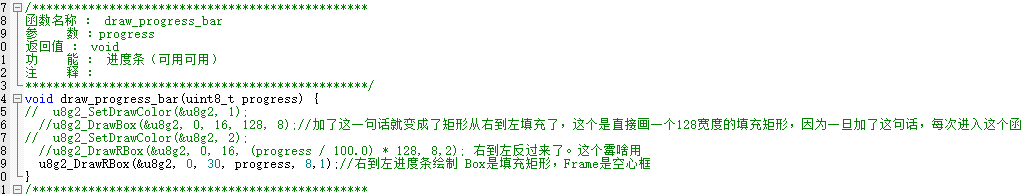
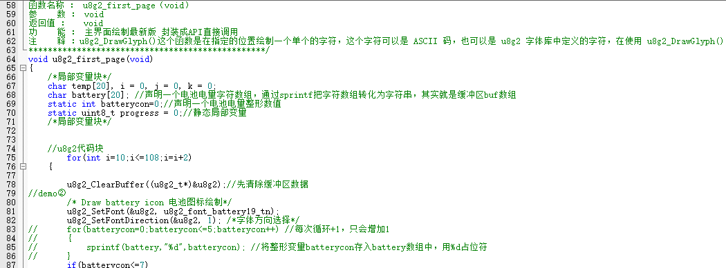
), U8g2_Draw Battery Icon , U8g2_Main Interface
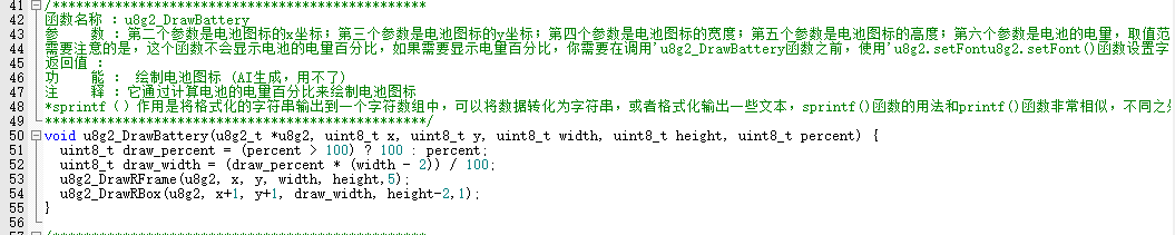
(UI including battery level display, progress bar, and related parameter information),
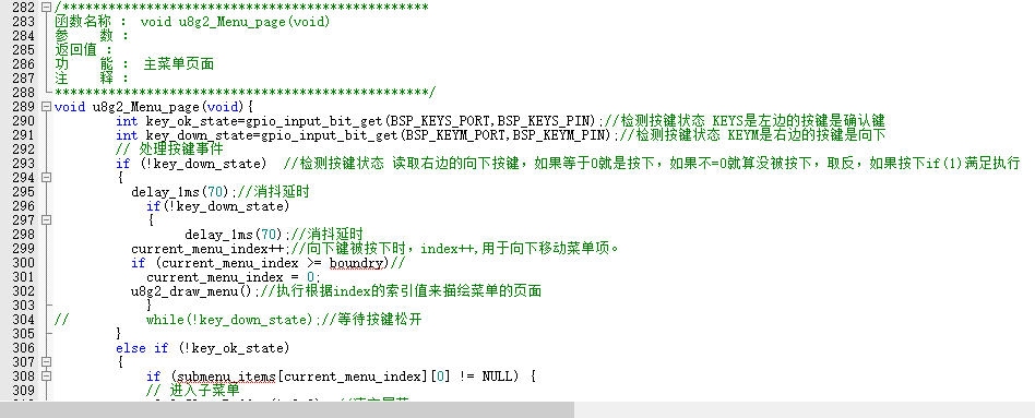
U8g2_Three-Level Menu Interface API:

U8g2_Handling Submenus of Multi-Level Menus by Key Index Value.
Main Function: Variable Definition Page
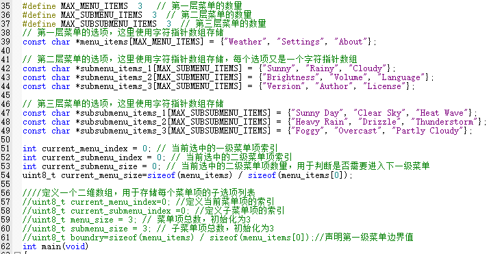
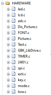
(HARDWARE folder section):
Debugging Log:

! ... The following only introduces the key peripherals:
24L01.c,

TIM3_IRQHandler(),

Mode.c

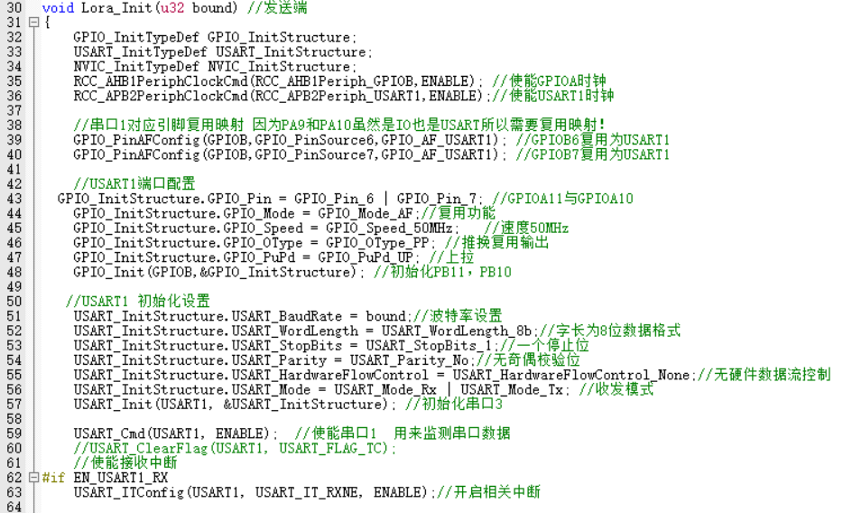
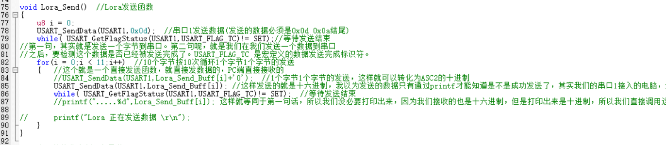
, Lora.c
, KEY.c

, SPI.c

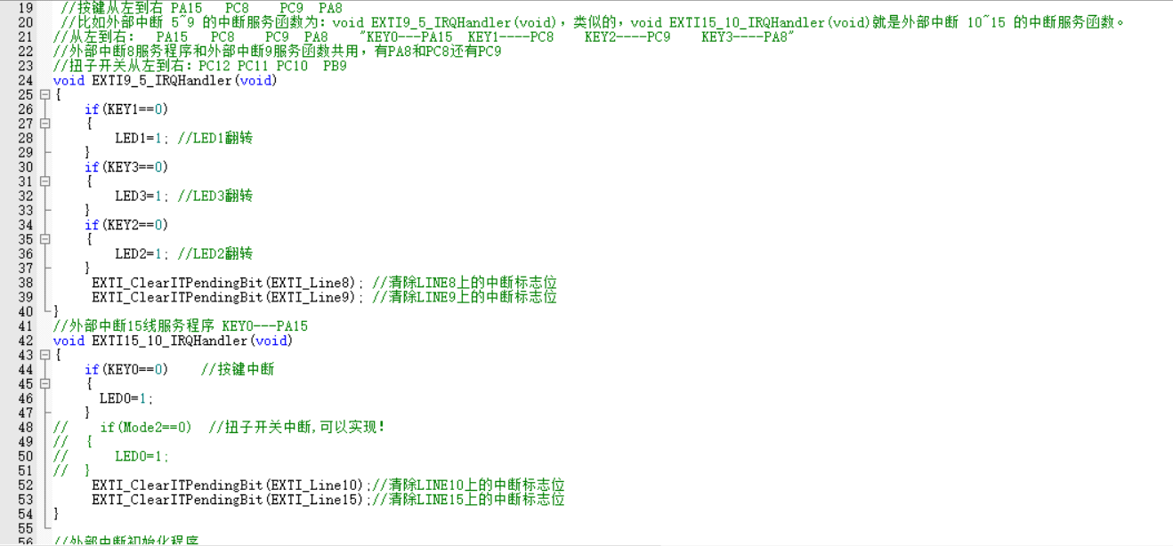
, and EXTI.c.
u8g2.zip
PDF_Multi-channel RC Remote Control Test Board [Color Silkscreen].zip
Altium Multichannel RC Remote Control Test Board [Color Silkscreen Printing].zip
PADS Multi-Channel RC Remote Control Test Board [Color Silk Screen Printing].zip
BOM_Multi-channel RC Remote Control Test Board [Color Silkscreen Printing].xlsx
91080
QMK Shaped Mechanical Keyboard
A keyboard that suits your usage habits. It may have an unusual layout, a unique height, or unconventional key functions, but no matter what, it is uniquely yours.
Design Purpose:
To design a keyboard that suits your personal usage habits. This involves designing a keyboard specifically tailored to your own habits and needs. It might have an unusual layout, a unique height, or unconventional key functions, but no matter how unusual it may seem, it's a structure and function specifically designed for your needs. This is perhaps the charm of customization.
Detailed production tutorial (see attachment).

Design Requirements:
Layout, Customizable
, Cool RGB
Keys, Online Key Customization
Support, Macro Definitions,
Hot-swappable
Type-C Interface.
Hardware Selection
: Controller: STM32F103/APM32F103
, LEDs: WS2812B (6028 reverse-mount 4-pin),
Switches: Kailh.
Software Development:
QMK Firmware
(Vial).
Hardware Design:
Controller:
Considering support for Vial firmware and various lighting effects, a high-performance 32-bit microcontroller was chosen. The domestic APM32F103CBT6 was selected.
The minimum system of the APM32 is relatively simple, requiring only necessary power supply, clock, and a reset button.
It's important to note that when flashing the firmware after creation, a bootloader is used. To avoid re-flashing the bootloader after each firmware update, boot0 must be grounded.

The power supply is crucial; considering the keyboard's small size, the chosen LDO chip , the RT9193, is selected for its
minimal external circuitry and compact design. The mainstream Type-C interface is used for easy connection. Because the keyboard communicates with the computer via USB, the USB_D+ needs to be pulled up with a 1.5k resistor according to design requirements. Why is a pull-up resistor necessary, and specifically 1.5k? Refer to online resources for an explanation: How does the USB host detect the inserted device? On each downstream port of the USB hub, a 15K pull-down resistor is connected to ground on D+ and D-. This way, when the hub port is floating and no device is plugged in, the input is pulled low by these two pull-down resistors. On the USB device side, a 1.5K pull-up resistor is connected to 3.3V power supply on either D+ or D-. Whether the 1.5K pull-up resistor is connected to D+ or D- depends on the device speed. For full-speed and high-speed devices, the pull-up resistor is connected to D+, while for low-speed devices, the pull-up resistor is connected to D-. When a device is plugged into the hub, the voltage on the data line connected to the pull-up resistor is determined by the voltage division of the 1.5K pull-up and 15K pull-down resistors, resulting in approximately 3V (3.3/1.5+15)*1.5=3V). This is a high-level signal for the hub's receiver. Upon detecting this state, the hub reports it to the USB host controller, thus detecting the device insertion. The hub determines the speed type of the inserted device based on whether the pulled-up data line is D+ or D-. High-speed USB devices are initially identified as full-speed devices. After confirmation through communication between the hub and the device, it switches to high-speed mode. In high-speed mode, current transmission is used, and the pull-up resistor on D+ is disconnected. If this 1.5K value is different, the voltage level after the D+/D- pull-up division will change. If voltage ripple is encountered, it may not be detected; this is the origin of the 1.5K value. The buttons are hot-swappable and use Kailh hot-swappable connectors. Keyboard key connections generally fall into two categories: 1. Matrix connection and 2. Independent connection. The goal of this design is to create a small-array keyboard, and since the AMP32 has sufficient I/O ports, an independent connection is adopted. This method eliminates the need for diodes, reducing costs. The LEDs are driven by WS2812B (6028 reverse-mount 4-pin) via PWM signals. The LEDs are connected in series. During the design, remember to connect the signal input pins to the pins on the microcontroller that can output PWM signals. Do n't forget to reserve the programming pins. ST-LINK is recommended for programming. For the keyboard firmware design , based on the initial keyboard requirements, instead of developing our own, we chose the open-source keyboard firmware QMK. We also used VIAL instead of VIA. This is why a higher-performance chip was chosen. Note that because VIAL is used, you need to download the code from the corresponding VIAL branch, not the main repository. The vial_qmk source code and VIAL tutorial are available on the QMK website. It supports various keyboards and features such as knobs and screens. This design only uses the most basic key functions. This is a small, practical layout. The development environment first requires the QMK MSYS software. QMK maintains a package based on MSYS2, with all command-line programs and dependencies included. The development environment can be quickly started using QMK MSYS shortcut commands. Next, you need to obtain the QMK source code. Due to certain reasons, please resolve network issues yourself. When obtaining the source code, because the project contains many submodules, it is not recommended to download each submodule individually via Git. Note that directly downloading a ZIP file from the GitHub web interface can also result in incomplete submodule downloads. It is recommended to use the GitHub desktop application for downloading; this method eliminates the need to consider the impact of submodules. After obtaining the source code, test your development environment using QMK MSYS. For example, the following code: `qmk compile -kb clueboard/66/rev3 -km default`. If you see no errors and the .hex file is successfully generated, the development environment is set up and you can proceed with further development. Linking: `.build/clueboard_66_rev3_default.elf [OK] Creating load file for flashing: `.build/clueboard_66_rev3_default.hex [OK]`


Copying clueboard_66_rev3_default.hex to the qmk_firmware folder [OK]
Checking the file size of clueboard_66_rev3_default.hex [OK]
* The firmware size is fine - 26356/28672 (2316 bytes free)
Code writing:
Open the QMK source code with any code editor.
The QMK project structure is as follows:
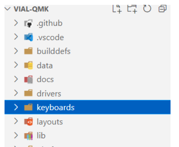
We only care about the contents of the keyboards folder, which contains many other keyboards developed by others, and we can also use them for reference.
Create the following
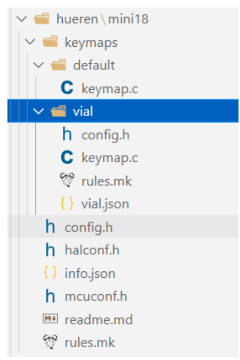
file structure
under the keyboards folder
:
... Run `python3 util/vial_generate_keyboard_uid.py` from the root directory of vial-qmk to generate a unique Vial keyboard ID. Ensure your computer has a Python environment. `#pragma once define VIAL_KEYBOARD_UID {0x9A, 0x27, 0xBD, 0x85, 0x42, 0xBD, 0x97, 0x56} keymap.c` is the same as above . `rules.mk` is used to enable Vial under the rules: `VIAL VIA_ENABLE = yes` ` VIAL_ENABLE = yes` ` VIAL_INSECURE = yes` `VIALRGB_ENABLE = yes` `vial.json` The first step in creating the Vial port is to prepare the keyboard definition, which is a JSON file describing the keyboard layout. Fill in the corresponding content according to the following template: `{ "lighting": "vialrgbe", "matrix": { "rows": 4, "cols": 4 }, "layouts": { "keymap": } }` The content of `keymap` needs to be retrieved from the keyboard design website. Enter the corresponding coordinates on the blank keyboard. After filling in the coordinates as shown in the image below, copy the contents of the Raw data file and paste them into it . Configure the number of LEDs, DMA channels, and other related settings in config.h . Refer to the manual for detailed configuration instructions. // Copyright 2023 HiryKun (@HiryKun) // SPDX-License-Identifier: GPL-2.0-or-later pragma once define BOOTMAGIC_LITE_ROW 0 define BOOTMAGIC_LITE_COLUMN 3 define WS2812_PWM_DRIVER PWMD2 define WS2812_PWM_CHANNEL 4 define WS2812_DMA_STREAM STM32_DMA1_STREAM2 define WS2812_DMA_CHANNEL 2 define RGB_MATRIX_LED_COUNT 15 define RGB_MATRIX_FRAMEBUFFER_EFFECTS define RGB_MATRIX_KEYPRESSES define NO_USB_STARTUP_CHECK halconf.h to enable the STM32 function. #define HAL_USE_PWM TRUE #define HAL_USE_PAL TRUE define STM32_HAS_USB TRUE include_next info.json The main keyboard configuration corresponds to the physical connections between the keys and the microcontroller pins. It is written in matrix form, with NO_PIN used to fill in missing keys. "matrix_pins": { "direct":[ ["B14","B15","B5","B3"],


["B13","B12","B1","A7"],
["B0","NO_PIN","NO_PIN","NO_PIN"],
["A6","NO_PIN","NO_PIN","NO_PIN"]
]
},
Keyboard layout definition. The layout should be consistent with the previously designed layout.
"layouts": {
"LAYOUT": {
"layout": [
{"matrix": [0, 0],"x": 0,"y": 0},
{"matrix": [0, 1],"x": 1,"y": 0},
{"matrix": [0, 2],"x": 2,"y": 0},
{"matrix": [0, 3],"x": 3,"y": 0},
{"matrix": [1, 0],"x": 0,"y": 1},
{"matrix": [1, 1],"x": 1,"y": 1},
{"matrix": [1, 2],"x": 2,"y": 1},
{"matrix": [1, 3],"x": 3,"y": 1,"h": 2},
{"matrix": [2, 0],"x": 0,"y": 2,"w": 2},
{"matrix": [3, 0],"x": 0,"y": 3,"h": 2}
]
}
}
RGB related configuration
lighting effects. Enter the lighting effects you want to enable here.
The more lighting effects, the larger the firmware size, so choose a high-performance microcontroller initially.
"animations": {
"alphas_mods": true,
"gradient_up_down": true,
"gradient_left_right": true,
"breathing": true,
"band_sat": true,
"band_val": true,
"band_pinwheel_sat": true,
"band_pinwheel_val": true,
"band_spiral_sat": true,
"band_spiral_val": true,
"cycle_all": true,
}</code></pre>
Illuminator position settings. For detailed instructions, please refer to the document
"center_point": [32,32],
"layout": [
{"flags": 4, "matrix": [1,0], "x": 0, "y": 0},
{"flags": 4, "matrix": [1,1], "x": 21, "y": 0},
{"flags": 4, "matrix": [1,2], "x": 43, "y": 0},
{"flags": 4, "matrix": [1,3], "x": 64, "y": 0},
{"flags": 4, "matrix": [2,3], "x": 64, "y": 21},
{"flags": 4, "matrix": [2,2], "x": 43,{"y": 21},
{"flags": 4, "matrix": [2,1], "x": 21, "y": 21},
{"flags": 4, "matrix": [2,0], "x": 0, "y": 21},
{"flags": 4, "matrix": [3,0], "x": 0, "y": 43},
{"flags": 4, "matrix": [3,1], "x": 21, "y": 43}
]</code></pre>
RGB drive signal output pin
"ws2812": {
"driver": "pwm",
"pin": "A3"
}
mcuconf.h
mainly enables the peripherals needed by STM32
#include_next
undef STM32_PWM_USE_TIM2
define STM32_PWM_USE_TIM2 TRUE
undef The basic keyboard firmware code is now defined as STM32_PWM_USE_TIM1 TRUE. After compilation using QMK MSYS, firmware in .BIN and .HEX formats can be generated
.
db544a350abb53bfd50dafe9134c3a49.mp4
bootloader.zip
st_link utility.zip
qmk_toolbox.zip
A Beginner's Guide to Keyboard DIY Tutorial.zip
keyboard.zip
Keyboard source code.zip
Keyboard Firmware V1.0.0.zip
Accessories purchase reference link.zip
Front and rear back panels (positioning plates).zip
Tag number diagram.zip
Vial-v0.7-Portable.zip
PDF_QMK Irregular Mechanical Keyboard.zip
Altium_QMK Shaped Mechanical Keyboard.zip
PADS_QMK Irregular Mechanical Keyboard.zip
BOM_QMK Irregular Shaped Mechanical Keyboard.xlsx
91081
CH582M Tri-mode Basic PAD
Based on Qinhengjia CH582, a tri-mode entry-level PAD
/************************************************************************************************************/
Update
2023/3/22:
Uploaded the project file "Tri-mode PAD Basic Version.zip". The software used for development is MountRiver. Welcome to create branches to add
features to the PAD or port it to keyboards with different layouts.
2023/3/23:
Updated notes on purchasing components. If you are confused by strange BOM lists, you can take a look.
2023/3/24:
Uploaded the firmware for the keyboard and receiver separately.
2023/3/31:
After testing by group members, the receiver should ideally be 0.8mm thick and green so it can fit into a discarded receiver casing.
2023/7/19:
Thanks to yuan_kj The RGB code added by the expert
has been adapted to the PCB of this project. You only need to burn the "PAD Motherboard RGB Firmware" in the attachment to the keyboard to make it light up.
The latest project compressed package has also been uploaded to the attachment.
2023/8/9:
A few days ago, when writing the code for the tri-mode 61, I found the reason for the frequent Bluetooth disconnections that occurred before. It has been fixed and uploaded to the attachment, "Tri-mode 17RGB (Bluetooth Fix)".
However, the finished keyboard is not with me, and the code has not been verified.
If your keyboard experiences frequent Bluetooth/2.4G disconnections or other malfunctions, you can try using the motherboard firmware in the new project file
.
This is a tri-mode version of the most basic keyboard
(though it lacks touch functionality).
It is perfectly compatible with the basic 17+4's shell and mounting plate, retaining the valuable free shell and mounting plate.
The frame and switch layout are taken from the most basic 17+4TPRO mechanical keyboard - JLCPCB EDA Open Source Hardware Platform (oshwhub.com).
The program is modified from Qinheng's sample program.
Related projects include CH579M Dual-Mode Basic PAD - JLCPCB EDA Open Source Hardware Platform (oshwhub.com).
Function Demo: C3H4O Dynamics - Bilibili (bilibili.com).
Function Description:
The side button is boot. Pressing boot powers on and enters download mode.
boot+/ enters USB mode, with two mode indicator lights lit. Wired connection:
boot+* Entering Bluetooth mode, one mode indicator light will illuminate, indicating the Bluetooth name is 3modekeyboard.
Bluetooth can save four hosts. Another mode indicator light will illuminate. Press boot + 1/2/3/enter to quickly switch between paired hosts.
Press boot + 4/5/6/+ to delete paired host information and enter Bluetooth pairing mode.
boot + - enters 2.4G mode. If it is the first time using it, simply insert the receiver to complete pairing (or press boot + 8 to pair).
Different colored indicator lights indicate the mode, NUMLOCK, charging, and main control power supply status.
The four additional buttons on top are ESC, TAB, PrintScreen, and Backspace
to save the mode at the last power failure.
Soldering and programming precautions:
It is best to use different colored indicator lights (at least three mode indicator lights should be different)
. CH582 is in QFN package. Soldering is relatively difficult, so it is recommended to solder the receiver first. Observe for any bridging or cold solder
joints before soldering other components.
For receiver prototyping, be sure to choose 0.8mm thick, green solder mask (non-green thickness is not free). The software used for programming is Qinheng's WCHISPTool (attached).
After opening the software, press the keyboard boot button and plug it into the computer to enter download mode.
Generally, the first download does not require pressing the boot button, so you can judge whether the soldering is fine by whether it is recognized after power-on.
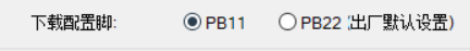
When programming the receiver, be sure to check PB11 as the download configuration pin, as shown in the figure below. When programming the keyboard, be sure to select PB22.
Be sure to distinguish between the keyboard firmware and the receiver firmware!
Component purchasing matters:
Do not purchase according to the automatically generated BOM at the bottom of the webpage! I've silkscreened
the names, packages, and purchase links for most of the important components on the keyboard PCB (links to my purchases are provided):
1. Battery Management Chip: TP4056 SOP8 package
2. High-Speed Crystal Oscillator: 32MHz 3225 package
3. Low-Speed Crystal Oscillator: 32.768KHz 3215 package
4. Voltage Regulator Chip: RT9193-33GB SOT-23-5 package
5. Storage Compartment: Recessed USB Female Connector https://m.tb.cn/h.UqIMYwu?sm=b4ca00?tk=EI0PdQn604S
6. Recessed Tactile Switch: https://m.tb.cn/h.UrUsDE8?sm=f4b7fc?tk=iCZhdQni3p6
7. Toggle Switch: 7-Pin Toggle MSK-12C01-07
Important component names, packages, and purchase links for the receiver PCB (link provided for my purchases): 1.
Crystal oscillator: 32M 2016 package
2. Voltage regulator chip: XC6206P332MR SOT-23 package
For any other components, if unsure, open the PCB editor in the upper right corner and purchase the components listed.
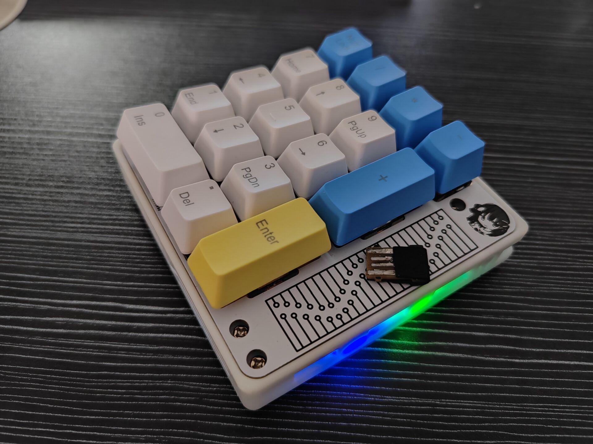
Finished product image:

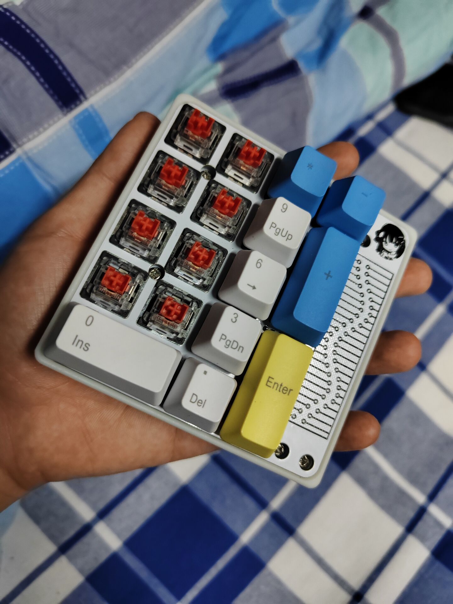
Perfectly compatible with the basic 17+4 casing and positioning board.
The remaining space on the bottom shell can only accommodate a thin battery of about 500mAh.
The receiver is difficult to solder (it's very small and has two surface-mount capacitors on the back).

This keyboard is currently just a pure tri-mode PAD
, but the hardware has reserved a touch area, which may be added in a future update (creating a new folder).
Looking forward to help from experts!
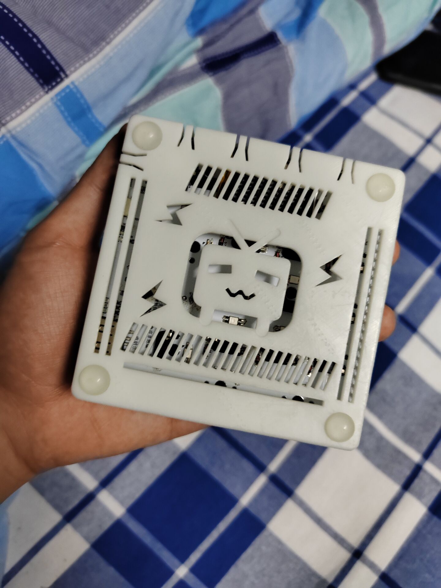
Shell_Button Integration.stl
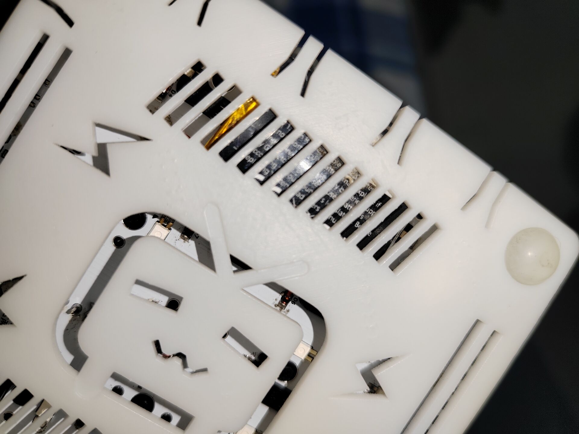
For group members, a hollowed-out version of the TV casing.
Receiver firmware.hex
PAD motherboard RGB firmware.hex
Tri-mode PAD RGB version.zip
Tri-mode 17RGB (Bluetooth fixed).hex
PDF_CH582M Tri-mode Basic PAD.zip
Altium_CH582M Tri-mode Basic PAD.zip
PADS_CH582M Tri-mode Basic PAD.zip
BOM_CH582M Tri-mode Basic PAD.xlsx
91082
Modular PWM fan control board
Modular PWM fan control board
This modular design controls four 12V DC PWM speed-regulating fans.
It can be connected to the motherboard via connectors or integrated into the circuit.
Reserved address bits allow for setting the board address, enabling multiple boards to connect to the motherboard.
A reserved communication interface allows for motherboard control.
An onboard temperature module monitors ambient temperature in real time. An external temperature module is placed in the temperature monitoring position to monitor temperature and adjust fan speed. The
speed regulation uses an isolated design for enhanced stability and safety.
The single-sided component design facilitates soldering.
PDF_Modular PWM Fan Control Board.zip
Altium Modular PWM Fan Control Board.zip
PADS Modular PWM Fan Control Board.zip
BOM_Modular PWM Fan Control Board.xlsx
91083
electronic
 4. There are two 3D model files: one for the main control board and one for other luminous modules.
 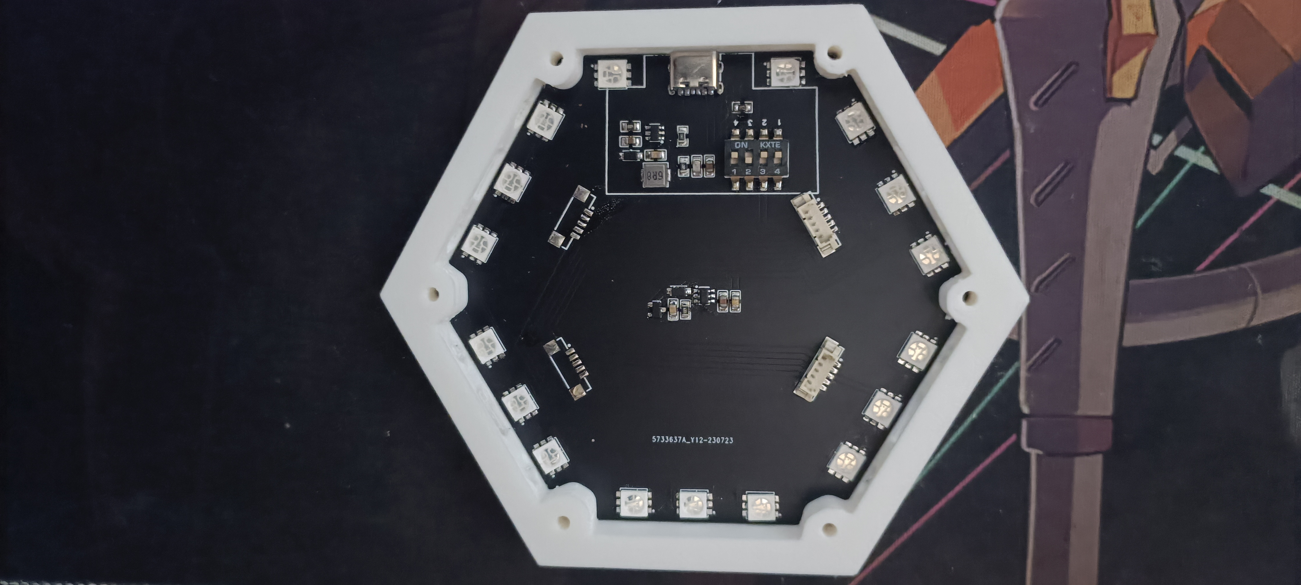 8. The attachments include some purchase links and 3D printing files (25% infill for 3D printing).
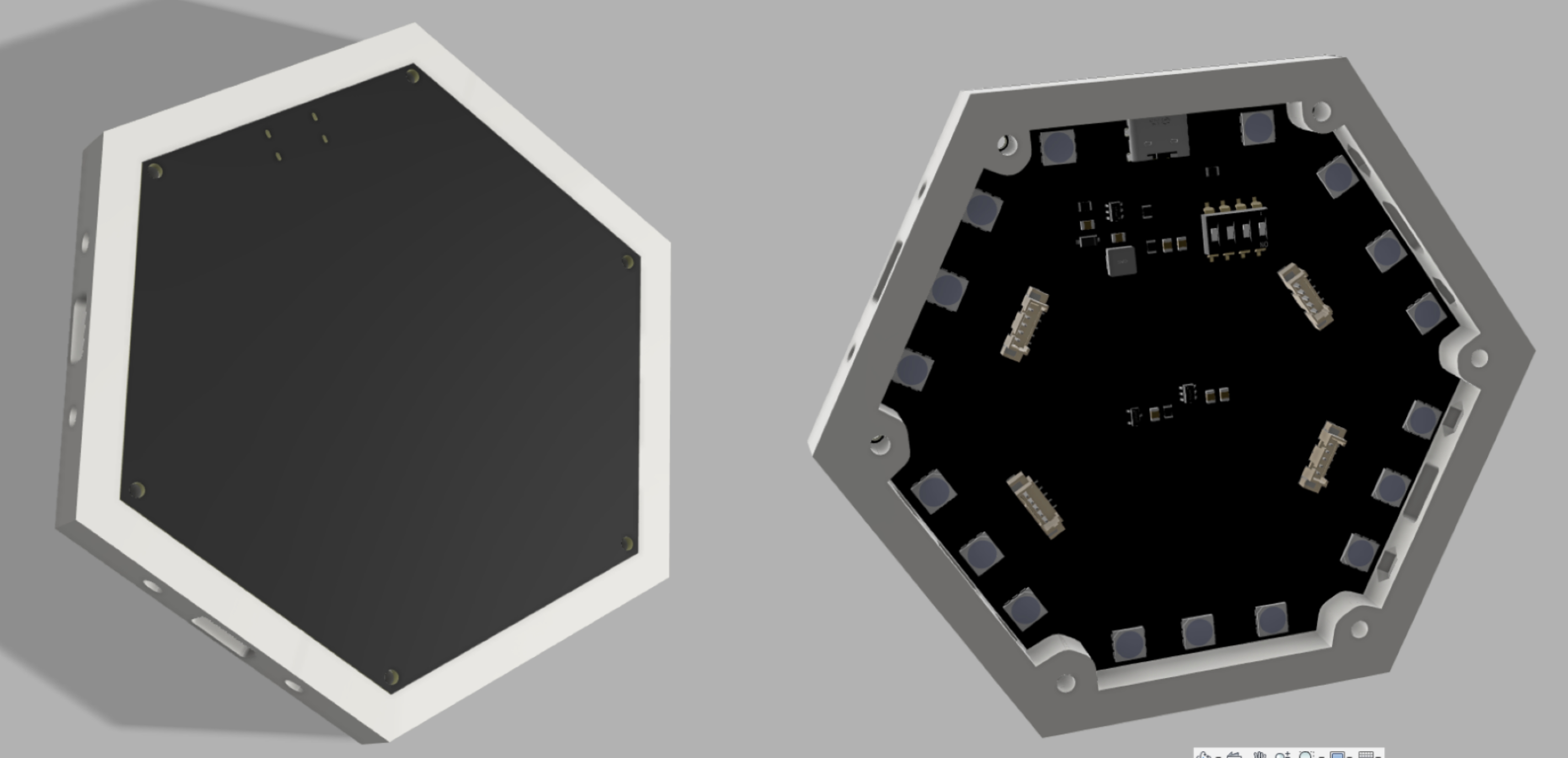

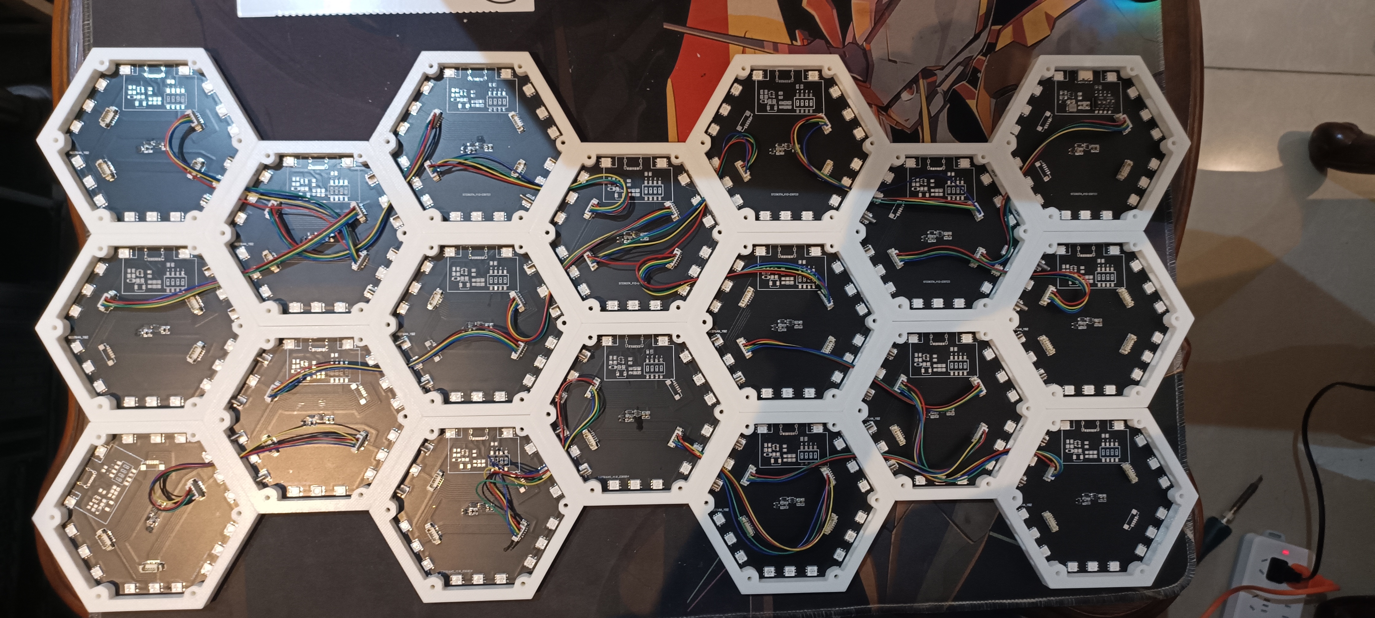
 diagram is as follows: It's relatively simple.
  2. Core Component
 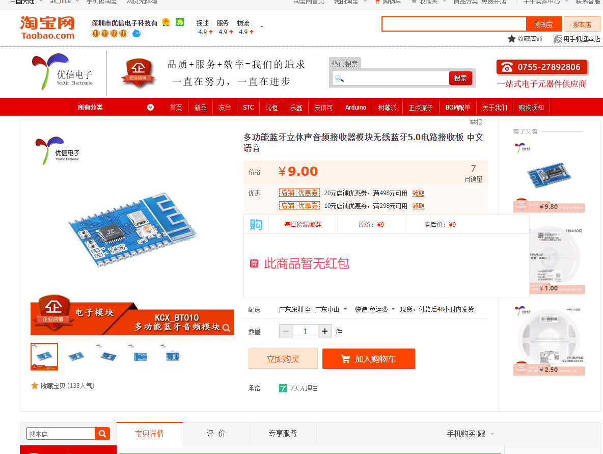 3. EQ Recommendation:
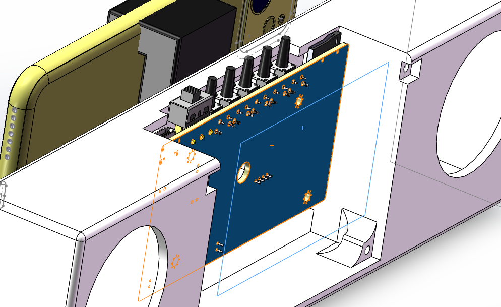
  4. Shell Design: Used in SW design, see attachment: 3D.7z independent cavity shell for
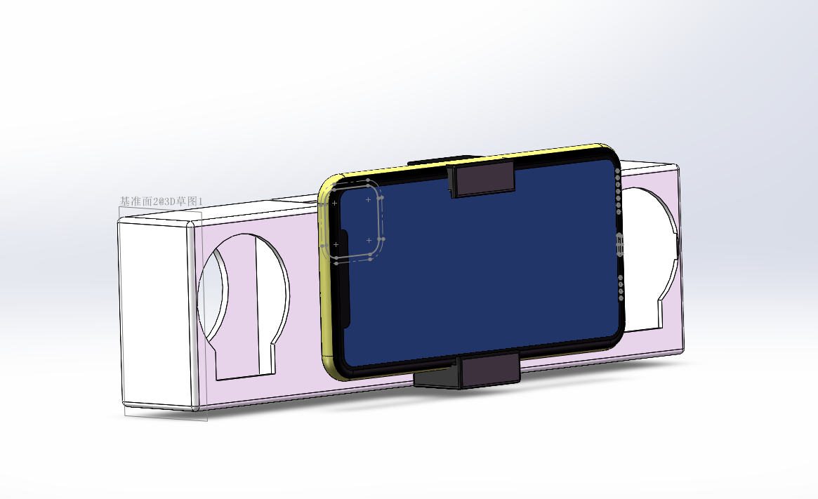
 System Block Diagram :
 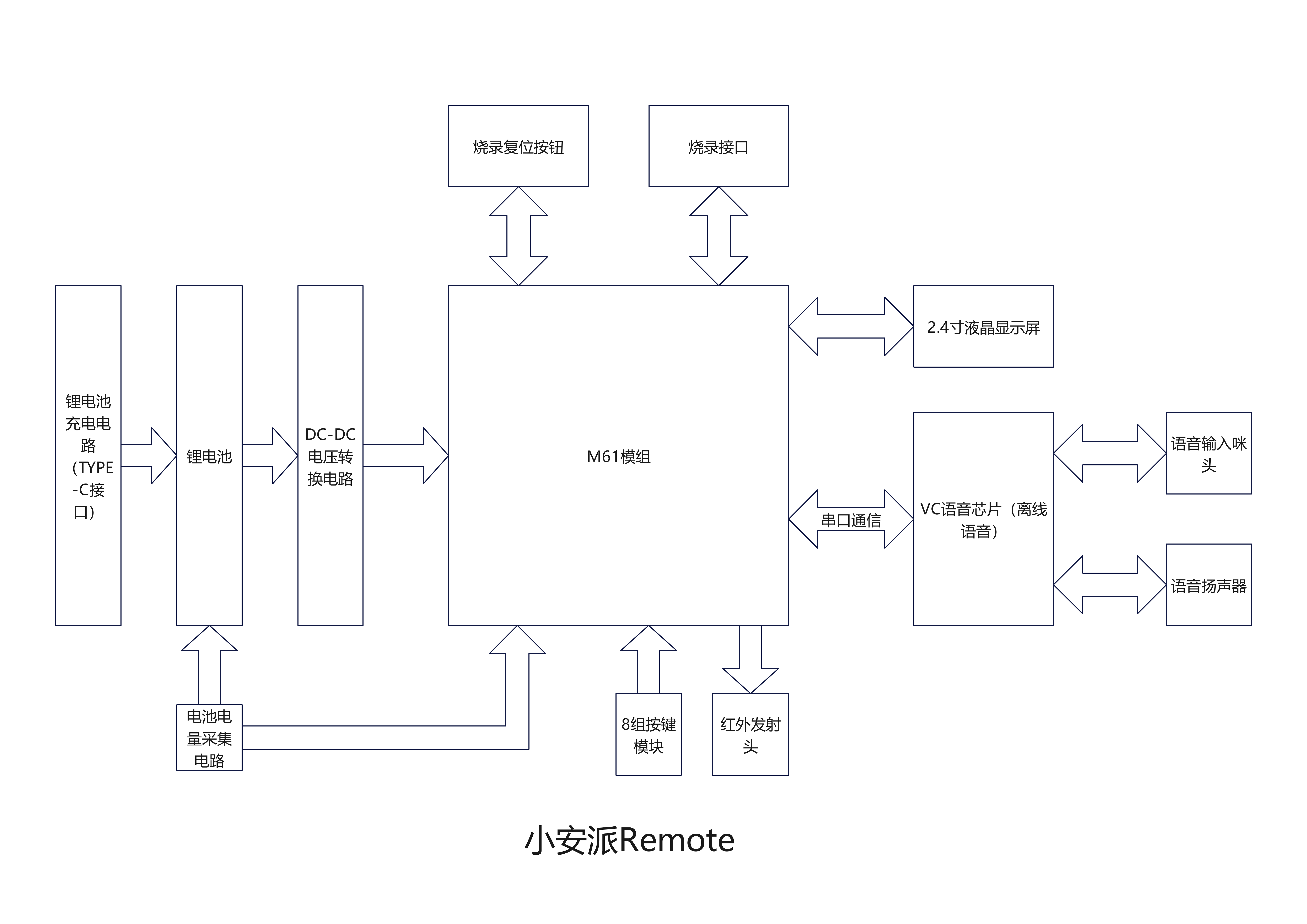 2.4-inch Touchscreen LCD Display
 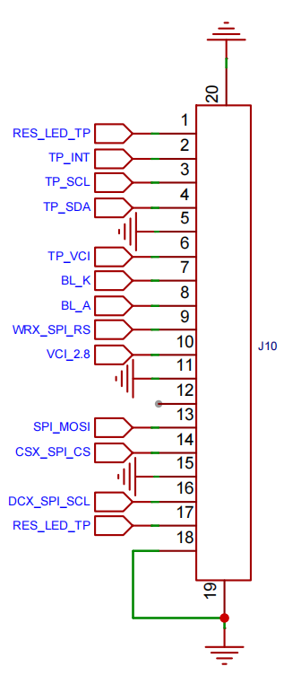 VC Voice Chip:
 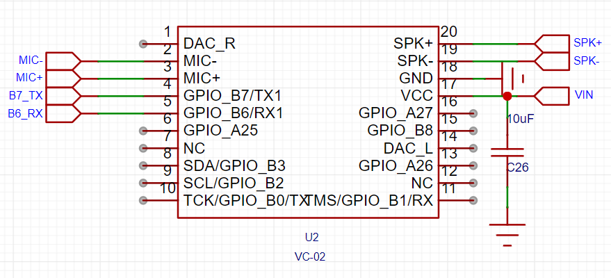 Infrared Transmitter:
  Charging Circuit:
 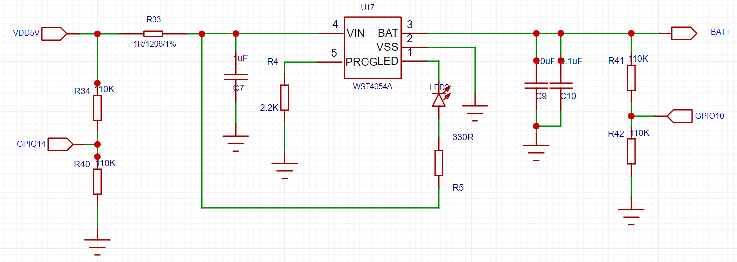 Eight independent buttons
  Offline voice list:


 京公网安备 11010802033920号

 PIC24HJ256GP506AI/PF


