Video Link:
[Bilibili Video - Function Demonstration and Introduction] https://www.bilibili.com/video/BV1D7HyeREbs/?spm_id_from=333.999.0.0&vd_source=62041db00a9b73e7a58c0c0c170a1625
Detailed data package file is too large, please send a private message to obtain it!
Recent Updates:
1. Due to the discontinuation of the previous version chip, it is not recommended to remake it if the chip is unavailable!
2. 20241105: Redesigned circuit diagram, version: AI117_0.1; removed built-in lithium battery, reduced components! Added timer to turn off the light!
Project Introduction
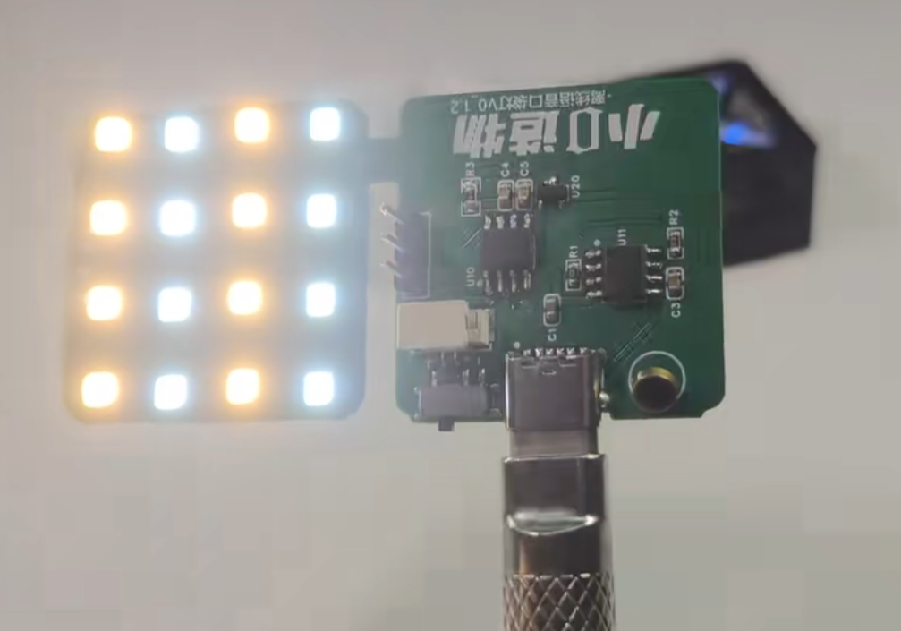
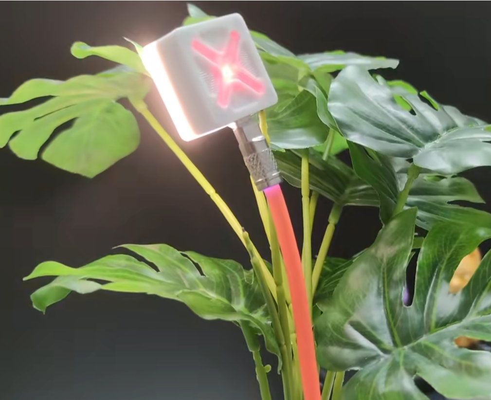
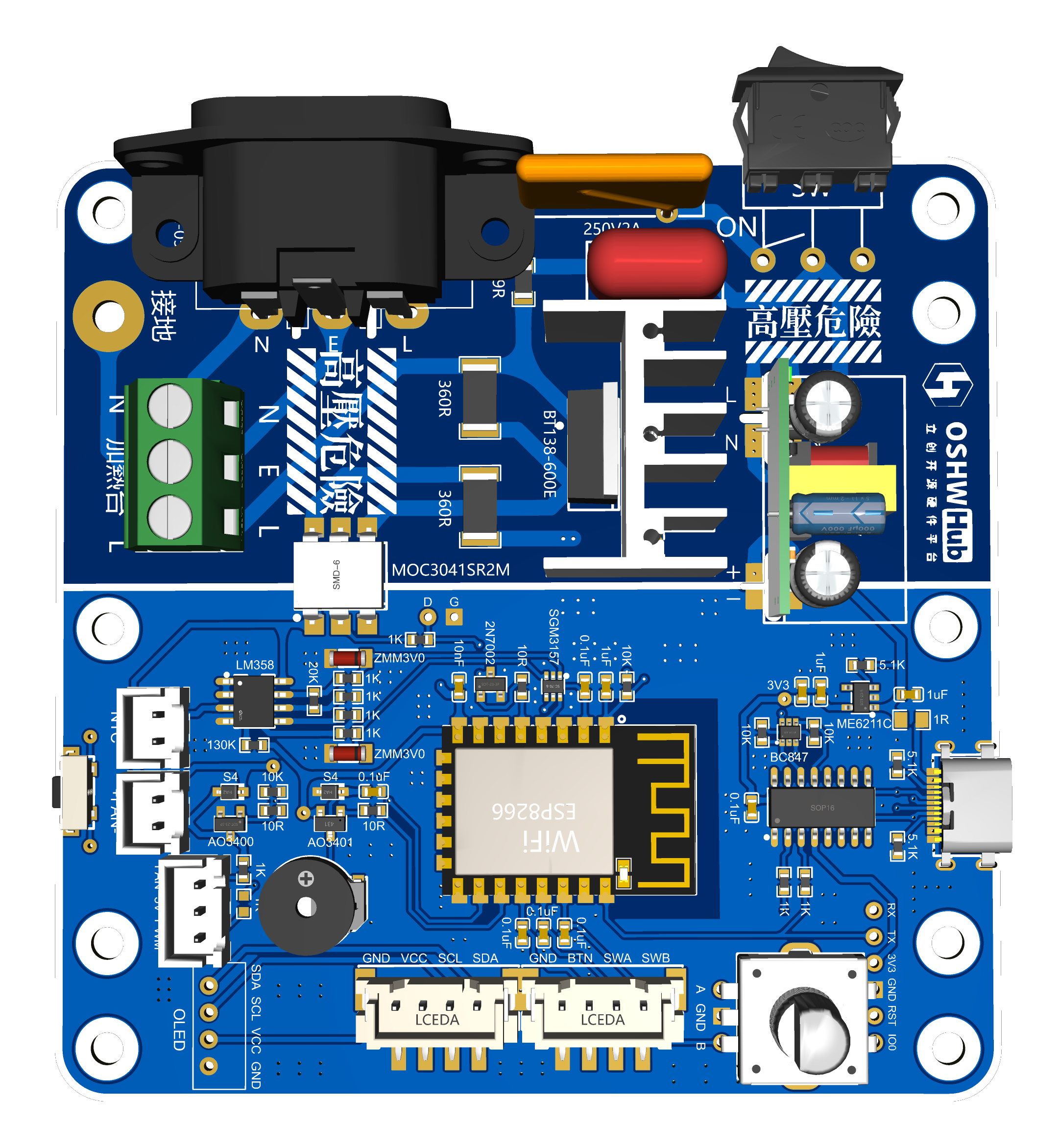
This project is an offline voice night light developed based on an offline voice chip + microphone, using Schottky diodes to build a dual power supply circuit.
No wake-up word required, zero code, no programming, no network connection required, no Bluetooth connection required, ready to use, adjustable brightness/color temperature, magnetic attraction, and memory function.
Features include
voice control: no wake word required, zero code, no programming, no internet connection or Bluetooth connection needed, just use it directly; adjustable brightness/color temperature, magnetic back for attaching to metal surfaces.
Turn on lights: Turn on the lights, I'm home, turn on the lights, etc. Turn off lights: Turn off the
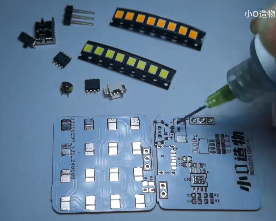
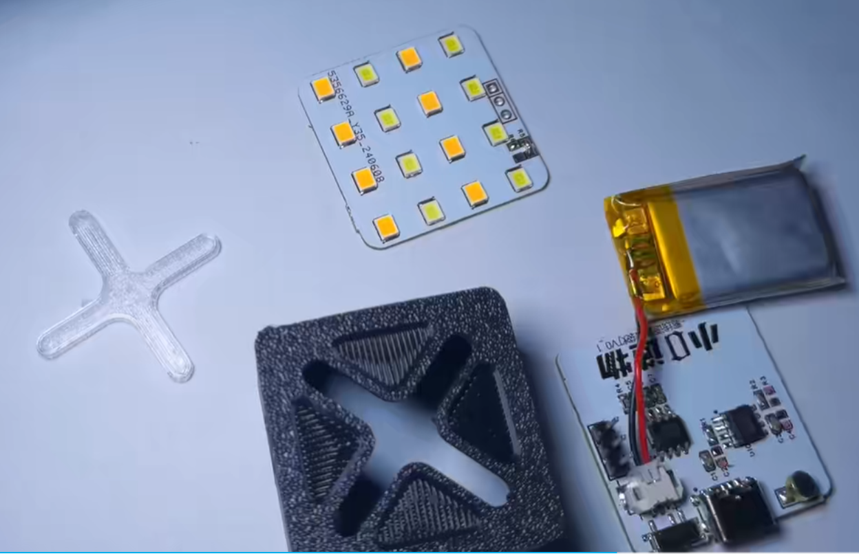
lights, I'm going out, turn off the lights, etc. Adjust color temperature: Change color, change color, change color, etc. Adjust brightness: Brighter/darker, etc. (Flashing reminder when maximum/minimum brightness is reached) [Latest version extended functions are as follows] Going to sleep/Setting a timer for 10 minutes/Setting a timer for 30 minutes/Setting a timer for 1 hour/Cancel timer function Principle analysis (hardware description) I divided the circuit into two parts: control and light board. Control part (the latest version removes the battery): 1 offline voice chip + microphone can realize voice recognition; a dual power supply circuit is built using Schottky diodes; 1 DIP switch, which can disconnect the battery when used for a long time; battery power can also last for several hours; built-in 200 mAh lithium battery; Light board part: Uses 16 2835 LEDs, 8 warm color + 8 cool color, 4 LEDs per group, placed alternately [Old version, chip is discontinued] [Latest Version - External Power Supply] Example Figure 1 (Some circuits have been removed in the latest board): Uses a TYPE-C-6P interface as the power supply interface. Move the DIP switch away from the charging port to disconnect the battery; for battery power, move it closer to the charging port. Example Figure 2: Assembly Flowchart 1: Soldering Figure 2: Component Installation Figure 3: Actual Assembly Diagram


[Open Source] No More Getting Up to Turn Off the Lights.mp4
[Homemade] Offline Voice Night Light.mp4
Offline Voice-Activated Night Light - Power Supply Version Bill of Materials_AI117_0.1_241105.xlsx
PDF_Offline Voice Night Light.zip
Altium Offline Voice Night Light.zip
PADS_Offline Voice Night Light.zip
BOM_Offline Voice Night Light.xlsx
90801
Fan controller used in a certain brand of desktop smoking device.
This desktop fume extractor controller is based on the Qinheng Micro CH32X035. I bought a very expensive desktop fume extractor to absorb the exhaust fumes generated during welding, but I didn't expect that it could only control the fan to turn on and off, and the noise was extremely loud, completely affecting the welding experience. So I developed this fan controller.
The green section
represents the original controller inside the smoking device, featuring two touch buttons and three LED indicators. The touch buttons are used to turn the LEDs and fan on and off.
The white section represents the redesigned fan controller, structurally compatible with the original PCB.


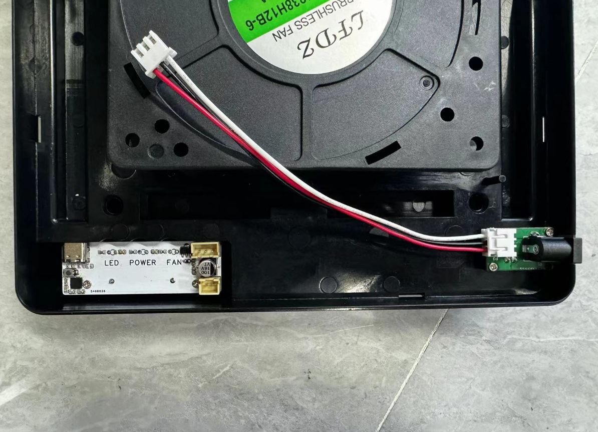
Interfaces, LEDs, capacitors, and touch springs were all directly reused from the original PCB.
The power chip has been replaced with a CJA1117-3.3 to power the microcontroller.
The touch functionality is programmable.
Currently, the function is:
pressing a button gradually increases the fan speed, and pressing the button again at maximum speed turns the fan off. This cycle repeats.
The fan speed program is located in `key_function`. The original code has been modified to:
`if (key_fan_short_flag == 1) { // If the fan button is pressed, execute the following program //function if(pwm_fan == 0) { pwm_fan = 480; } else { pwm_fan += 40; if(pwm_fan > 640) { pwm_fan = 0; } } //function key_fan_short_flag = 0; // Release the button }`
The fan is too noisy at high duty cycles, so it's limited to between 48-64%, where the noise level is acceptable.
The fan speed settings are
: 0
1
2
3
4
5
PWM_DUTY
0
48%
52%
56%
60%
64%.
A short press of the LED button gradually increases its brightness; pressing the button again at maximum brightness turns the LED off. This cycle repeats.
The LED brightness has 10 levels, each increasing by 10%. There's no need to use so many levels; you can modify the code yourself.
Simultaneously, the indicator light synchronously shows the current status, allowing you to determine the current brightness level by the light intensity.
Software:
Download

and install WCHISP_TOOL.
Press the button and then insert the USB; the software will recognize the device.

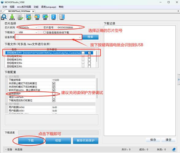
Finally, click download and wait for the programming to complete.
If reprogramming is required, please first download the WCH compilation environment: Mountriver. This is a RISC-V microcontroller compilation and development environment from Qinheng Micro.

Download the CH32X035 series SDK package.

I have already placed the written program in the folder; you can directly open the project.
The project folder is:
xxxxxCH32X035EVTEVTEXAMTIMFan_Control . Two C files are used for
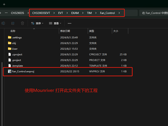
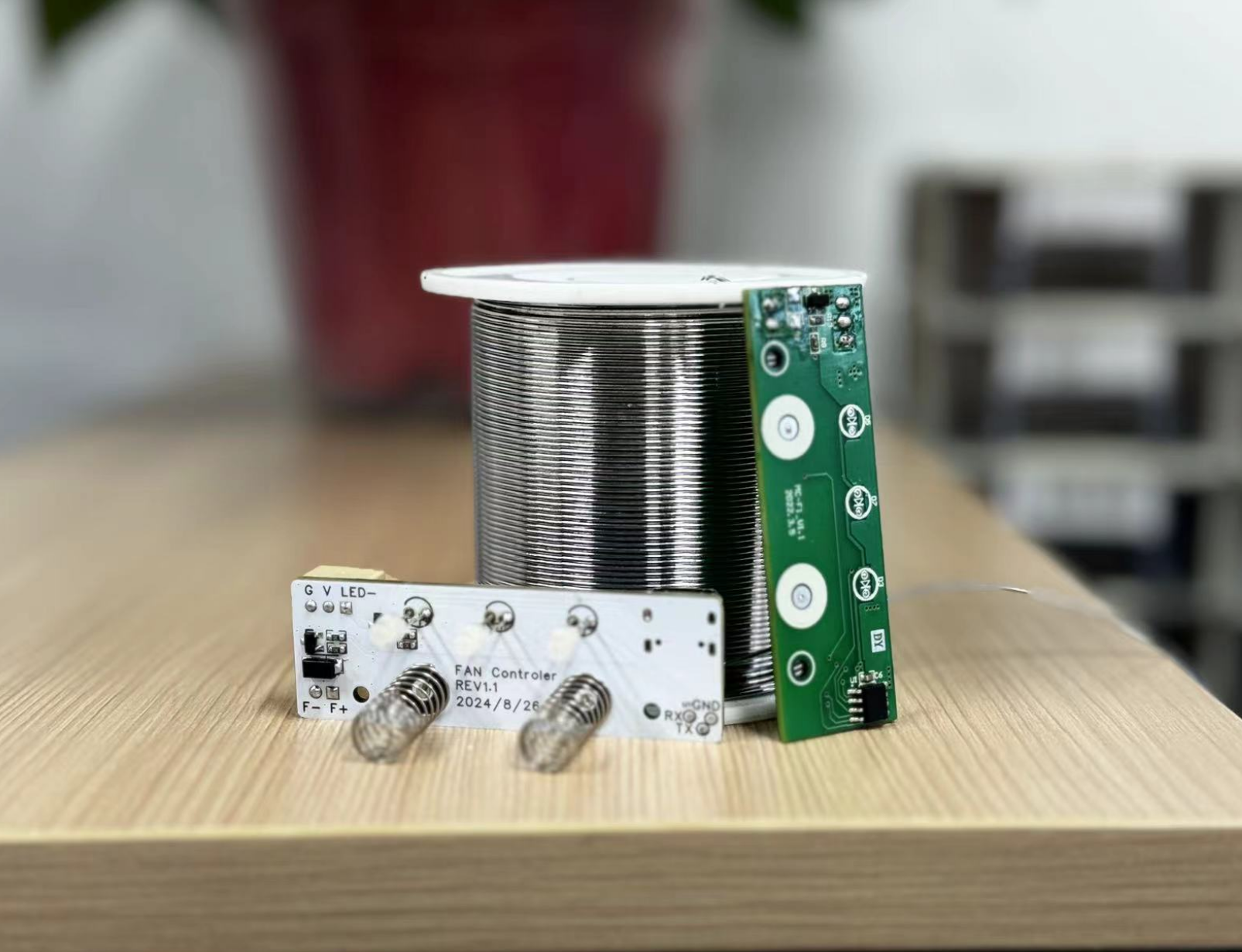
global compilation : one is the interrupt program, containing a 1ms timer interrupt for button timing; the other is the main program, containing system initialization, PWM initialization, etc. A picture of the completed soldered device:


CH32X035EVT_alongxii.zip
PDF_Fan controller for a certain brand of desktop smoking device. .zip
Altium fan controller for a certain brand of desktop smoking device. .zip
PADS fan controller for a certain brand of desktop smoking device. .zip
BOM (Bill of Materials) for the fan controller of a certain brand of desktop smoking device. .xlsx
90802
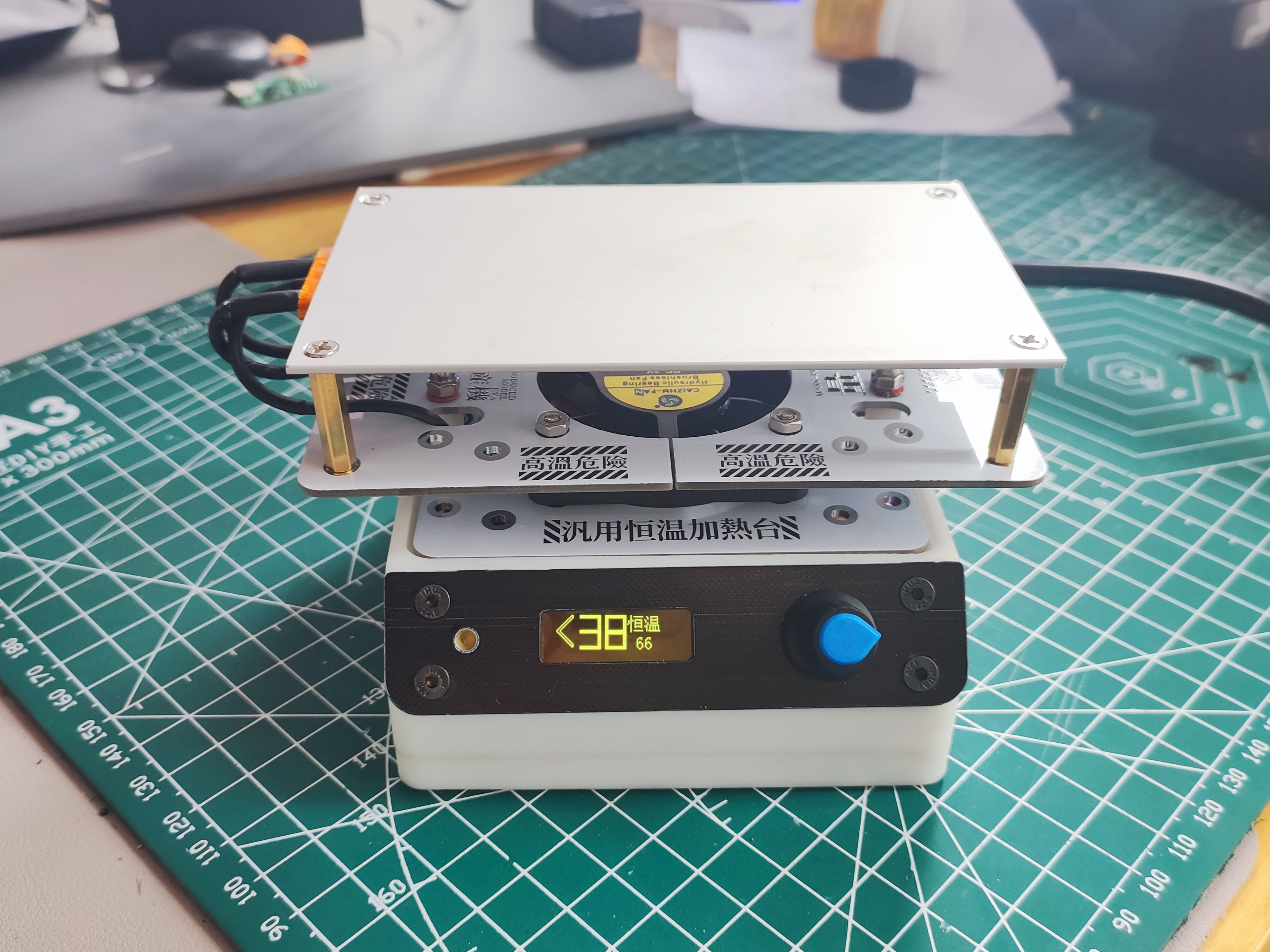
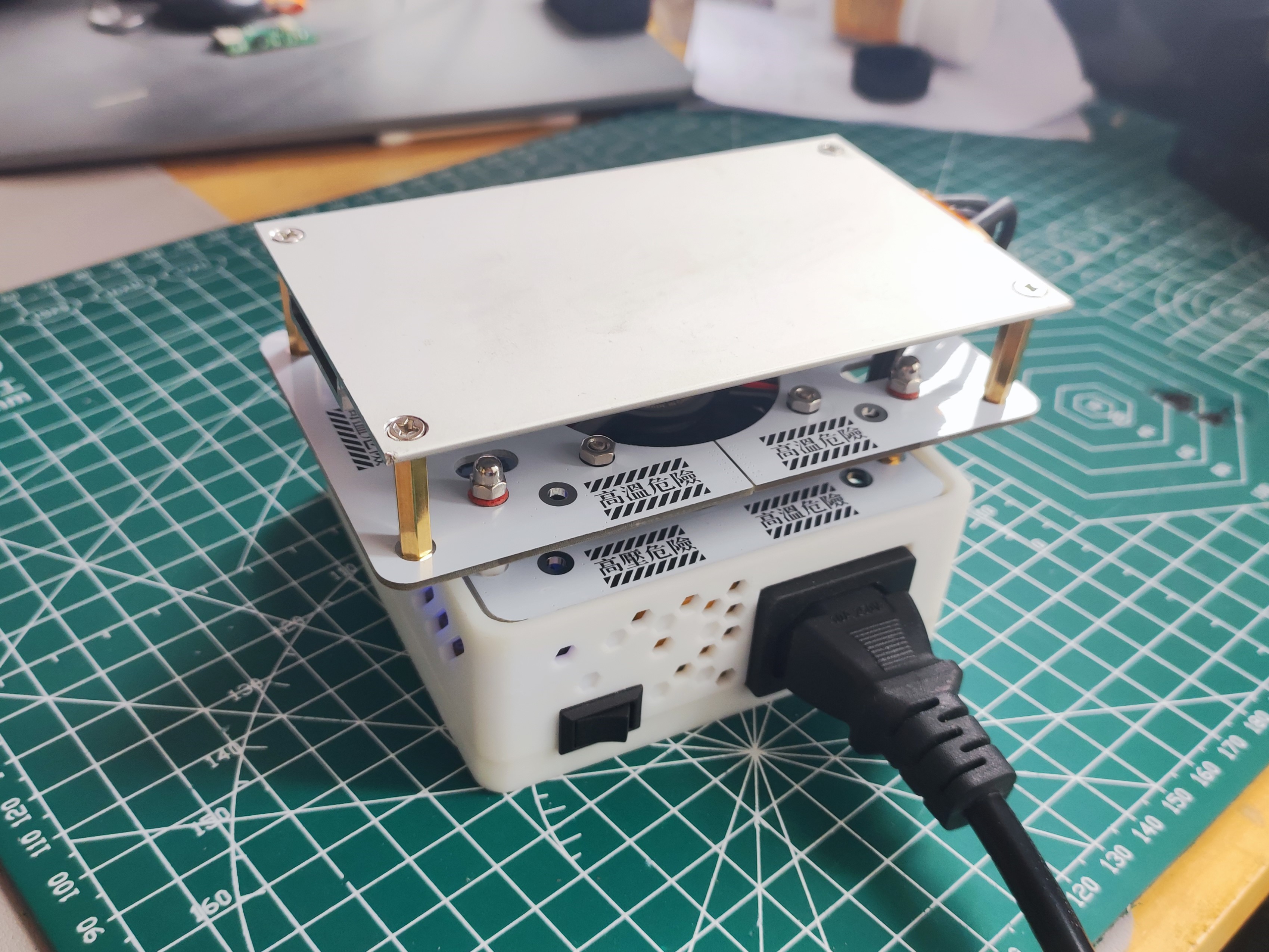
Enhanced version of constant temperature heating platform (modified from the Find Sheep version) 400W
Based on the revised version of "Heating Platform Mass Production Plan - Find Sheep Edition", this version adds a buzzer and heating status display, and includes a 400W panel and a display panel.
August 29, 2024 Update:
I haven't logged in for a long time for some reasons, and I apologize. I found that all my previous comments are gone, and I can't comment under the project anymore; submitting results in an error. This seems to be a bug in the LCSC system, and I'm not sure why LCSC hasn't fixed it. I've also tried re-editing the project, but I still can't comment. I've received many private messages in the backend, all inquiring about the project or requesting modified source code. There are simply too many to reply to individually. I see that Qifan has now released the source code, so that everyone can improve it themselves. Therefore, I'm also releasing my modified source code here. Additionally, I completely redesigned the heating platform's outer shell, modeled after the one from the "Find Sheep" design. It's still compatible with the "Find Sheep" shell; only minor modifications were made. If you've already printed the "Find Sheep" version, you don't need to print it again. I modified the screw holes for easier installation, removed the test button, and made adaptations for FDM printing, along with other minor optimizations. This was primarily a remake for learning Fusion 360. There are two versions of the upper shell; you only need to print one. One version is optimized for FDM and can be printed directly without a support. I hope this is helpful. The relevant files are attached; please download them yourself.
Shell 3D printing files: 3D printing files (if the link is broken, it may be under review).
This project originated from the LCSC community; thank you to the original authors for their hard work!
Heating platform mass production plan: https://oshwhub.com/sheep_finder/pcb-heng-wen-jia-re-tai
Qifan Technology's IoT heating platform: https://oshwhub.com/dhx233/pcb-heng-wen-jia-re-tai
August 25, 2023 Update:
The original version had a certain probability of automatically heating upon startup. Investigation revealed that the original IO14 pin (PWM) lacked a pull-down switch; leaving the pin floating during startup caused a certain probability of automatic heating (100% occurrence during firmware upload). A 10K pull-down correction was added.
Minor firmware changes: If the fan is manually started when not heating, it must also be manually turned off; a fan icon was added to the display when the fan is running.
Some modifications were made based on the original version. If you haven't seen the original version, it's recommended to review the relevant documentation first; it's very detailed and excellent!
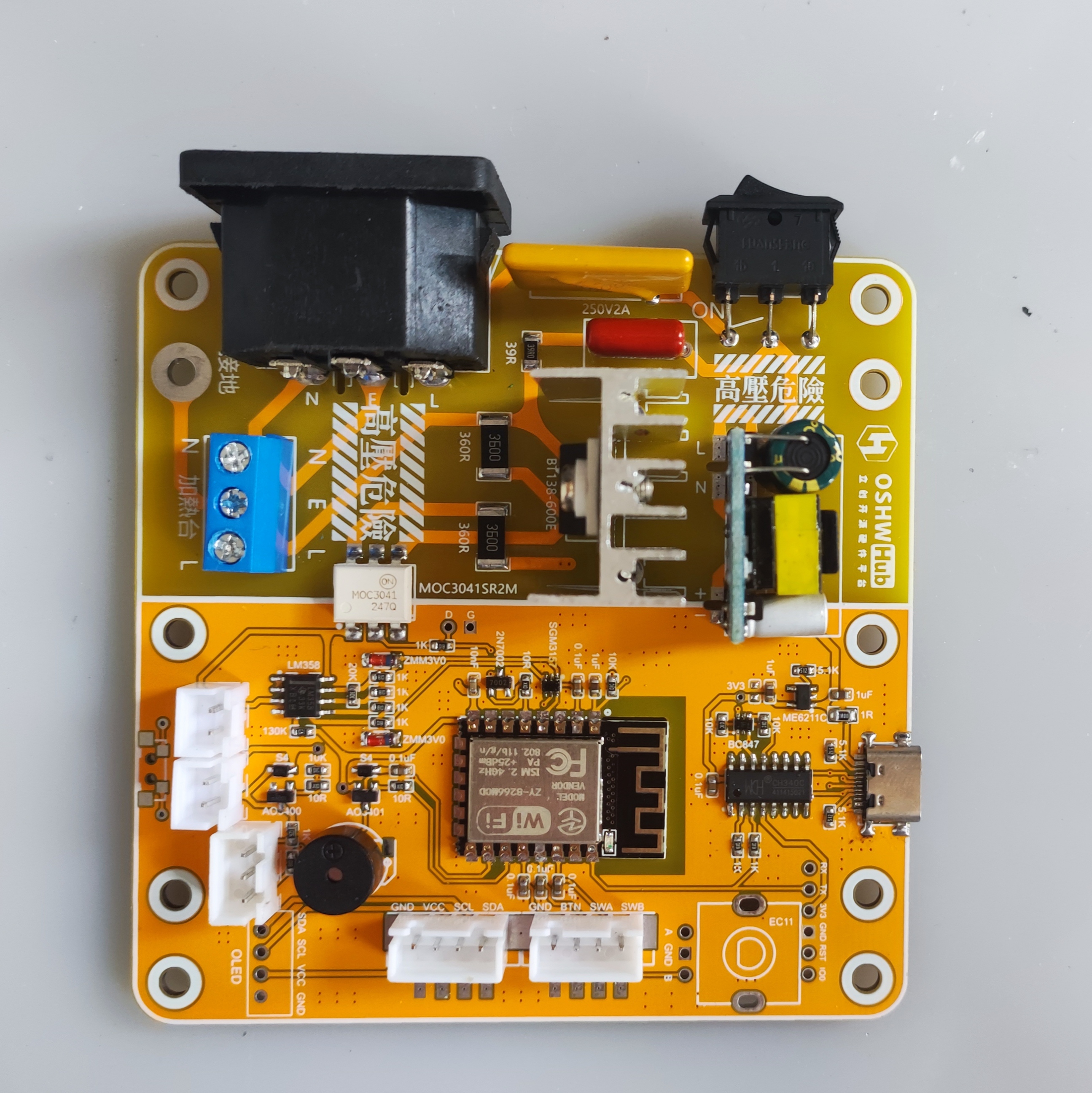
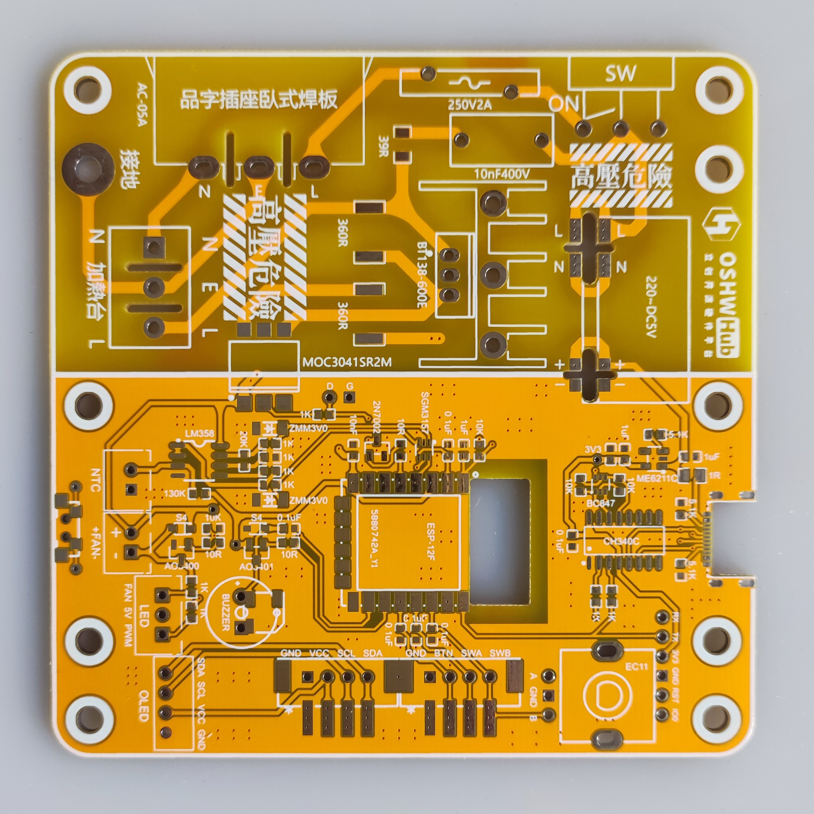
PCB Part - Motherboard:
The motherboard's AC power section remained unchanged; only the low-voltage section was modified.
Both CC pins of the Type-C port have been fitted with 5.1K resistors to ensure compatibility with fast charging cables (the original had the two CC pins shorted, which caused issues with Type-C cables with chips). The resistor and capacitor
packages are now standardized to 0603.
The antenna section of the ESP-8266 main controller has been recessed, theoretically resulting in a stronger Wi-Fi signal.
The original screen and encoder were difficult to plug in, so they have been modified to be compatible with standard XH2.54 straight-through and right-angle connectors, and also compatible with the original.
The original fan microswitch button was not very useful, so a side button with a different package was used (the circuit is disconnected, so soldering is not required, and it is slightly misaligned with the outer casing button).
The original SGM2028 LDO chip has been replaced with ME6211C33M5G-N (C7 10uF is optional), which is also compatible with the original SGM2028, RT9013-33GB, etc., and the circuitry is basically the same; I just prefer using the ME6211C.
Pull-down resistors R28 (IO12-SDA) and R29 (IO13-SCL) have been added (these two resistors are added later and do not need to be soldered). A
10K pull-down resistor has been added to pin IO14 to correct a potential issue of automatic heating upon power-on.
The original fan LED indicator has been replaced with a dual-color LED: green for fan operation and red for heating (which will flash according to the heating PWM status).
A buzzer has been added to provide beeping indications for power-on, heating start, and heating stop.
The original LM358P op-amp pinout has been changed to a surface-mount package, model LM358DR.
Due to modifications to several I/O ports, it is incompatible with the original firmware, but it will normally be updated synchronously with the original firmware.
PCB section - middle and upper heat insulation boards:
the two middle holes (two of which connect to the base plate) have had their original pads replaced with slots without metal connections to reduce heat transfer to the motherboard. The upper heating plate's hole positions are based on the Deer Fairy 400W heating plate (70*120mm), but have been changed to an oblong shape to ensure compatibility with other boards on the market that have the same dimensions but slightly different hole positions.
A new PCB for the display cover has been added .
The original project includes a BOM with a purchase link; the link for replacement is:
Replace the original LM358P with LM358DR. Uxin
has added a passive buzzer, compatible with both through-hole and surface-mount types. The through-hole size is 9*4mm (4.2mm is also acceptable), and the surface-mount size is 5*5mm (5020).
A PMOS AO3401 has been added to the buzzer circuit (note that this is AO3401, not AO3400; be careful to distinguish it from the fan circuit during soldering). Uxin
has replaced the original fan LED with a 3mm dual-color LED common anode (color can be chosen according to personal preference). Uxin
has replaced the original SGM2028 with ME6211C33M5G-N (optional). Uxin
has replaced the original 1N4148 diode with a smaller packaged 1N5819WS (S4).
The XH2.54 sockets used in the Uxin display, encoder, fan, and NTC have all been changed to through-hole type (compatible with the original surface-mount type). A new 3P socket for dual-color LEDs has been added. Uxin (this link includes 2P, 3P, and 4P)
has also made these changes compatible with the original casing
. Firmware modifications:
Based on changes in the hardware IO pins, the relevant IO definitions have been modified
for power-on start, heating start, and buzzer reminders on shutdown. The fan now
requires manual shutdown when manually started at room temperature.
A fan activity icon has been added.
Other minor optimizations are also
included. The revised firmware is in the attachment. To obtain the modified source code, please obtain permission from the original author (Qifan Kechuang) before the source code can be provided (the actual changes in the revised source code are minimal).
For more information, please refer to the original project's

display cover.

VID_20230824_110409.mp4
Modified firmware - 20230825.bin
Gerber_PCB_motherboard_v2.2.zip
Gerber_Middle Layer Insulation_v2.2.zip
Gerber_Upper Insulation Panel_400W_B_v2.2.zip
P Modified Source Code - 20230818-163.zip
90803
Router Uninterruptible Power Supply (UPS)
The router uses a UPS (Uninterruptible Power Supply) with a CN3006 for battery charging, a BM3451 for battery protection, a SY8368 for battery step-down output, an ESP32 for control, and an INA3221 for current sampling.
Project Overview:
This open-source project aims to design and implement an uninterruptible power management system (UPS) for routers, suitable for various application scenarios, including home automation, industrial control, and portable devices. The system integrates multiple functional modules, covering all key components from power input and battery management to output control, aiming to provide a stable and reliable power supply while ensuring the safe and long-term operation of devices.
Key Features and Components:
Power Input and Conversion:
A CN3306 boost converter chip is used to boost the 12V input voltage to 18V for charging a 5-cell lithium iron phosphate battery. A
SY8386 buck converter chip is used to stabilize the battery's 18V output to 12V, meeting the device's stable voltage requirements.
Battery Management and Protection:
An integrated BM3451 chip provides battery protection functions, including overcharge, over-discharge, and overcurrent protection, as well as equalization management of battery cells, ensuring battery safety and lifespan.
Multiple Voltage Outputs:
A TPS54302 chip steps down the 18V output from the battery to 5V, adapting to the voltage requirements of different devices and ensuring stable operation of all parts of the system.
The 1117 chip enables a 5V to 3.3V power supply to the ESP32.
Remote control and monitoring:
The integrated ESP32 microcontroller connects to the Home Assistant platform via Wi-Fi, enabling remote control, real-time monitoring, and data feedback, enhancing system intelligence and user experience.
Current monitoring and management:
The INA3221 chip monitors the current of various system components in real time, helping users understand energy consumption and optimize system efficiency.
Output management and protection:
Utilizing the LTC4412 ideal diode for output management ensures seamless switching between battery and external power, effectively protecting the circuit from reverse voltage and current surges.
NMOS and relays (added due to limited understanding of MOS management; final decision to be made after testing) provide overall output control.
Environmental monitoring:
Integrated temperature and humidity sensors and a cooling fan monitor ambient temperature and humidity, automatically adjusting the system fan to maintain safe operating temperature ranges.
Program platform:
Arduino
code and compiled firmware are attached.
Usage:
If unable to connect to Wi-Fi or MQTT, press and hold the button during startup to clear stored information.


petal_20240902_160349.mp4
ddd.ino
UPS-cs.ino.bin
PDF_Router Uninterruptible Power Supply UPS.zip
Altium Router Uninterruptible Power Supply (UPS).zip
PADS_Router Uninterruptible Power Supply UPS.zip
BOM_Router Uninterruptible Power Supply UPS.xlsx
90805
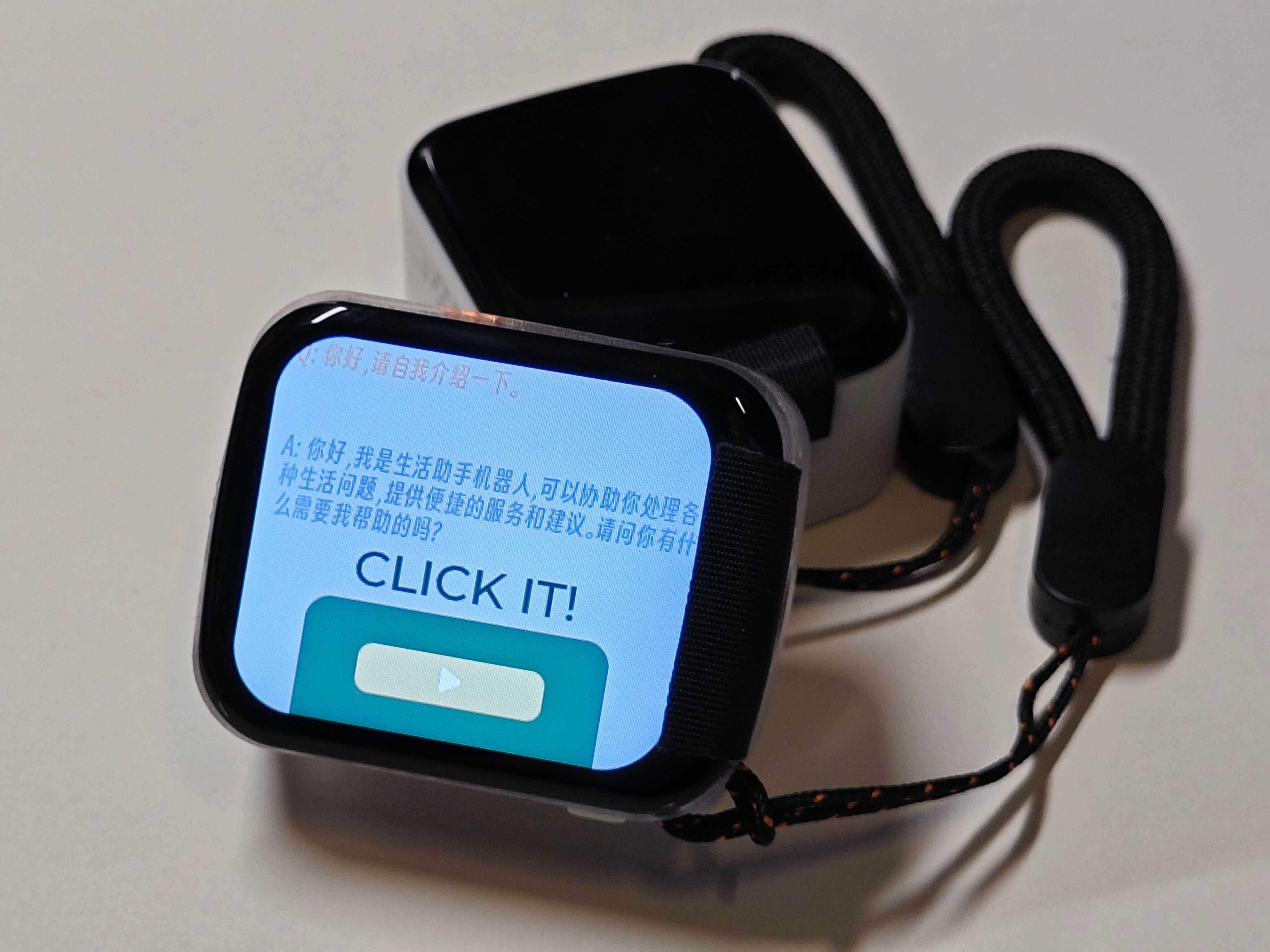
【EasyGPS】GPS locator based on ESP32S3
GPS locator based on ESP32S3
【EASY-GPS】
This project is based on: X-TRACK & CHAPPIE.
Author: kkl.
Video introduction: https://www.bilibili.com/video/BV1M44219745/
Github: https://github.com/ZhangKeLiang0627/EasyGPS


Hardware
configuration: Main controller: ESP32S3R8
; Screen: ST7789V 1.69-inch SPI interface 240x280 resolution;
Storage: Micro SD CARD 32GB + W25Q128JVPIQ;
Input device: Capacitive touch;
RTC: BM8563EMA;
IMU: MPU6050;
MAG: QMC5883L
; ENV: BMP280;
MIC: MSM261D4030H1CPM
; GPS: ATGM332H;
Battery: Li-ion 3.7V 603030 600mAh
; Power management: SGM4056 + SGM6036
casing: 3D printing
capability
supported; all native features of the X-TRACK project
supported; Bluetooth keyboard and mouse
supported; voice-activated smart assistant supported;
four-hour battery life (continuous operation, always-on screen)
. To be continued...
PDF_【EasyGPS】GPS Locator Based on ESP32S3.zip
Altium_【EasyGPS】GPS Locator Based on ESP32S3.zip
PADS_【EasyGPS】GPS Locator Based on ESP32S3.zip
BOM_【EasyGPS】GPS Locator Based on ESP32S3.xlsx
90806
AXP2101 & TG28 [Full-featured Professional Power Management Modules]
(Crowdfunding completed) Professional power management module, easy to replicate, with comprehensive documentation, modular design, full-function verification, exceptional cost-effectiveness, and ample chip supply.
AXP2101-PMIC
AXP2101 Power Management IC (AXP2101 power management chip)
Important Update 2024.8.19:
From now on, the AXP2101 chip is officially divided into two versions with different names. Original factory customized version (TG28) and Allwinner chip-compatible voltage version (AXP2101) are available.
The actual hardware and peripherals of AXP2101 and TG28 are identical, only the silkscreen is different.
Important Update 2024.3.21:
Crowdfunding customization of 2101 is complete. The customized voltage and timing are now announced as follows (see the attached Crowdfunding Customized Voltage AXP2101.PDF for detailed customization form).
Chip price: ¥10/pcs, group members: ¥8/pcs (limited time offer until 5 months). Bulk discounts available.
AXP2101 Development Materials (Public Version).rar
My ported IDF example.rar
AXP2101 Data Package 20240109 (Public Version).zip
Crowdfunding Custom Voltage AXP2101.pdf
TG28 Data Package 2024.zip
PDF_AXP2101&TG28 [Full-featured Professional Power Management Module].zip
Altium_AXP2101&TG28 [Full-featured Professional Power Management Module].zip
PADS_AXP2101&TG28 [Full-featured Professional Power Management Module].zip
BOM_AXP2101&TG28 [Full-featured Professional Power Management Module].xlsx
90807
EMC/EMI probe low-noise amplifier
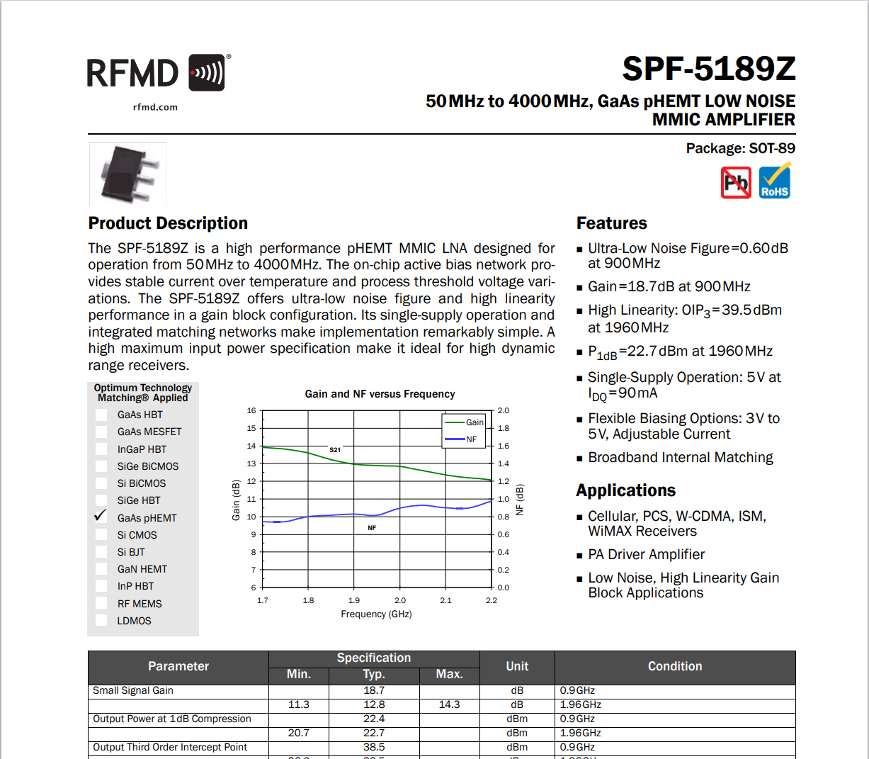
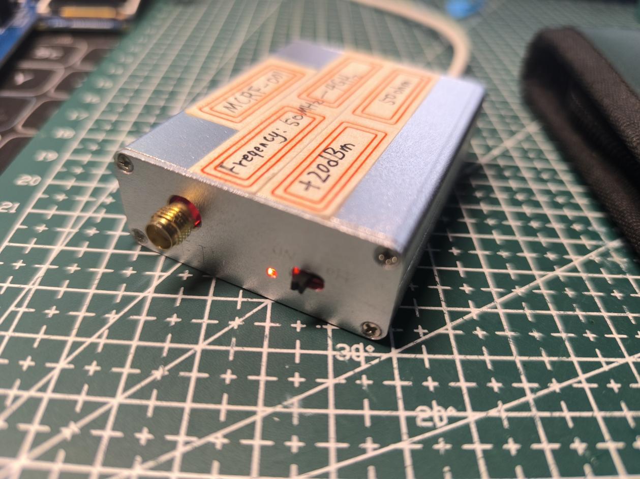
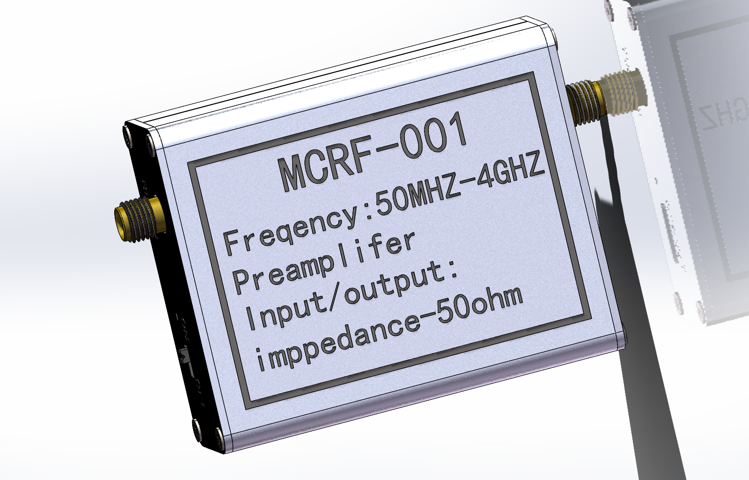
0.05~4GHz, 20dB gain, self-powered low-noise amplifier for EMC/EMI electromagnetic radiation leakage detection, used for front-end detection amplification of EMC/EMI electromagnetic leakage in electronic products, and signal processing amplification in radio frequency front-ends. Comes with a custom-made probe.
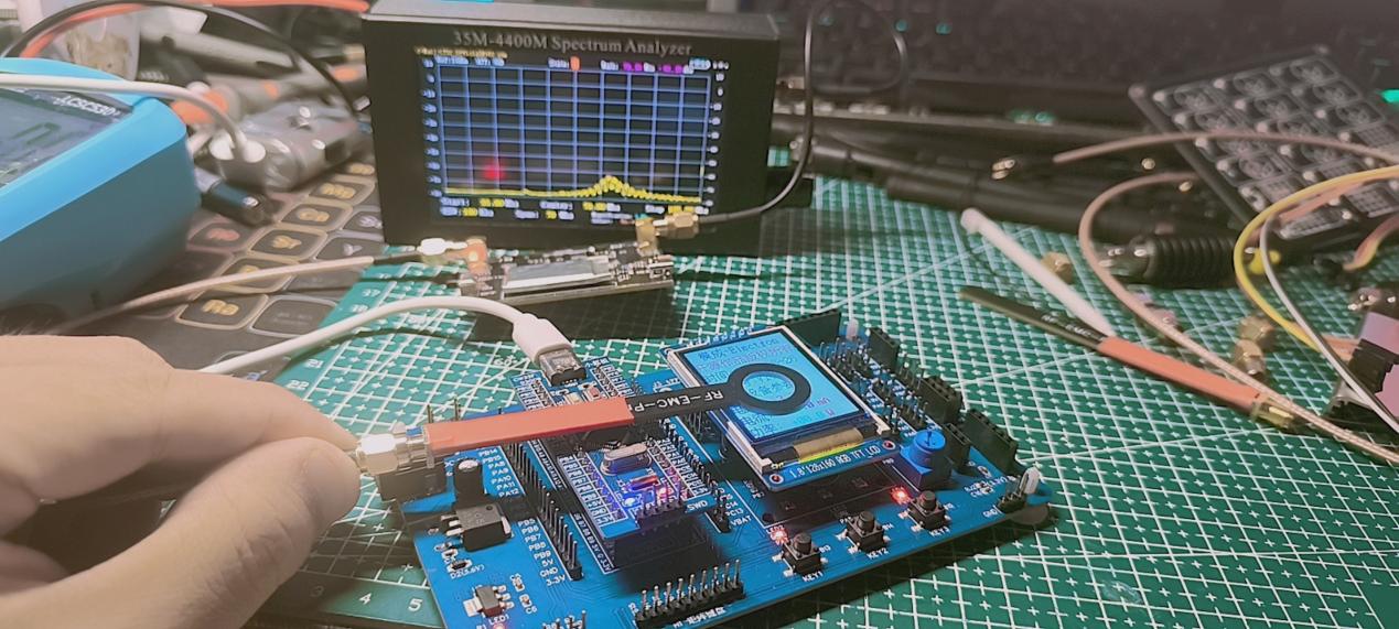
This EMC/EMI electromagnetic radiation amplifier is used for electromagnetic radiation noise detection and amplification in electronic products. It serves as a pre-amplifier for RF power amplifiers, with a built-in power supply providing independent power for up to 3 hours of continuous operation, or it can be externally powered. The input connects to a probe, and the output signal can be directly fed into a spectrum analyzer or RF power amplifier.
Open source protocol: CC-BY-NC-SA-4.0.
Parameters:
Frequency range: 0.05GHz-4GHz;
Amplification gain: 20dB (two-stage amplification)
; Impedance: 50Ω; Power
supply: 5V-1A;
Battery capacity: 250mAh (3 hours of continuous operation on a full charge)
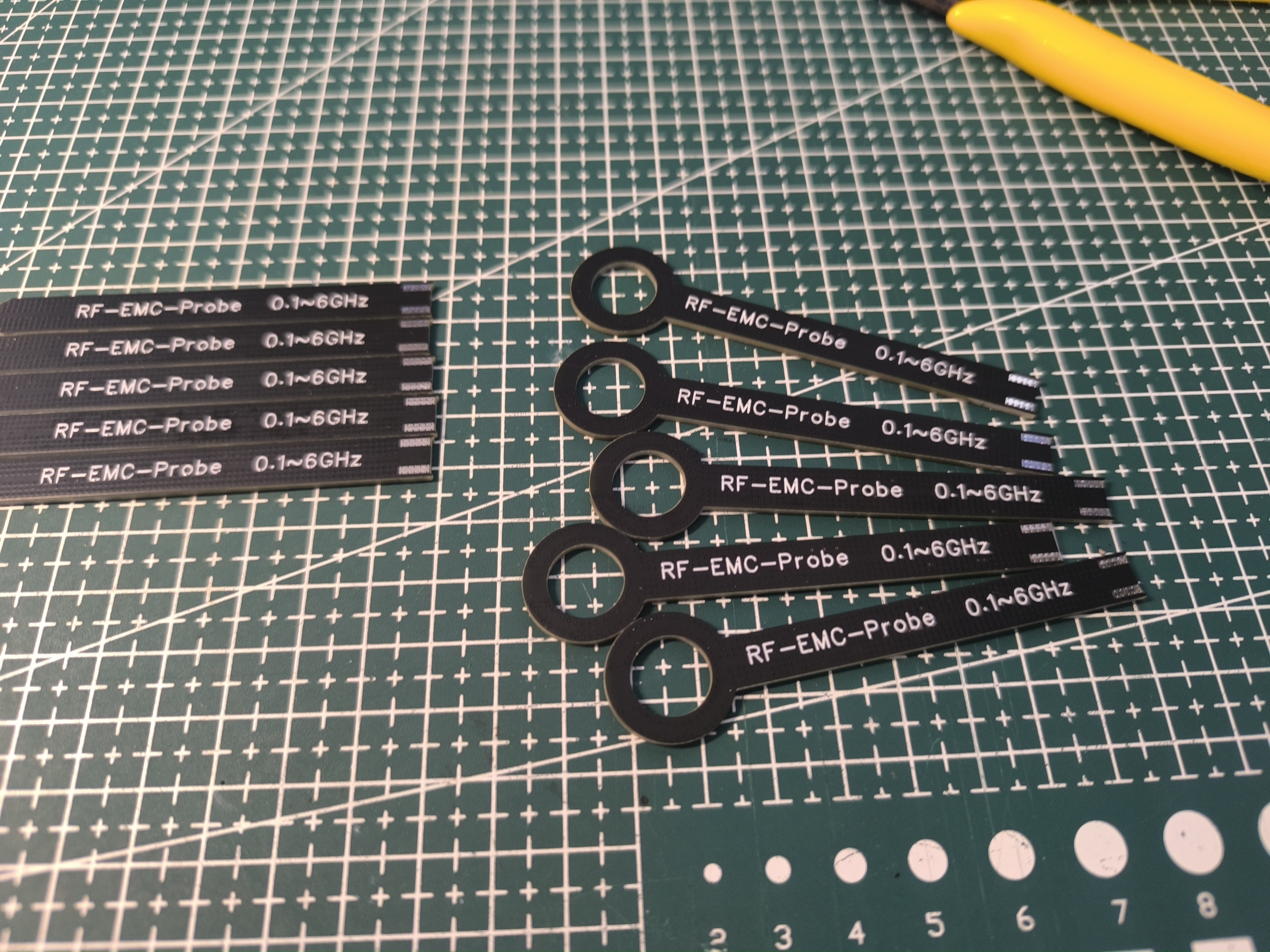
; Probe: 50Ω impedance;
RF section low-noise amplifier chip: SPF-5189Z;
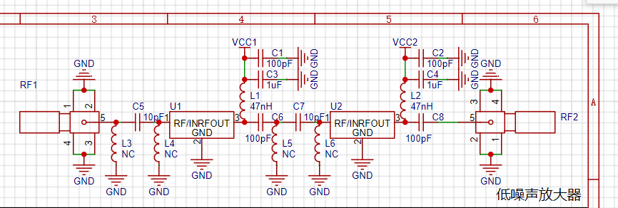
Two-stage amplification, 10dB per stage, 20dB for both stages; Vector
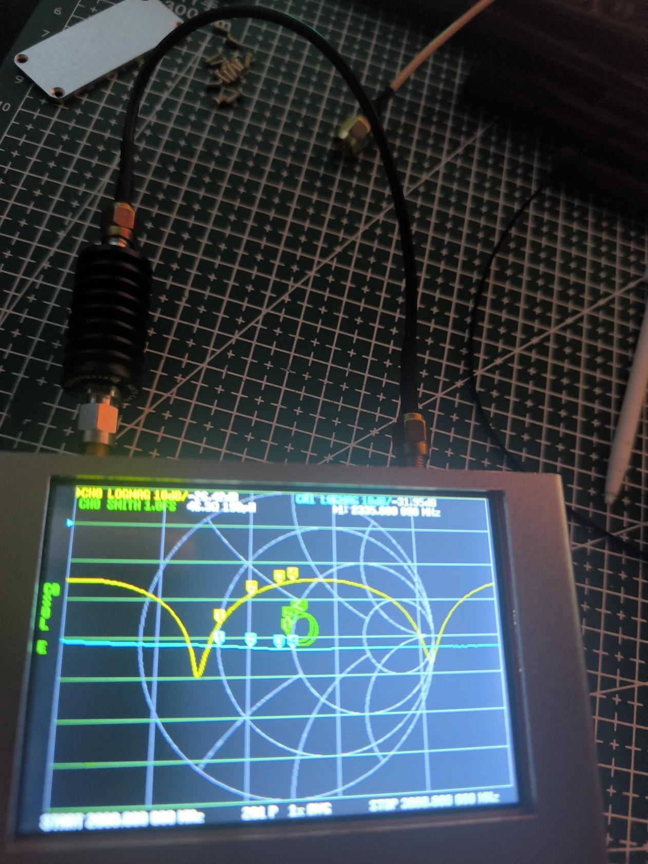
grid amplification gain test: A -30dB gain attenuator is inserted in series in the RF circuit, interface loss has been calibrated, line loss is approximately 1.95dB;
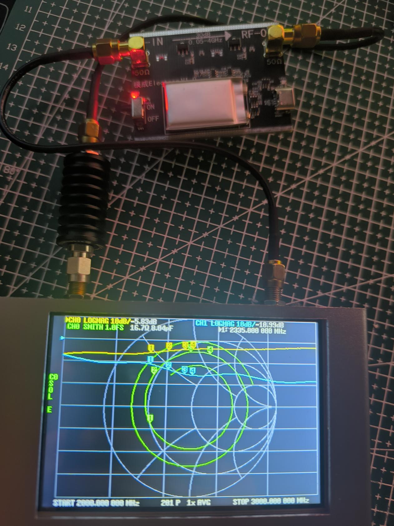
Vector grid amplification gain test: A low-noise gain amplifier is inserted in series, total attenuation is 10.99dB = 30dB - 20dB.
(Note: The charge pump and low-noise amplifier chip will generate heat during operation. Without proper cooling, the charge pump will overheat and trigger overheat protection, reducing the amplification gain of the low-noise amplifier.)
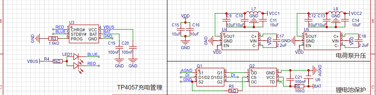
The power supply uses a lithium battery, with the charge pump boosting voltage to reduce power supply noise. The charge pump uses the HX4002, and the
charging management uses the small-size TP4057 charging management chip. (Note: The charge pump and low-noise amplifier chip will generate heat during operation. Without proper cooling, the charge pump will overheat and trigger overheat protection.)

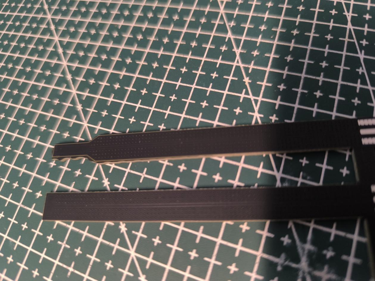
The probe is a panel; after prototyping, it needs to be disassembled and the cross-section ground. Different probes are suitable for different detection areas.
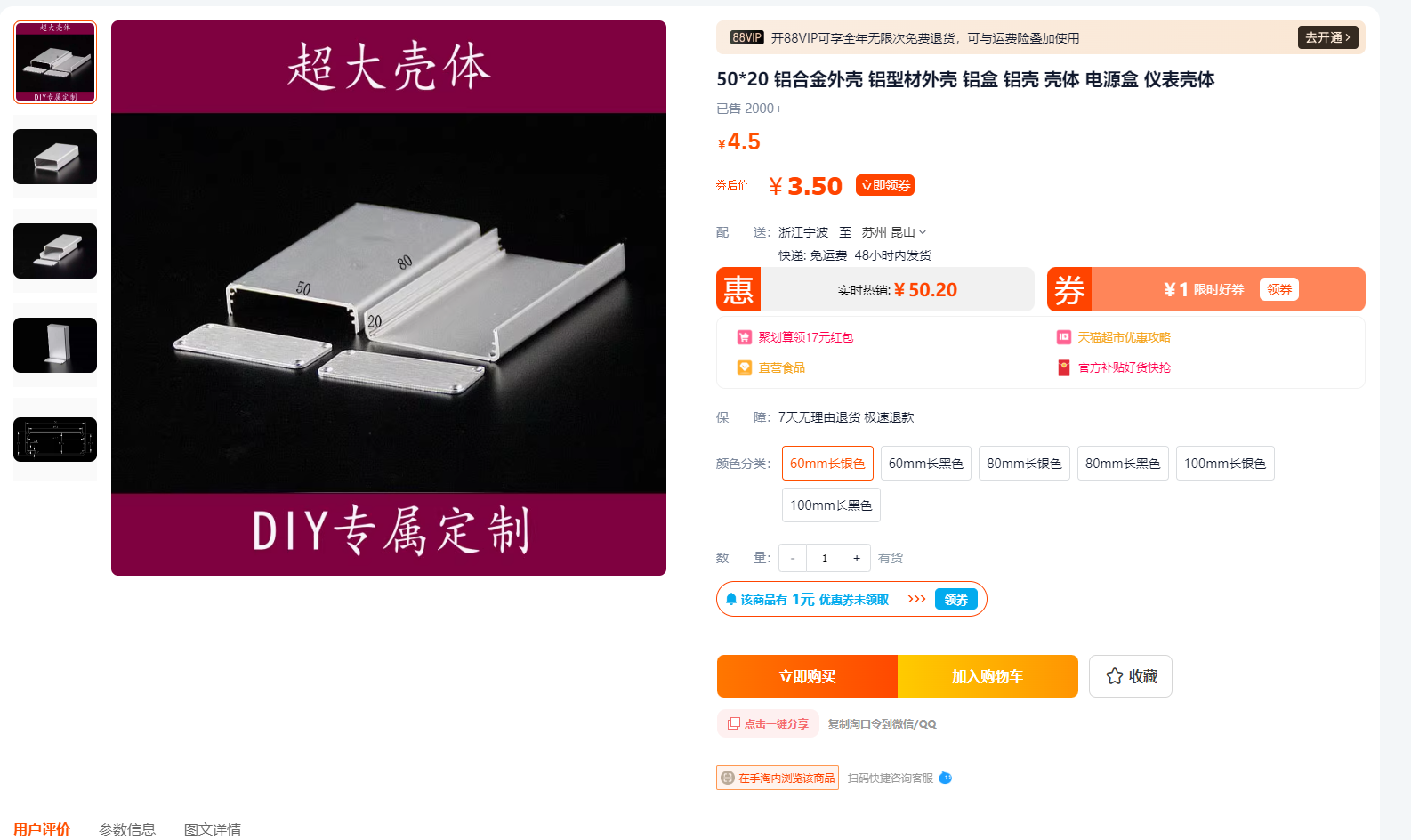
The housing is a lightweight aluminum alloy. For cost reasons, a pre-made housing was chosen, but this housing has gaps during assembly. To achieve lower noise and avoid external interference, a CNC-machined housing is recommended.
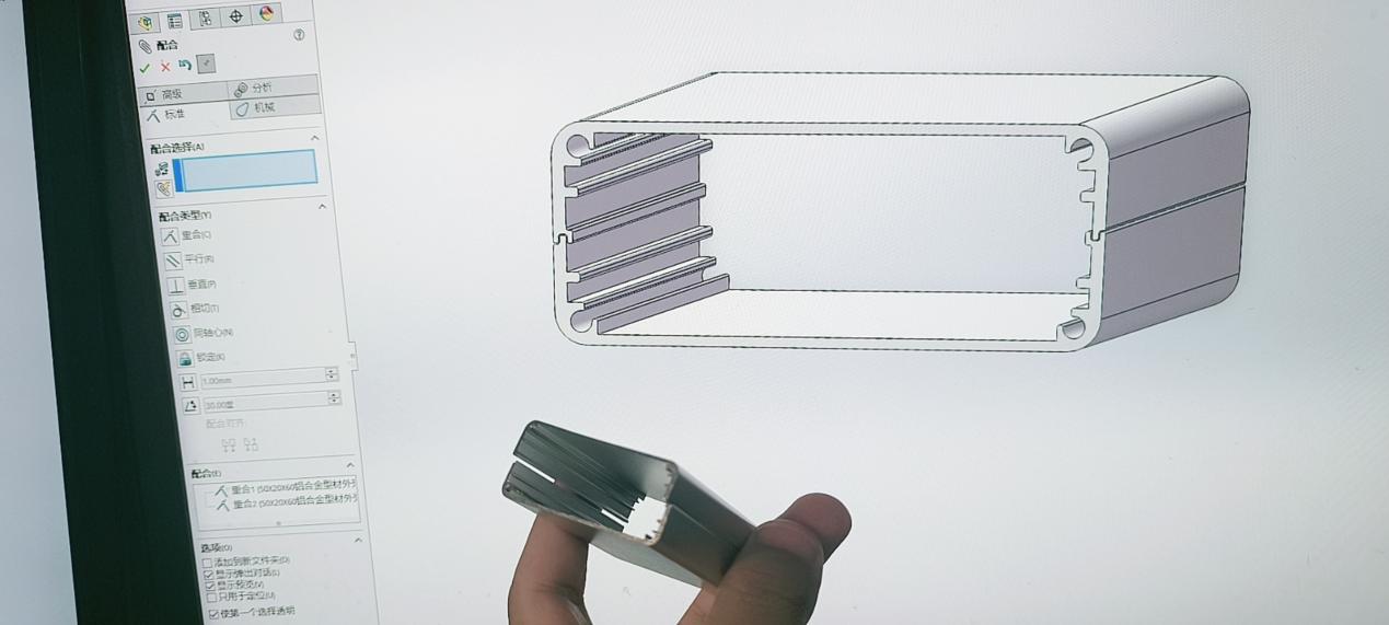
Processing parameters: CAD drawings; please send the drawings to the manufacturer for processing.
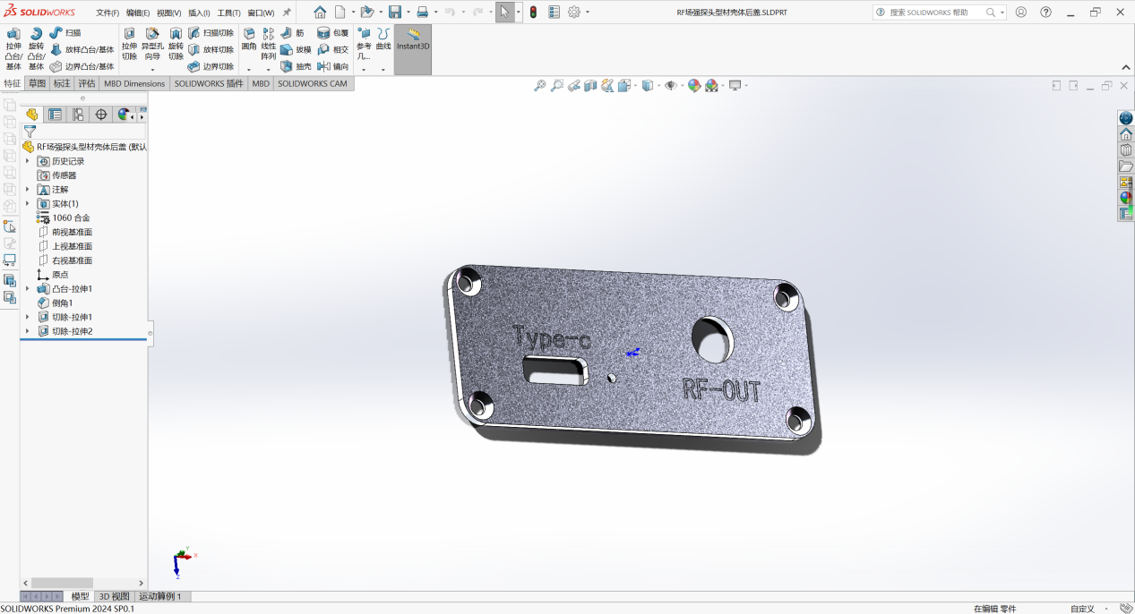
Front panel:

Rear panel:

Remarks: (Laser marking is recommended for the font parts)
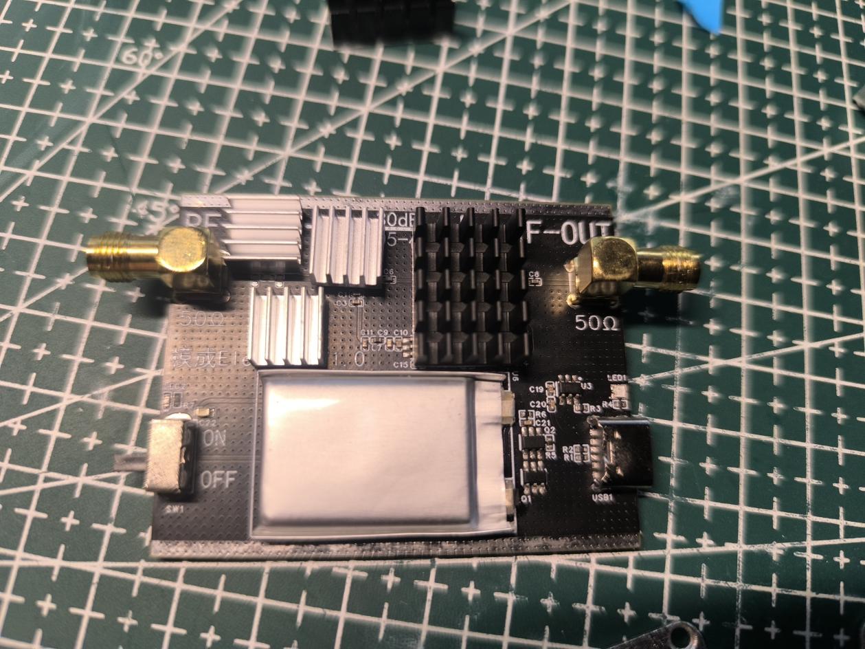
PCB assembly effect:

Heat sink added to the heat-generating parts:
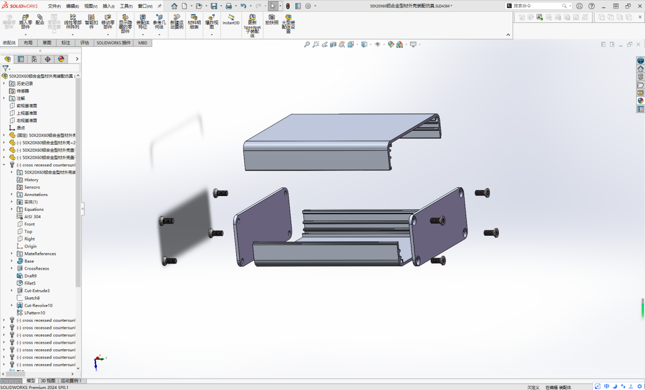
Complete component drawing:
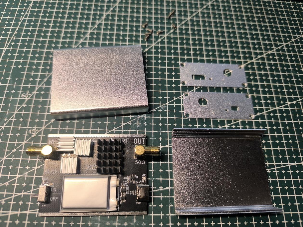
Assembled product drawing:
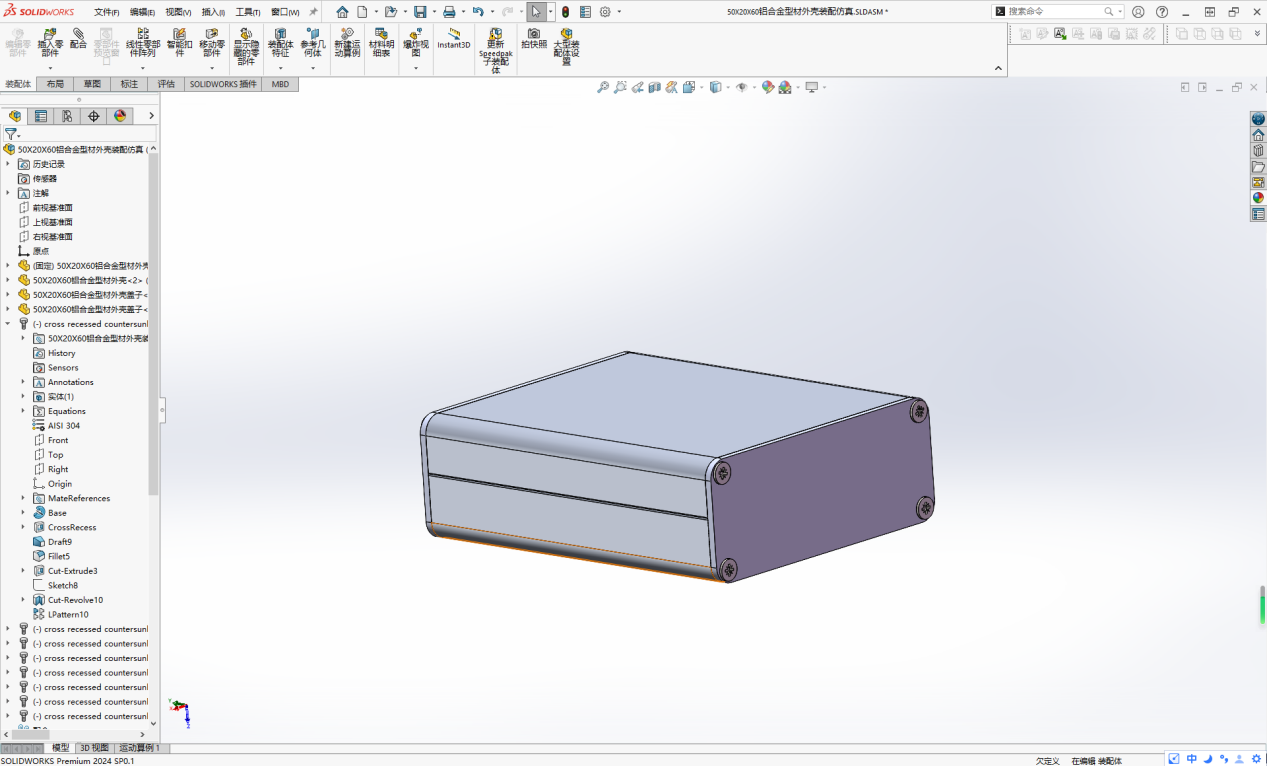
Simulation drawing:

CAD processing images and CNC processing files for the outer shell are attached.
Test video: The interference source is a 0.05~4GHz 20dB gain buzzer at the bottom of the microcontroller development board.
It is a self-powered low-noise amplifier for EMC/EMI electromagnetic leakage detection in electronic products. It comes with a self-made probe.
Shell processing files.zip
VID_20240723_230453.mp4
PDF_EMC-EMI probe low-noise amplifier.zip
Altium_EMC_EMI probe low-noise amplifier.zip
PADS_EMC_EMI probe low-noise amplifier.zip
BOM_EMC_EMI probe low-noise amplifier.xlsx
90808
[Azure Archives] Jerry DSP Bluetooth TWS Color Silkscreen Module
Using JL AC7916A as a Bluetooth module board with DSP, Bluetooth, and TWS functions.
Considering the copyright issues associated with color silkscreen printing, as well as the potential for resale and commercial use, I will no longer provide complete designs. I will only provide copyright-free backgrounds or complete designs with watermarks. If you require color silkscreen printing, you will need to find the images yourself, assemble them, and then place them on the PCB. Alternatively, you can obtain authorization from the relevant copyright holders or companies, submit screenshots of the authorization to me, and I can provide the original source files.

1. Introduction:
This Bluetooth module, using the JL AC7916A chip for analog audio input, features DSP, Bluetooth, and TWS functions. It's a small, color-screened PCB

with a built-in DSP that supports online EQ adjustment (default 10 bands, can be increased to 30 bands with a configuration file, but this consumes more FLASH).
The built-in DSP supports DRC (LowBand DRC, HighBand DRC, full-band DRC to be added later). It supports
Bluetooth playback (BLE V5.3, supports SBC)
, TWS interconnection
, AUX sampling: 48kHz sampling rate (2 channels )
, AUX playback: 48kHz ,
UAC playback (USB sound card)
, USB playback (supports AAC, ADPCM, AMR, APE, DTS, FLAC, M4A, MP1, MP2, MP3, OPUS, SPX, WAV, WMA, PCM audio decoding formats), and
TF card playback (single-line).
There are actually many similar chips, such as the Mountainview BP1048, but they are not open-source.
This project is based on
the JL AC7916A Bluetooth + WIFI dual-core development board from Jieli
. Power management, battery, amplifier, OLED, DAC, and UART functions have been removed,
retaining only analog input/output, buttons, USB, SD card, and basic power supply.
Official development documentation (SDK 1.0.3, version 1.1.0 or higher recommended):
https://doc.zh-jieli.com/AC79/zh-cn/release_v1.0.3/board_description/board_overview/index.html
Official schematic: Official developer version purchase link:
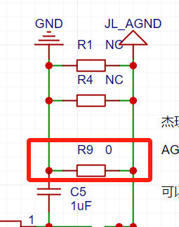
https://gitee.com/Jieli-Tech/fw-AC79_AIoT_SDK/tree/release/AC79NN_SDK_V1.0.3/doc/datasheet/AC791N%E8%A7%84%E6%A0%BC%E4%B9%A6/schematic/JL_AC79_DevKitBoard (The following is an attachment: https://item.taobao.com/item.htm?spm=a1z10.1-cs.w4004-22883854875.30.504d246b7hM503&id=668602916268&mt=) The FW and UFW flashing files, as well as my personal EQ tuning file, have been uploaded; see attachments. Additionally, this JL chip has a low-noise issue; the audio GND and power supply GND should not be on the same group. For example, if your audio output is from your computer motherboard, don't use the computer's USB power supply. Use a power adapter from a different location, a battery, or a power bank. However, if AGND and GND are not connected, when there is no audio input, the output AGND will float, resulting in significant noise. You can replace the 0-ohm resistor connecting GND and AGND with a 75-ohm resistor. This will reduce noise to almost inaudible levels without causing excessive floating noise from AGND when there is no input. 2. See the attached PSD file for color silkscreen printing . Copyright: YOSTAR PICTURES PIXIV. Used by: 111148581 아니아나 (Aniana) 111636787 ACh
EQ.bin
jl_isd.fw
jl_isd.ufw
Top layer color silkscreen.psd
Underlying color silkscreen.psd
PDF_【Azure Archives】Jerry DSP Bluetooth TWS Color Silkscreen Module.zip
Altium_【Azure Archives】Jerry DSP Bluetooth TWS Color Silkscreen Module.zip
PADS_【Azure Archives】Jerry DSP Bluetooth TWS Color Silkscreen Module.zip
BOM_【Azure Archives】Jerry DSP Bluetooth TWS Color Silkscreen Module.xlsx
90809
CyberGun (Smart Gun)
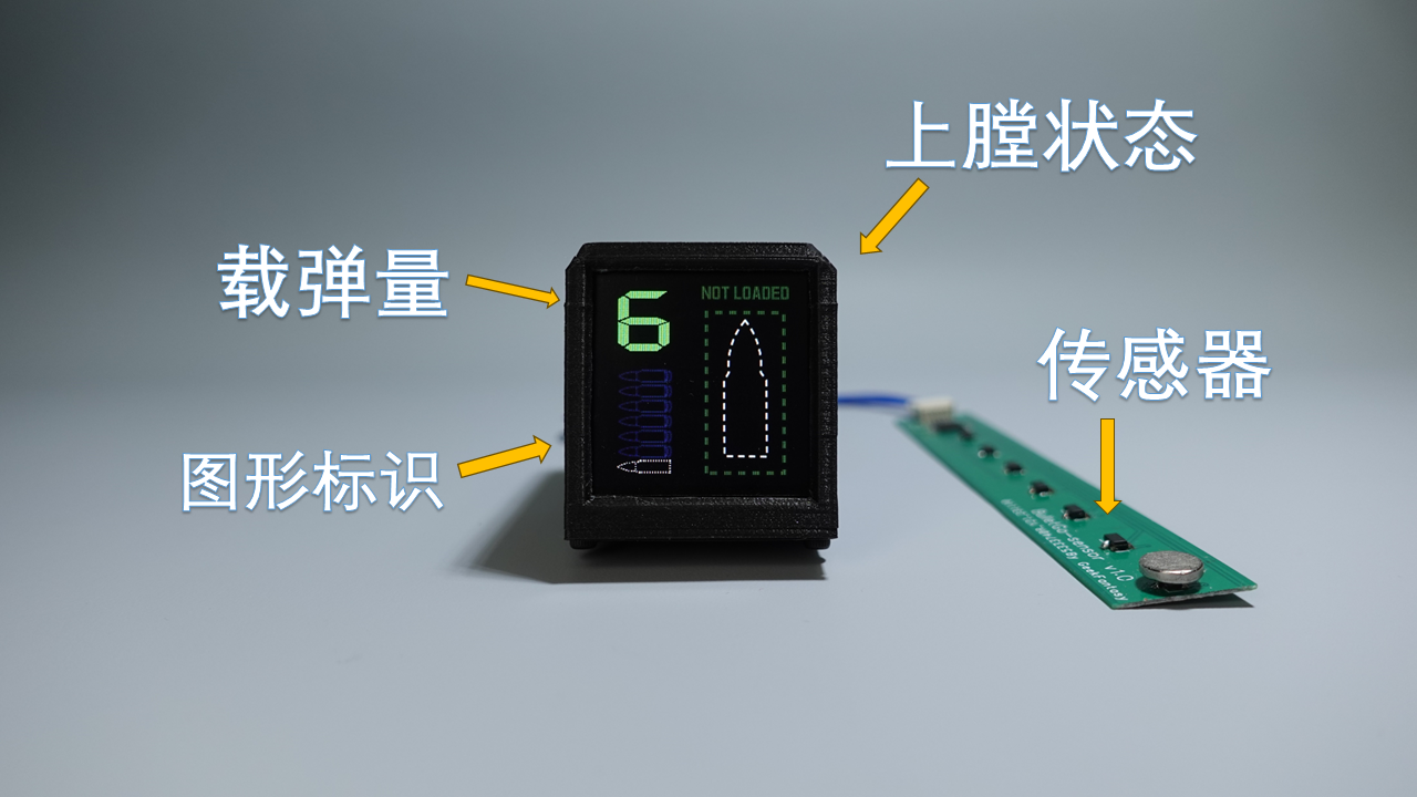
The Gecko 2.0 soft-shell launcher has undergone an intelligent upgrade, with the development of a device to display ammunition load, chamber status, and provide training on gun stability.
Project Description:
The primary objective of this project is to intelligently upgrade a soft-ball (sponge-like) launcher (Senbailong Gecko 2.0). A device based on an ESP32-Pico-D4 microcontroller is installed on the launcher, featuring a 1.33-inch TFT screen, an integrated IMU (MPU6050), and eight Hall effect sensors. The IMU uses motion sensing to interact with the system, while the Hall effect sensors, in conjunction with magnets, detect ammunition load and chamber status. The ESP32's integrated Bluetooth and Wi-Fi allow for interaction with other systems and data reporting.
(Bilibili video: I made a smart gun and developed a matching smart application, something you probably can't even play in games_Bilibili_bilibili)
Features include: ammunition load detection, chamber and firing detection, shooting stability detection, gun holding stability training, and motion monitoring.
Application

Switching: The device only has a top button and does not use a touchscreen; therefore, it relies on the device's IMU to sense the device's status for operation. Switching applications requires tilting the launcher left or right, swiping the screen once for the preset application, straightening the screen, and pressing the button on the device to enter the application.
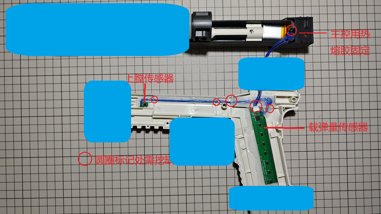
Ammunition Load Display & Loading/Firing Status Detection -- Upon entering the application, the left side of the screen displays the ammunition load and indicator, while the right side displays the loading and firing status. After loading a magazine, the device uses an ammunition load detection circuit to check if a magazine is loaded; if so, it checks the ammunition load again. Simultaneously, the device also detects the loading status. A preset animation effect is displayed when switching between loading and firing statuses. Green indicates no loading, and red indicates a loaded magazine.

Shooting Stability Detection -- This application displays the range of horizontal and vertical direction changes of the device within one second before and after trigger firing, using a two-axis graph to show shooting stability. The flatter the graph curve, the more stable the gun is when firing. This application only displays data; data collection is completed on the ammunition load display interface. The device records the last 5 shots, numbered 1-5, with 1 representing the most recent shot.

Gun Stability Training -- This application is for training purposes. Upon entering the application, a 3-second countdown will occur. After the countdown ends, a target and a green or red dot will be displayed on the screen. The dot changes position according to the launcher's direction. When the dot is near the target's center, it's green, indicating stable aiming; when it turns red, it means the launcher is deviating from its original direction. During training, you need to try to keep the dot centered on the target. The upper left corner of the screen displays the timer, and the upper right corner displays the real-time score. The longer you keep the dot centered, the higher the score, and vice versa.
Motion Status Monitoring – After entering the application, the device starts a Wi-Fi server, and the device screen displays the server address. After connecting to this address with a computer, running the computer-side script will display a real-time 3-axis acceleration curve. The acceleration curve can be used to determine the motion status of the person holding the launcher.
Project Progress
Hardware: Completed, 3D shell files are attached.
Software: Completed Source Code: GeekFantasy/BulletGo (github.com)
Design Principles
The entire project consists of three parts: the main control board, the sensor board, and the programming board, as shown in the diagram below. The main control board integrates an MCU, MPU6050, LCD, and battery management chip, running the main control program. The sensor board integrates an 8-bit GPIO expansion chip, connected to the motherboard via IIC. The eight GPIOs are connected to eight Hall effect sensors for detecting bullet count and chamber status. The programming board integrates a serial port chip and an automatic programming circuit for programming the main control board and for serial communication via a UART bus.

Circuit
Principle:
The main control chip is the ESP32-PICO-D4, a system-in-package (SiP) module based on the ESP32, providing complete Wi-Fi and Bluetooth® functionality. This module has dimensions of only 7mm × 7mm × 0.94mm, occupying a minimal PCB area, and integrates a 4MB Serial Peripheral Interface (SPI) flash. Therefore, the peripheral circuitry can be very simple, allowing for the integration of more components within a relatively small space. The CP-RX/TX pins connect to the serial port chip for logging and programming. The IO0 and EN pins are connected to the programming board and are used to control the chip's switching between programming and LOG modes. LCD-BL/DC/MOSI/SCK/RES control the LCD display driven by the ST7789. GPIO35 connects to a single button used to enter and exit the application. SEN-INT/SCL/SDA connects to the GPIO expansion chip on the sensor board, which can obtain the ammunition load and detect whether it is chambered. MPU-INT/SCL/SDA communicates with the MPU6050 for motion-sensing interaction in the user application. The

ammunition load and chamber status detection circuit
is located on the sensor board, mounted on the side of the magazine in the launcher. To reduce the number of lines with the main control board, an I2C interface GPIO expansion chip, NXP's PCA9554PW,118, is used to expand 8 GPIOs, each connected to one of 8 Hall sensors. Seven of these Hall sensors are aligned with the magazine load positions 0-6. A circular magnet is fixed on the magazine feed plate to trigger the Hall sensors at different positions. As the ammunition load decreases, the magnets move upwards sequentially, triggering Hall effect sensors at different positions. The PCA9554W reports the GPIO status, allowing the main controller to acquire the ammunition load. Another Hall effect sensor, located at the bolt catch, senses the magnet mounted on the bolt to determine if it is chambered.

Due
to limited space on the main control board, the programming board is handled independently, primarily for program burning and serial communication. A CP2102, along with two transistors, is used to achieve automatic program burning and automatic switching between LOG modes.

Assembly steps:
1. Assemble and test the hardware components as shown in the diagram


. 2. Fix each hardware component to the disassembled transmitter according to the wiring diagram, using hot glue or other adhesives (the blue parts in the diagram are used to cover critical areas; otherwise, it will be recognized as a gun and cannot be uploaded).
3. Install the Hall effect sensor trigger magnets as shown in the diagram.

4. Reassemble the transmitter, test, and you're done.
Device Code:
Firmware code is developed based on the open-source project HoloCubic_AIO; ESP32 code (Arduino): GeekFantasy/BulletGo (github.com)
Materials and Assembly:
PCB: 3 circuit boards: Main_v2.1 (1.2mm thick), Prog_v2 (1.2mm thick), and Sensor_v2 (0.6mm thick or FPC).
Screen: 1.33-inch 240x240 LCD, ST7789 driver, soldered 12-pin bare screen (purchased from Taobao - Zhongjingyuan Electronics)
. Connection Cables: The 3 circuit boards are connected via interface terminals; the terminal connection cables need to be made by yourself and can be purchased from JLCPCB.
Battery: 3.7V lithium-ion battery, model-902030. 500mAh (Thickness: 9mm, Length: 30mm, Width: 20mm) - Please purchase separately (the one I previously purchased is no longer available).
Soft Egg Launcher: All devices need to be integrated into the Gecko 2.0 Soft Egg Launcher. You can purchase it yourself on Taobao by searching the keyword: Senbailong Gecko Launcher 2.0.
Main Control Shell: Needs to be printed separately; see attached model.
Firmware Burning:
1. Using IDE for programming: The program is developed using PlatformIO. You can download the program, compile it, and then directly program it.
2. Using ESP32 programming tool: To be provided later.
Notes:
When prototyping, please pay attention to the board thickness: Main_v2.1 1.2mm, Sensor_v2 0.6mm FR-4 board or use FPC (reinforcement is not required). Boards that are too thick will not be able to be installed.
Currently, the connection between the sensor and main control components is not specially treated, and the wiring harness will be exposed. Those who mind this can wait until a solution is available before replicating.
Reference projects:
Zhihui's HoloCubic (link),
ClimbSnail's HoloCubic_AIO (link)
CyberGun.mp4
Shell 3D file.zip
PDF_Smart Gun [CyberGun].zip
Altium_SmartGun[CyberGun].zip
PADS_Smart Gun[CyberGun].zip
BOM_Smart Gun[CyberGun].xlsx
90810
electronic


 京公网安备 11010802033920号

 1CIS068-29TT3M


