The circuit shown in Figure 1 measures peak and rms power at any RF frequency from 450 MHz to 6 GHz with a dynamic range of approximately 45 dB. The measurements are converted to a differential signal to eliminate noise and form a digital code at the output of the 12-bit SAR ADC via a serial interface and an integrated voltage reference. Perform a simple two-point calibration in the digital domain.
The ADL5502 is a mean response (true rms) power detector with a built-in envelope detector that can accurately measure the crest factor (CF) of modulated signals. It can be used in high frequency receiver and transmitter signal chains from 450 MHz to 6 GHz with envelope bandwidths in excess of 10 MHz. The peak hold feature allows short peaks in the envelope to be captured using a lower sampling rate ADC. The device's total power consumption is only 3 mA (3 V).
The ADA4891-4 is a high-speed, quad-channel, CMOS amplifier that combines high performance with low cost. Each amplifier consumes only 4.4 mA (3 V). The amplifier has single-supply capability and an input voltage range that extends to 300 mV below the negative supply rail. The rail-to-rail output stage allows the output to swing to within 50 mV of each supply rail to ensure maximum dynamic range. Low distortion and fast settling time make this device ideal for this application.
The AD7266 is a dual-channel, 12-bit, high-speed, low-power successive approximation ADC that operates from a single 2.7 V to 5.25 V supply and can sample at rates up to 2 MSPS. This device contains two ADCs, both preceded by a 3-channel multiplexer and a low-noise, wide-bandwidth sample-and-hold amplifier capable of handling input frequencies above 30 MHz. Power consumption is only 3 mA (3 V). In addition, a 2.5 V reference voltage source is built-in.
The circuit is powered by a +3.3 V single supply from the ADP121 , a low quiescent current, low dropout linear regulator that operates from a 2.3 V to 5.5 V supply with a maximum output current of 150 mA. The dropout voltage is only 135 mV when driving a 150 mA load. This low dropout feature not only improves efficiency, but also allows the device to operate over a wide input voltage range. Quiescent current is as low as 30 μA at full load, making the ADP121 ideal for use in battery-powered portable devices.
The ADP121 is available in output voltages ranging from 1.2 V to 3.3 V, and its performance is optimized for stable operation with a small 1 μF ceramic output capacitor. The ADP121 has excellent transient response performance and occupies an extremely small circuit board area. Short-circuit protection and thermal overload protection circuitry protect the device from damage under adverse conditions. Available in 5-pin TSOT and 4-pin, 0.4 mm pitch, halogen-free WLCSP packages, the ADP121 is the industry's smallest solution for a variety of portable applications.


The measured RF signal is applied to the ADL5502, and the 75 Ω termination resistor at the RF input is connected in parallel with the input impedance of the ADL5502 to provide 50 Ω broadband matching. More precise resistive or reactive matching is available for narrowband applications (see the "RF Input Interface" section of the ADL5502 data sheet).
The ADL5502's internal filter capacitor provides an average in the squared domain but retains a residual AC signal at the output. Peak-to-average ratio signals (such as W-CDMA or CDMA2000) can produce AC residual levels at the ADL5502 VRMS dc output. To reduce the impact of these low-frequency components on waveform formation, some additional filtering is required. The ADL5502's internal square-domain filter capacitor can be enhanced by connecting the CFLTR capacitor from Pin 1 (FLTR) to Pin 2 (VPOS). The AC residual level is further reduced by adding capacitance to the VRMS output. The internal 100 Ω output resistor, together with the added output capacitance, forms a low-pass filter, reducing output ripple at the VRMS output (see "Selecting a Squared Domain Filter" and "Output Low-Pass Filter" in the ADL5502 data sheet for more information part).
To measure the waveform peak, the control line (CNTL) must be temporarily set to logic high (reset mode >1 μs) and then returned to logic low (peak hold mode). This initializes the ADL5502 to a known state. When setting the device to measure peaks, peak hold mode should be toggled during which the input rms power and crest factor (CF) do not change.
If the ADL5502 is in peak hold mode and CF changes from high to low, or the input power changes from high to low, an erroneous peak measurement will be reported. The ADL5502 only reports the highest peak that occurs when peak hold mode is enabled and input power or CF is high. The PEAK output does not reflect the latest peak within the signal unless CNTL is reset.
The ADL5502 is capable of delivering approximately 3 mA of VRMS output current. The output current is supplied through the on-chip 100 Ω series resistor; therefore, any load resistance forms a voltage divider with this on-chip resistor. It is recommended to drive a highly resistive load with the ADL5502 VRMS output to maintain output swing. A snubber circuit is required if the application requires driving low-resistance loads (and where increased nominal conversion gain is required).
The PEAK output is designed to drive a 2 pF load. It is recommended to drive low capacitive loads with the ADL5502 PEAK output to achieve full output response time. The effect of larger capacitive loads is especially noticeable when tracking the envelope during falling transitions. When the envelope is in a falling transition, the load capacitance is discharged through the 1.9 kΩ on-chip load resistor. If a larger capacitive load cannot be avoided, the additional capacitance can be offset by connecting a shunt resistor at the PEAK output to ground, allowing for rapid discharge. This shunt resistor allows higher currents to flow through the ADL5502 and should not be lower than 500 Ω.
Typical measured performance characteristics of this circuit are shown in Figures 2 through 5.


The turn-on time and impulse response are significantly affected by the square-domain filter size ( FLTR ) and the output shunt capacitance connected to the VRMS output. Figure 6 (from the ADL5502 data sheet) shows a plot of the output response versus an RF pulse on the RFIN pin with a 0.1 μF output filter capacitor and no squared domain filter capacitor (C FLTR ). The falling edge is clearly related to the output shunt capacitance. .


To improve the enable and pulse response on the falling edges, place a resistor in parallel with the output shunt capacitor. The added resistor helps discharge the output filter capacitor. Although this method shortens the off-time, the added load resistor also attenuates the output (see the "Output Drive Capability" and "Buffering" sections of the ADL5502 data sheet). Figure 7 (from the ADL5502 data sheet) shows the improvement achieved by adding a 1 kΩ parallel resistor.


The RMS and PEAK outputs of the ADL5502 pass through a unity-gain buffer, which drives a cross-coupled stage that converts the single-ended output to a differential signal. The AD7266's +2.5 V internal reference (connected via the D CAP A and D CAP B pins) is routed through another unity gain buffer and voltage divider, which sets the network common mode voltage to +1.25 V. .
The AD7266 enables simultaneous sampling of the RMS and PEAK outputs and transmits data within a 1 μs response time. Data is provided over a single serial data line. Because slope and intercept vary from device to device, board-level calibration must be performed to achieve high accuracy. Generally speaking, calibration is performed by applying two input power levels to the ADL5502 and measuring the corresponding output voltages. The selected calibration point should generally be within the linear operating range of the device, and the best-fit line is characterized by calculating the conversion gain (or slope) and intercept as follows:

in:
V IN RFIN rms
V VRMS VRMS voltage output.
After calculating the gain and intercept, a formula is obtained to calculate the (unknown) input power from the measured output voltage.
![]()
For an ideal (known) input power, the law-consistency error of the measured data can be calculated as:

Figures 8 and 9 show plots of VRMS versus PEAK error at 25°C, which is the temperature at which the ADL5502 was calibrated. Note that this error is not zero because the ADL5502 does not fully comply with the ideal linear formula even within its operating region. However, with appropriate adjustments, the error at the calibration point can be made equal to zero.


Calibration of the CF calculation can be accomplished when the VRMS and PEAK output characteristics (slope and intercept) are known. Measuring and calculating the crest factor of any waveform must employ a three-level process. First, an unknown signal must be applied to the RF input and the corresponding VRMS level measured. This level is represented in Figure 10 as V VRMS-UNKNOWN RF input input, V IN is calculated using V VRMS-UNKNOWN and Equation 3.


Next, use V IN to calculate the CW reference level of PEAK, VPEAK-CW (that is, the output voltage seen when the input waveform is a CW signal).
![]()
Finally, measure the actual levels of PEAK and V PEAK-UNKNOWN , and CF can be calculated as >/p>
![]()
Among them, V PEAK-CW is used as the reference point for comparing V PEAK-UNKNOWN . If both V PEAK values are equal, then CF is 0 dB, as shown for the CW signal in Figure 11 (from the ADL5502 data sheet). The calculated CF fluctuates around the 0 dB line throughout the dynamic range. Likewise, for complex waveforms of 3 dB, 6 dB, and 9 dB CF, the calculated results fluctuate precisely around the CF level.


The performance of this or any high-speed circuit is highly dependent on proper PCB layout, including but not limited to power supply bypassing, controlled impedance lines (if required), component placement, signal routing, and power and ground planes. (For details on PCB layout, see the MT-031 Tutorial , the MT-101 Tutorial , and the Practical Guide to High-Speed Printed Circuit Board Layout article. , For a complete design support package for this circuit note, see http://www.analog.com /CN0187-DesignSupport .


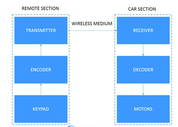
Blockdiagram
All reference designs on this site are sourced from major semiconductor manufacturers or collected online for learning and research. The copyright belongs to the semiconductor manufacturer or the original author. If you believe that the reference design of this site infringes upon your relevant rights and interests, please send us a rights notice. As a neutral platform service provider, we will take measures to delete the relevant content in accordance with relevant laws after receiving the relevant notice from the rights holder. Please send relevant notifications to email: bbs_service@eeworld.com.cn.
It is your responsibility to test the circuit yourself and determine its suitability for you. EEWorld will not be liable for direct, indirect, special, incidental, consequential or punitive damages arising from any cause or anything connected to any reference design used.
Supported by EEWorld Datasheet
EEWorld
subscription
account

EEWorld
service
account

Automotive
development
community

Robot
development
community

About Us Customer Service Contact Information Datasheet Sitemap LatestNews


Room 1530, 15th Floor, Building B,
No.18 Zhongguancun Street,
Haidian District,
Beijing, Postal Code: 100190
China
Telephone: 008610 8235 0740
 京公网安备 11010802033920号


 RNC50H4990FRRE6