The circuit shown in Figure 1 is a flexible current transmitter that converts the differential voltage output of a pressure sensor into a 4 mA to 20 mA current output.
Optimized for a variety of bridge voltage or current driven pressure sensors, this circuit uses only 5 active components and has a total unadjusted error of less than 1%. The power supply range is 7 V to 36 V, depending on the component and sensor driver configuration.
The inputs of this circuit are ESD protected and provide voltage protection above the supply rails, making it ideal for industrial applications.


This design provides a complete 4 mA to 20 mA transmitter pressure sensor measurement solution. There are three important circuit stages: sensor excitation driver, sensor output amplifier, and voltage-to-current converter.
The total current required by the circuit (excluding bridge drive current and output current) is 5.23 mA (maximum), as shown in Table 1.
| element |
Current(mA) |
| ADR02 |
0.80 |
| ADA4091-4 |
1.00 |
| AD8226 |
0.43 |
| R5, R6 at 6 V |
0.60 |
| R7, R8 at 5 V |
0.40 |
| R13 at 2 V |
2.00 |
| Total |
5.23 |
Excitation: Voltage Drive Configuration
Either voltage drive or current drive is required, depending on the pressure sensor selected. This circuit uses a quarter of an ADA4091-4 (U2A) and supports one of two options with different configurations selected via switch S1. Figure 2 shows the voltage drive configuration, with S1 positioned closest to the identification mark (see the complete circuit layout and schematic in the CN0295 Design Support package: http://www.analog.com/CN0295-DesignSupport . Voltage drive typically uses the gain of this stage (1 + R5/R6) configured for a 6 V bridge drive voltage. Other drive voltages can be obtained by appropriately changing the resistor ratio:

Note that the supply voltage V CC should be at least 0.2 V higher than the bridge drive voltage so that U2A has sufficient headroom. ADA4091-4:

![]()
The ADA4091-4 op amp was chosen for this circuit because of its low power consumption (250 μA per amplifier), low offset voltage (250 μV), and rail-to-rail input and output characteristics.
ADR02 was selected as the 5 V reference voltage source because of its accuracy (Grade A: 0.1%, Grade B: 0.06%) and low quiescent current (0.8 mA).


Excitation: Current Drive Configuration
By moving S1 farthest away from the identification mark, the circuit can be switched to the current-driven configuration shown in Figure 3.
In current drive mode, the circuit configuration is R4 = 2.5 kΩ and I DRIVE = 2 mA. Use the following equation to select the R4 value to obtain a lower or higher I DRIVE value.

The driving voltage V DRIVE can be calculated by the following formula :
![]()
The V CC supply requires 0.2 V headroom, so::

![]()


Bridge Output Instrumentation Amplifier and Offset Circuit
The bridge output is filtered with a common-mode filter with a bandwidth of 39.6 kHz (4.02 kΩ, 1 nF) and a differential-mode filter with a bandwidth of 1.98 kHz (8.04 kΩ, 10 nF).
The AD8226 is an ideal instrumentation amplifier choice because of its low gain error (0.1%, Class B), low offset (58 μV at G = 16, Class B; 112 μV at G = 16, Class A), and excellent gain nonlinearity. Linearity (75 ppm = 0.0075%) and rail-to-rail input and output characteristics.
The AD8226 instrumentation amplifier amplifies the 100 mV FS signal 16 times to 1.6V using a gain setting resistor of R3 = 3.28 kΩ. The relationship between gain G and R3 is as follows:
![]()
Where, G = 16, R3 = 3.2933 kΩ. Choosing the nearest standard 0.05% value for R3 (3.28 kΩ) gives a gain of G = 16.06, for a total gain error of +0.4%.
For a 0 V bridge output, the output loop current should be 4 mA. This value is obtained by simply applying a +0.4 V offset to the REF input of the AD8226 instrumentation amplifier, as shown in Figure 1. The +0.4 V comes from the ADR02 5 V reference, using divider resistors R7/R8 and buffering the voltage with U2B.
Use the AD8226 5 V reference to set the drive voltage or current for the bridge and to set the 4 mA zero-scale offset. It has an initial accuracy of 0.06% (Grade B) and has 10 μV pp voltage noise. In addition, it can operate with supply voltages up to 36 V and consumes less than 1 mA, making it ideal for low-power applications.
voltage current conversion
The AD8226's 0 V to 100 mV input produces an output swing of 0.4 V to 2.0 V at V OUT . The U2C buffer applies this voltage across R13, producing a corresponding 0.4 mA to 2.0 mA current I13. Transistor Q1 then mirrors the I13 current to R12 and the resulting voltage is applied to R15, resulting in a final loop current of 4 mA to 20 mA. Transistor Q1 should have a high gain of at least 300 to minimize linearity errors caused by base current.
Output transistor Q2 is a 40 VP channel MOSFET power transistor dissipating 0.75 W at 25°C. The circuit has worst-case power dissipation with 20 mA output current into a 0 Ω loop load resistor and a VCC supply of 36 V. Q2 power dissipation under these conditions is 0.68 W. However, by selecting V CC so that it is at least 3 V above the maximum loop load voltage, Q2 power dissipation can be significantly reduced. This ensures that there is sufficient margin for the voltage drop across sense resistor R15.
Voltage power requirements
For the circuit to operate properly, the supply voltage V CC must be greater than 7 V to provide sufficient headroom for the ADR02 reference.
The minimum V CC supply voltage also depends on the bridge drive circuit configuration. In the voltage drive mode with V DRIVE = 6 V, the supply voltage V CC must be greater than 6.2 V so that U2A can maintain sufficient margin (see Figure 2).
In current drive mode, the supply voltage V CC must be greater than 11.2 V so that U2A can maintain sufficient headroom (see Figure 3).
The V CC supply voltage limit is 36 V (maximum).
Error Analysis of Active Components
Table 2 and Table 3 respectively represent the A and B level maximum errors and rss errors of AD8226 and ADR02 caused by active components in the system. Note that the ADA4091-2 op amp is only available in one grade level.
| error element |
error |
difference |
Error(%FSR) |
| AD8226-A ADR02-A ADA4091-4 (U2B) ADA4091-4 (U2C) ADA4091-4 (U2D) AD8226-A |
Offset Offset Offset Offset Gain |
112 µV 0.10% 250 µV 250 µV 250 µV 0.15% |
0.11% 0.02% 0.02% 0.02% 0.02% 0.15% |
| RSS offset RSS gain RSS FS error |
0.12% 0.15% 0.27% |
||
| Maximum offset Maximum gain Maximum FS error |
0.19% 0.15% 0.34% |
| error element |
error |
difference |
Error(%FSR) |
| AD8226-B ADR02-B ADA4091-4 (U2B) ADA4091-4 (U2C) ADA4091-4 (U2D) AD8226-B |
Offset Offset Offset Offset Gain |
58 µV 0.06% 250 µV 250 µV 250 µV 0.10% |
0.06% 0.01% 0.02% 0.02% 0.02% 0.10% |
| RSS offset RSS gain RSS FS error |
0.07% 0.10% 0.17% |
||
| Maximum offset Maximum gain Maximum FS error |
0.13% 0.10% 0.23% |
Total circuit accuracy
A reasonable approximation of the total error due to resistor tolerance is to assume that each critical resistor contributes equally to the total error. The six critical resistors are R3, R7, R8, R12, R13, and R15. The worst-case tolerance due to the 0.1% resistor results in a maximum total resistance error of 0.6%. If the rss error is assumed, the total rss error is 0.1√6 = 0.245%.
Adding the 0.6% worst-case resistor tolerance error to the worst-case error due to active components (Class A) from the previous article, we get:
These errors assume the calculated value of the resistor, so the error comes only from its tolerance.
Although the circuit is allowed to have a total error of 1% or less, if better accuracy is required, the circuit needs to have offset and gain adjustment capabilities. For a 4 mA output and zero-scale input, the offset can be calibrated by adjusting R7 or R8, and then for a full-scale 100 mV input, full scale can be adjusted by changing R3. These two adjustments are independent of each other; offset calibration is assumed to occur first.
Actual error data for the circuit is shown in Figure 4, where V CC = 25 V. The total output current error (%FSR) is calculated by dividing the difference between the ideal and measured output current by the FSR (16 mA) and multiplying the result by 100.


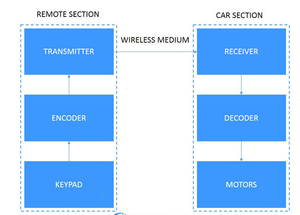
Blockdiagram
All reference designs on this site are sourced from major semiconductor manufacturers or collected online for learning and research. The copyright belongs to the semiconductor manufacturer or the original author. If you believe that the reference design of this site infringes upon your relevant rights and interests, please send us a rights notice. As a neutral platform service provider, we will take measures to delete the relevant content in accordance with relevant laws after receiving the relevant notice from the rights holder. Please send relevant notifications to email: bbs_service@eeworld.com.cn.
It is your responsibility to test the circuit yourself and determine its suitability for you. EEWorld will not be liable for direct, indirect, special, incidental, consequential or punitive damages arising from any cause or anything connected to any reference design used.
Supported by EEWorld Datasheet
EEWorld
subscription
account

EEWorld
service
account

Automotive
development
community

Robot
development
community

About Us Customer Service Contact Information Datasheet Sitemap LatestNews


Room 1530, 15th Floor, Building B,
No.18 Zhongguancun Street,
Haidian District,
Beijing, Postal Code: 100190
China
Telephone: 008610 8235 0740
 京公网安备 11010802033920号

 AM29F040-90PC