This project uses the following chips:
Heze Air001 microcontroller,
SL2.0 chip, and
LM358 op-amp.
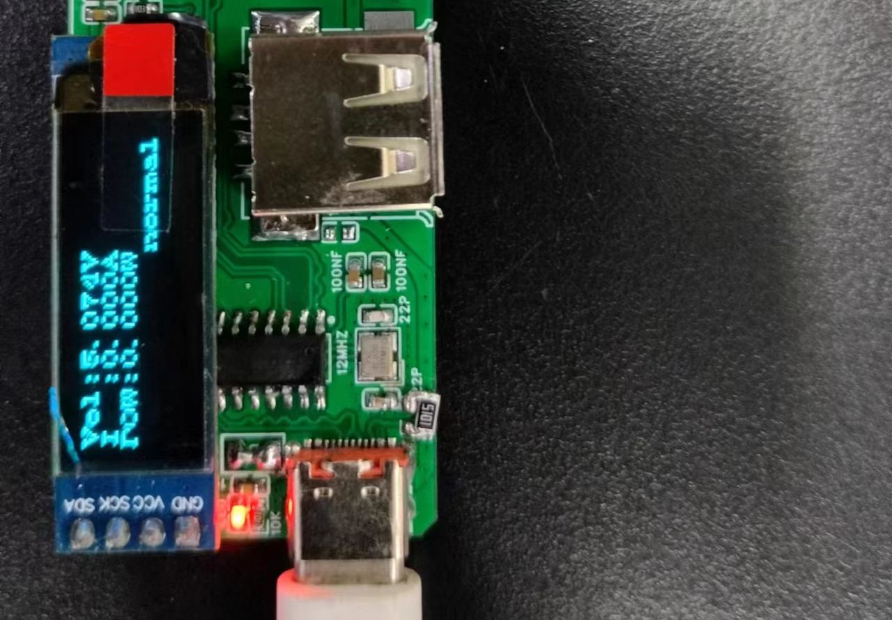
This docking station can display voltage, current, and power information, and can detect USB short circuits. The cost is currently only 9.9 yuan, with the main cost being the OLED screen. Further cost reduction could be achieved by replacing the OLED with an LCD or even LED, further reducing costs. The docking station currently works perfectly with a keyboard and mouse, and the USB flash drive read speed is 30MB/s, while the upload speed is 12MB/s. This basically meets daily needs. Note that this project requires some experience in microcontroller operation, experience using the Heze Air001 chip, and familiarity with AirISP (if you don't have one yet, buy one now, hehe, a 0.7 yuan chip is a steal!). The schematic may not match the PCB; avoid regenerating the PCB to prevent component loss. The program is not perfect; this docking station uses a 0.91-inch OLED (driver is 1306). Test images will be provided later. The detected voltage is quite close to the multimeter reading.
The following is a test of the current detection. A load cell was used to simulate the operation of the device.
Note: The 0-ohm resistor near the Type-C port is a fuse; you can choose one accordingly. The current range is 0~0.4A; the voltage range is 0~5.6V. The resistor used is a 1% precision ordinary resistor (this is the only one I have). If possible, purchase a higher precision resistor. The maximum voltage of this docking station should not exceed 5.5V, otherwise it may easily burn out the chips. Therefore, avoid using it in scenarios where PD/QC fast charging is used. The BOM (Bill of Materials) does not match.
Principle: The 5V voltage flows from the Type-C port, first through the fuse, then through the USB port, to the current sensing resistor, and finally back to GND. The current-sensing resistor is only 0.01 ohms. Current flowing through it generates a weak voltage that increases linearly with the current. Therefore, we can use the microcontroller's ADC to sample the voltage across the current-sensing resistor to determine the USB current. However, because the resistance is so small, the generated voltage signal is too weak. Simply using the microcontroller's ADC will result in poor accuracy and a limited range. Therefore, using an LM358 as a proportional operational amplifier to amplify the voltage before sampling through the microcontroller's ADC improves the accuracy of current sampling. Using a Kelvin connection for the current-sensing resistor PCB will further enhance accuracy. Since the USB voltage is 5V, voltage sampling can be done directly using a resistor divider.
The following is the programming method. Thank you very much to Xv_9 for providing the program download tutorial!
The project is in the attachment. Programming
requires a TTL serial port, using a jumper wire. Connect the BOOT to 3.3V to enter download mode, and then run in floating mode.


 京公网安备 11010802033920号

 507-164J10009B


