MOONPILOT Flight Controller:
A Simulation
Introduction
The MOONPILOT flight controller is an STM32H743-based flight control hardware that supports mainstream flight control systems (BF/INAV/ARDUPILOT). Its features include:
1. Using the STM32H743VIH6 microcontroller with a main frequency up to 480MHz, it is more compatible with flight control systems that have deployed RTOS, in addition to BETAFLIGHT, and can also be used to deploy and verify your own navigation/control algorithms.
2. Nine SH1.0 connectors on the front panel meet the basic requirements for taking off a racing drone, allowing users to launch the aircraft without requiring specific soldering skills; an additional SWD port is designed to meet debugging needs.
3. Dual LDO design, with separate power supplies for the MCU and SENSORS, providing cleaner power input to each sensor.
4. The main/auxiliary inertial measurement units are optional, allowing users to select chips according to their needs (IMU0: ICM42688/ICM42605/MPU6000, IMU1: ICM42688/ICM42605).
5. Equipped with a USB anti-backlash circuit, TVS diodes, and a resettable fuse to enhance flight controller safety.
6. Except for the PWM resistor which uses eight 0201 resistors, all other resistors are packaged in 0402 or larger packages, reducing the difficulty of replication and repair.
External Interfaces
: 1. SWD debugging interface;
2. UART1-4, UART6-8, 7 serial ports in total;
3. PWM/DSHOT 1-4, 5-8, 9-10, of which 1-8 have connectors;
4. CAN bus, SPI bus (with 2 CS pins), I2C bus;
5. LED 1, BEEPER 1;
6. PIN_IO 2;
7. ADC voltage measurement 2, current measurement 2, RSSI 1, AIRSPEED * 1;
8. BEC 5V 2A, 10V (actual output 10.4V) 2A.
Internal interface
MCU
PWM
MCU
SERIAL
MCU
USB/ADC/I2C/LED
MCU
SPI(1/2/4)
MCU
SPI3/CAN
MCU
SWD/PINI
PB0
S1
PE8
Tx7
PA11
D-
PA5
SPI1_SCLK(IMU0)
PB3
SPI3_SCLK
PA14
SWCLK
PB1
S2
PE7
Rx7
PA12
D+
PA6
SPI1_MISO(IMU0)
PB4
SPI3_MISO
PA13
SWDIO
PA0
S3
PA9
Tx1
PC1
CURR1(0-3v3)
PD7
SPI1_MOSI(IMU0)
PB5
SPI3_MOSI
PD10
PINIO1
PA1
S4
PA10
Rx1
PA7
CURR2(0-3v3)
PA13
GYRO1_CS(IMU0)
PD4
SPI3_CS1
PD11
PINIO2
PA2
S5
PD5
Tx2
PC0
VBAT1(1:11)
PB2
GYRO1_EXTI(IMU0)
PE2
SPI3_CS2
-
-
PA3
S6
PD6
Rx2
PA4
VBAT2(1:21)
PB13
SPI2_SCLK(AT7456E)
PC12
SDIO_CLK
-
-
PD12
S7
PD8
Tx3
PC5
RSSI(0-3v3)
PB14
SPI2_MISO(AT7456E)
PD2
SDIO_CMD
-
-
PD13
S8
PD9
Rx3
PC4
AirSpeed(1:2)
PB15
SPI2_MOSI(AT7456E)
PC8
SDIO_D0
-
-
PD14
S9
PE1
Tx8
PB6
I2C1_SCL
PB12
AT7456E_CS(AT7456E)
PC9
SDIO_D1
-
-
PD15
S10
PE0
Rx8
PB7
I2C1_SDA
PE12
SPI4_SCLK(IMU1)
PC10
SDIO_D2
-
-
PE5
S11
PB9
Tx4
PB10
I2C2_SCL(DPS310)
PE13
SPI4_MISO(IMU1)
PC11
SDIO_D3
-
-
PE6
S12
PB8
Rx4
PB11
I2C2_SDA(DPS310)
PE14
SPI4_MOSI(IMU1)
PD1
CAN_Tx
-
-
PA8
LED_STRIP
PC6
Tx6
PE3
LED0
PE15
GYRO2_EXIT(IMU1)
PD0
CAN_Rx
-
-
PA15
BEEPER
PC7
Rx6
PE4
LED1
PE11
GYRO2_CS(IMU1)
PD3
CAN_SILENT
-
-
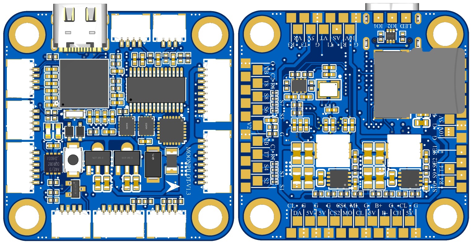
Connector Wiring
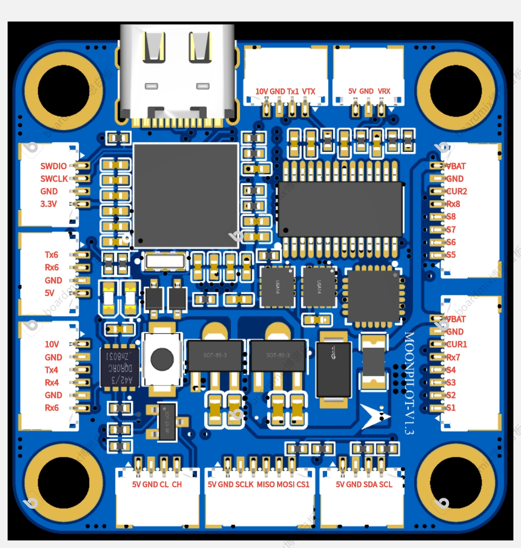
Diagram
Test Progress
2024.08.05---Static testing of connectors: ESC, image transmission, OSD, camera, remote control receiver, and ESC output all functioned normally. 2024.09.02
---Static testing of BEEPER and LED strip showed normal output. 2024.09.20
---Static testing of the SD card black box function showed normal operation. In full-speed recording mode, attitude calculation, attitude control, and OSD outputs were all normal and without any lag. 2024.11.10
---Dynamic flight test: ALong X1 frame, 800mW Panda image transmission, ELRS 2.4G receiver. Black box recording was enabled, variable PWM was used, and all possible configurations were fully utilized. OSD attitude display was smooth and fluid.
Test Flight Video:
MoonPilot H743 Test Flight Record 2024.11.10 (Bilibili video link)
Creation Rationale:
The author has long been engaged in flight control and navigation algorithm-related work, and has used PIXHAWK-2.4.8 (a domestically produced knock-off), Anonymous Flight Controller, and PIXHAWK-4. After analyzing the BETAFLIGHT open-source code, and referring to the pin design of the MATEK-H743 flight controller (this hardware can be directly flashed with MATEKH743 firmware), the preliminary design of MoonPilot was completed.
This flight controller is designed with a straightforward hardware approach, providing significant computational redundancy (EKF, UKF, ADRC, etc.) for students' algorithm design. The on-chip 2MB FLASH is more than sufficient even for deploying an RTOS. An SWD interface is also included to facilitate debugging of the flight controller's software and hardware.
When designing the IMU circuit, considering the current transition from the discontinued MPU6000 to the ICM42688P, and given that the MPU6000's performance remains strong, redundant pads were incorporated into the IMU0 design.
If you have any questions about the design of this flight controller, please feel free to discuss them in the comments section. Hardware experts are also welcome to review the design of this flight controller.


 京公网安备 11010802033920号

 R1172H241A


