PDF_Hikvision Thermal Imaging Module TB-4117-3-S Adapter Parameter Adjustment Backplane.zip
Altium Hikvision Thermal Imaging Module TB-4117-3_S Adapter Parameter Adjustment Backplane.zip
PADS_Hikvision Thermal Imaging Module TB-4117-3_S Adapter Parameter Adjustment Backplane.zip
BOM_Hikvision Thermal Imaging Module TB-4117-3_S Adapter Parameter Adjustment Backplane.xlsx
Bilibili video: https://www.bilibili.com/video/BV1h14y1B7TA/
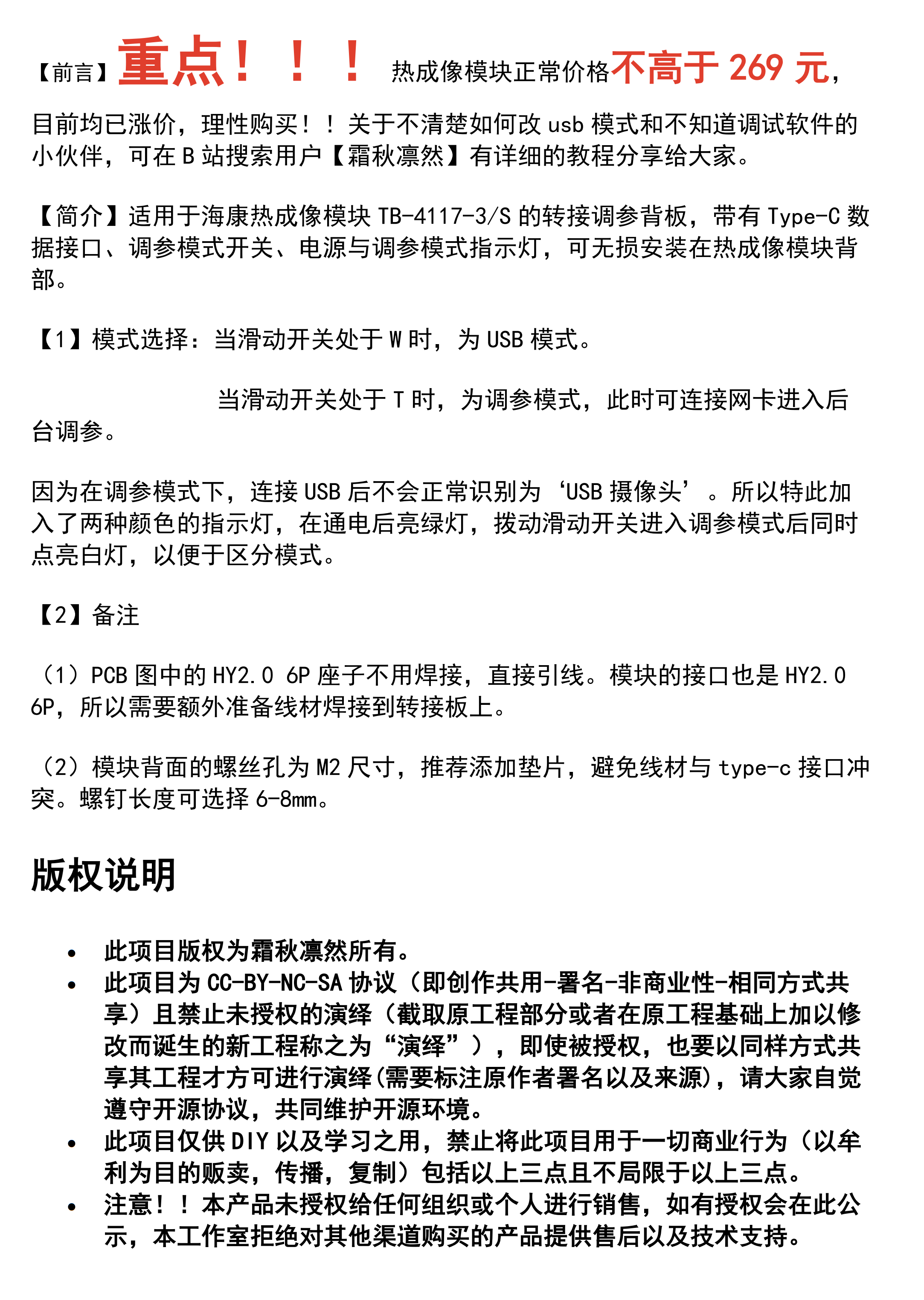
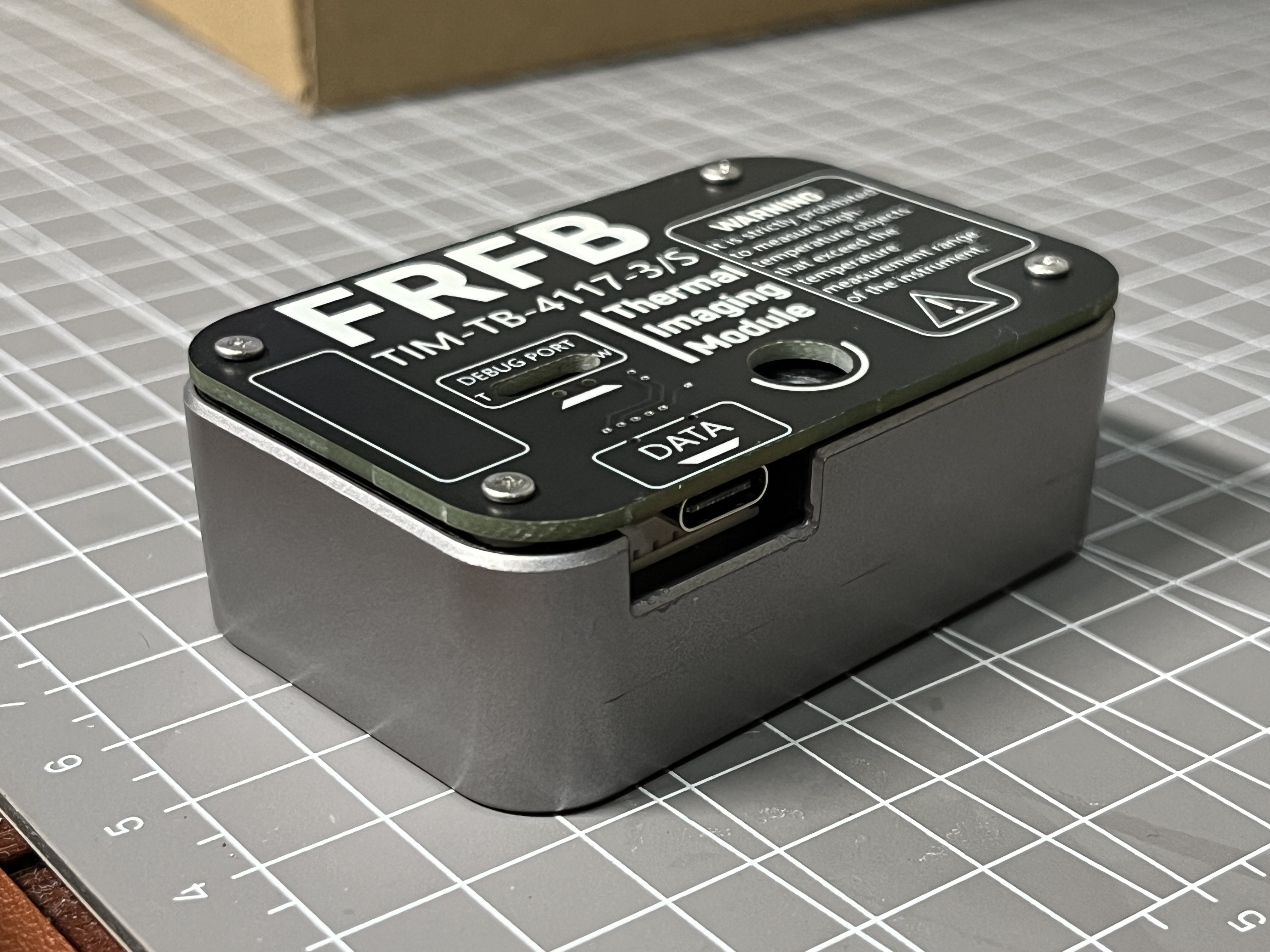
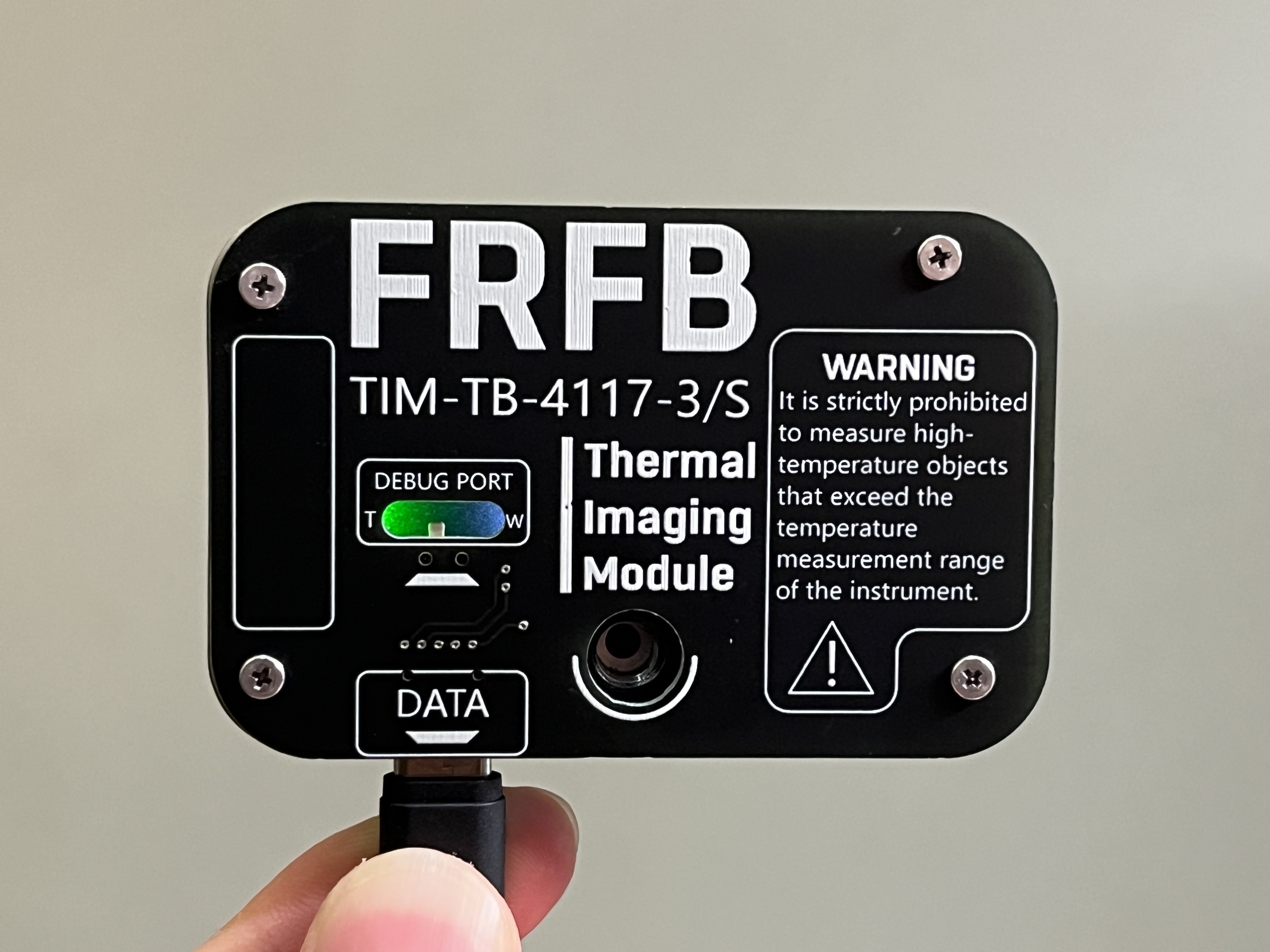
I. Project Description
1. An electric mosquito repellent liquid heater based on STC8G1K08 as the main controller, using a carbon film resistor as the heating element.
2. Supports Type-C 5V input and C to C cable.
3. Lower cost compared to the PTC heating element used in traditional electric mosquito repellents.
4. Can be powered by a power bank, offering portability and convenience for outdoor use.
5. Overall low hardware cost, simple circuit design, and easy to replicate.
II. Hardware Principle
Traditional electric mosquito repellent working principle:
Traditional electric mosquito repellents on the market operate through a self-locking switch, using a PTC heating element for constant temperature heating. Heating the wood fiber core of the mosquito repellent liquid causes the liquid in the bottle to evaporate into the air.
Hardware principle of this project:
1. Utilizing the Joule heating effect, when current flows through a series resistor, the current does work, consuming electrical energy and generating heat.
2. 3. A PWM-driven P-channel MOSFET AO3401 is used to control heating and stop heating.
4. A constant temperature is controlled using an NTC thermistor, reducing heating power when the preset temperature (105℃) is reached.
5. A push-button switch and an LED are used as status indicators.
III. Temperature Measurement Principle:
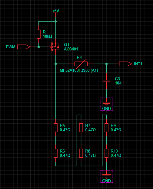
The driving and temperature measurement circuit are shown in the diagram above. The left side of the NTC resistor can be considered a push-pull output of 0V or 5V.
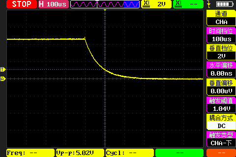
Because the pull-down resistor (load resistor) is sufficiently small, a RC charging/discharging delay waveform is generated on the INT1 pin at the instant of conduction or deactivation.
Combined with the trigger level of the IO pin, the resistance
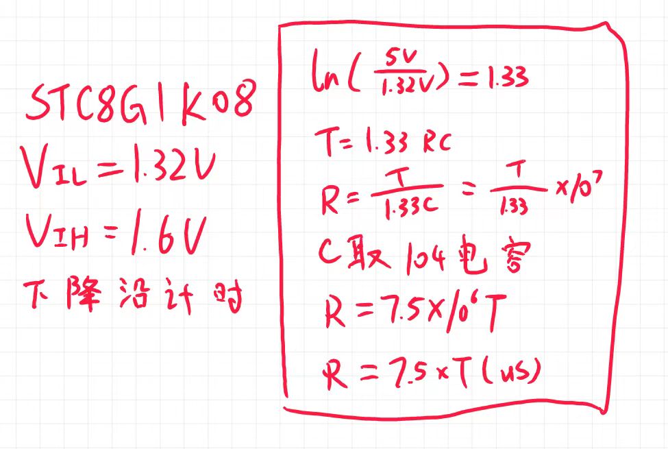
principle of the NTC is somewhat similar to that of an integrating ADC. For specific implementation details, please refer to the source code. The process is as follows:
when the output is off, T1 timing and INT1 external interrupt are enabled; when the external interrupt is triggered, T1 timing is stopped. At this point, the time difference from power supply to trigger can be obtained.
This time difference can then be used to look up the current temperature in a table. Therefore, the microcontroller does not need a formula to calculate the resistance value. It's a clear trade-off between space and time.
Moreover, this microcontroller doesn't have an ADC peripheral, saving another two cents.
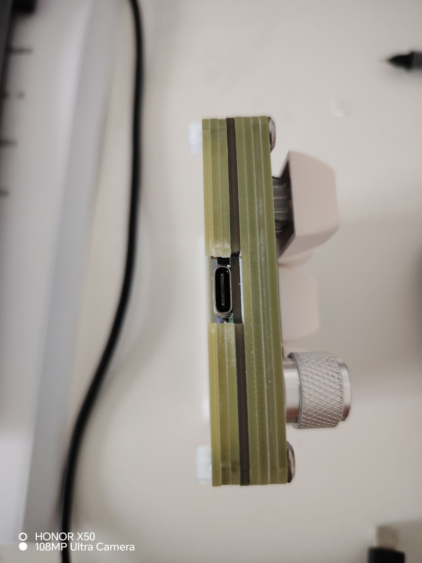
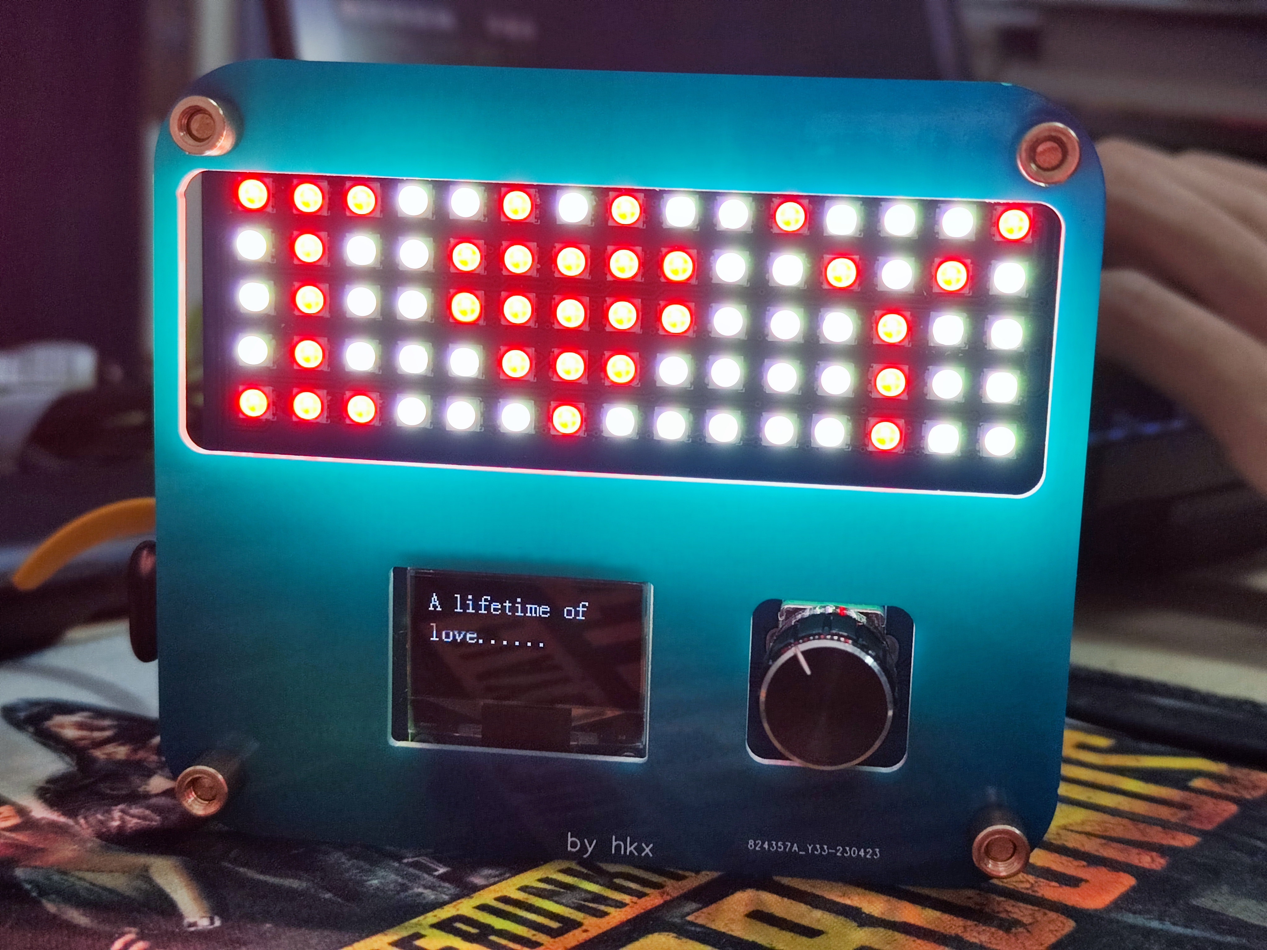
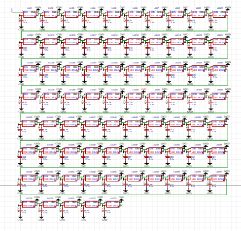
The design was inspired by finding a box of APM32F103 chips. I then looked around the plaza for small gadgets I could make and found a 9+1+1 knob keypad that looked really nice. However, the 32U4 chip it used was a bit expensive, so I designed one using APM32 to mimic the layout.
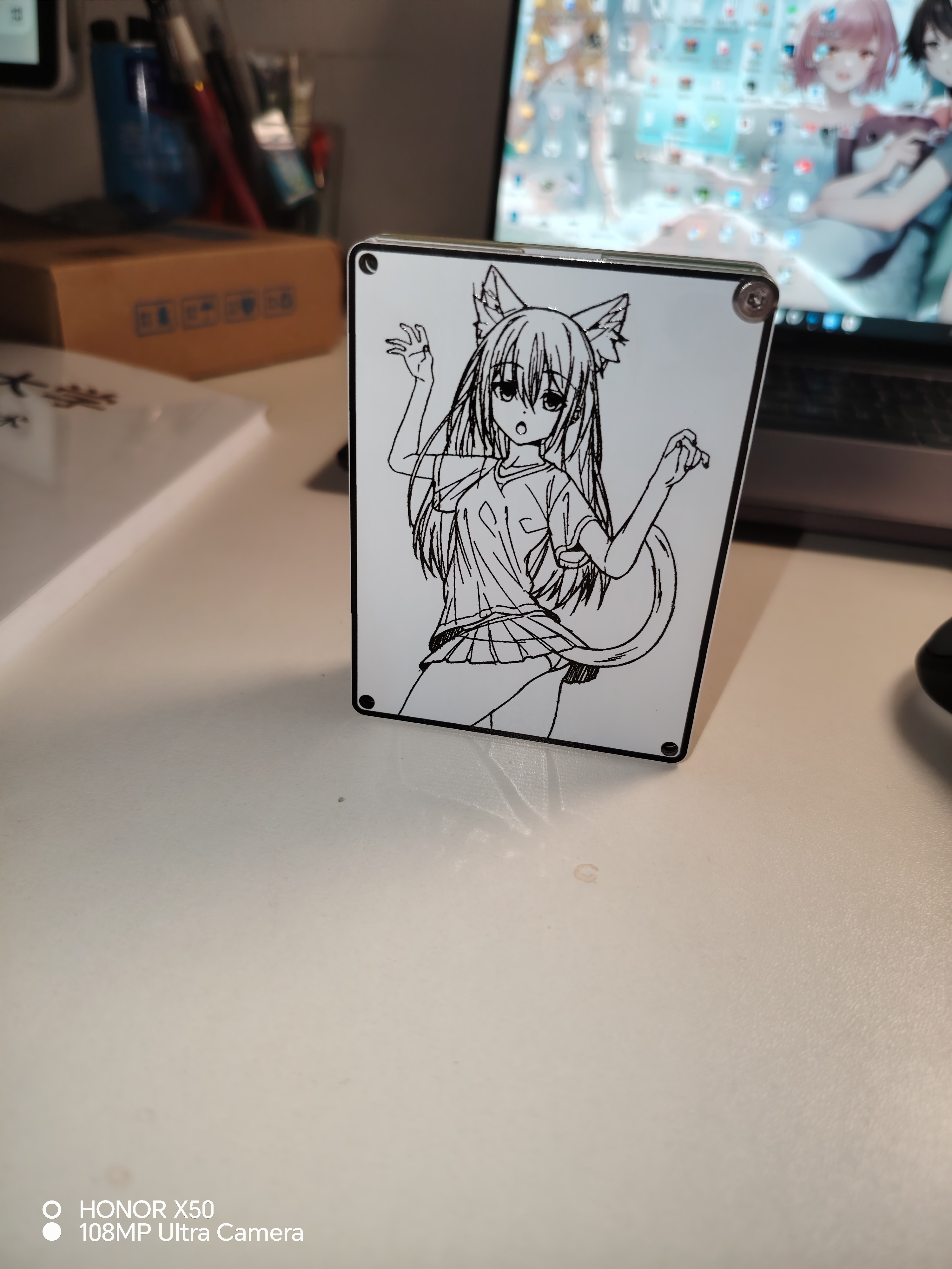
The numeric keypad uses a stacked PCB design, with M3 screws measuring 16mm in length. The keyboard supports Vial key remapping (currently, the encoder cannot remap keys, but this can be achieved by modifying the code). Source code and firmware are attached; see the
front,
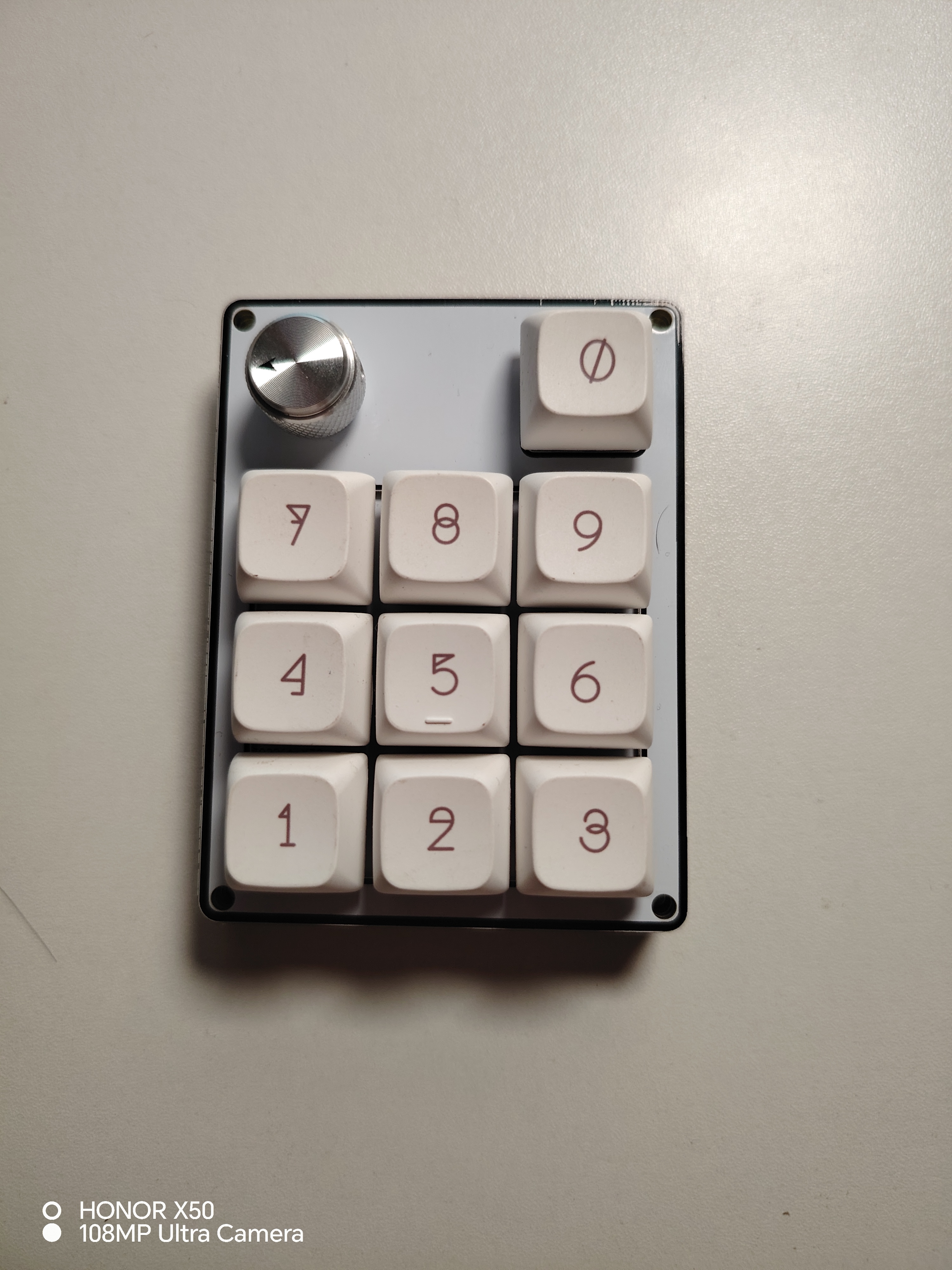
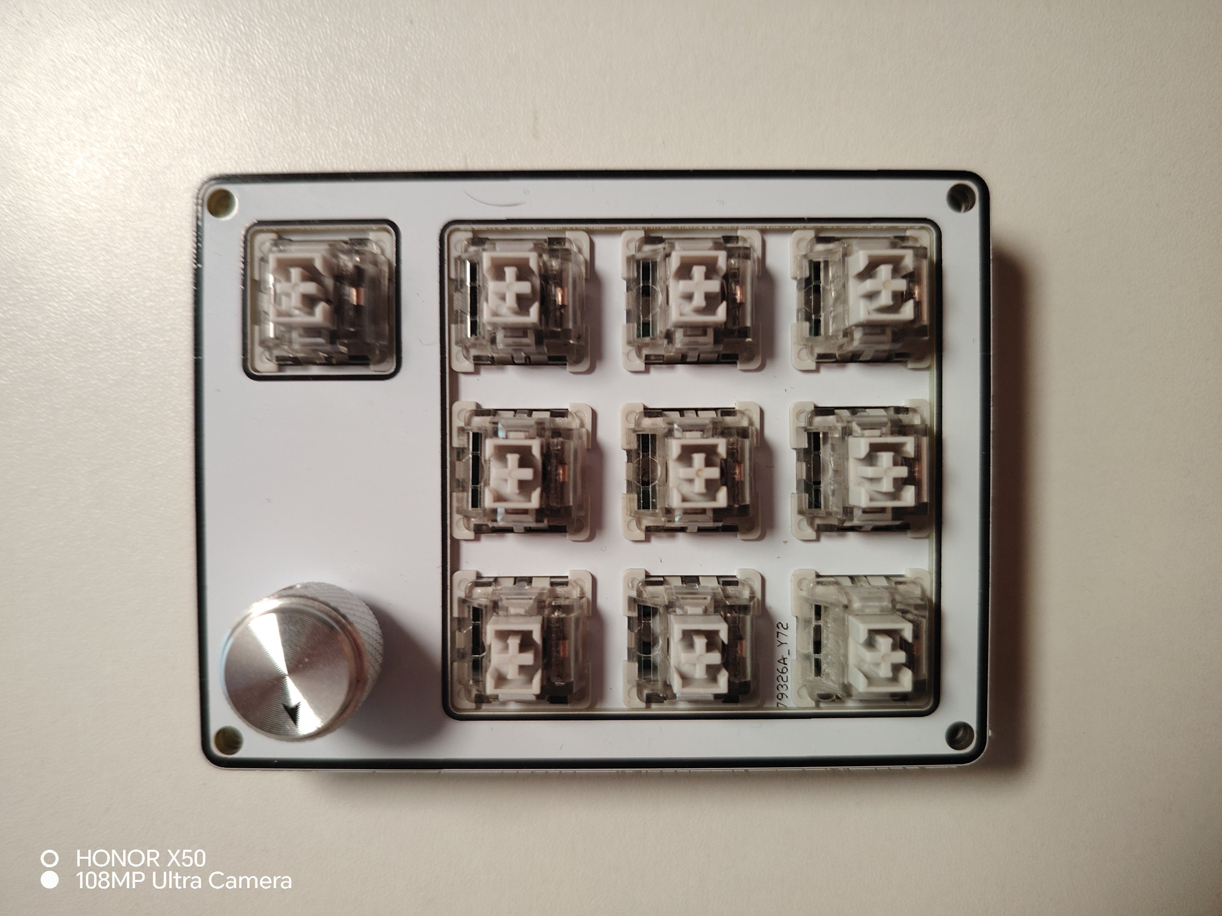
side,
stacked PCB, and layered back
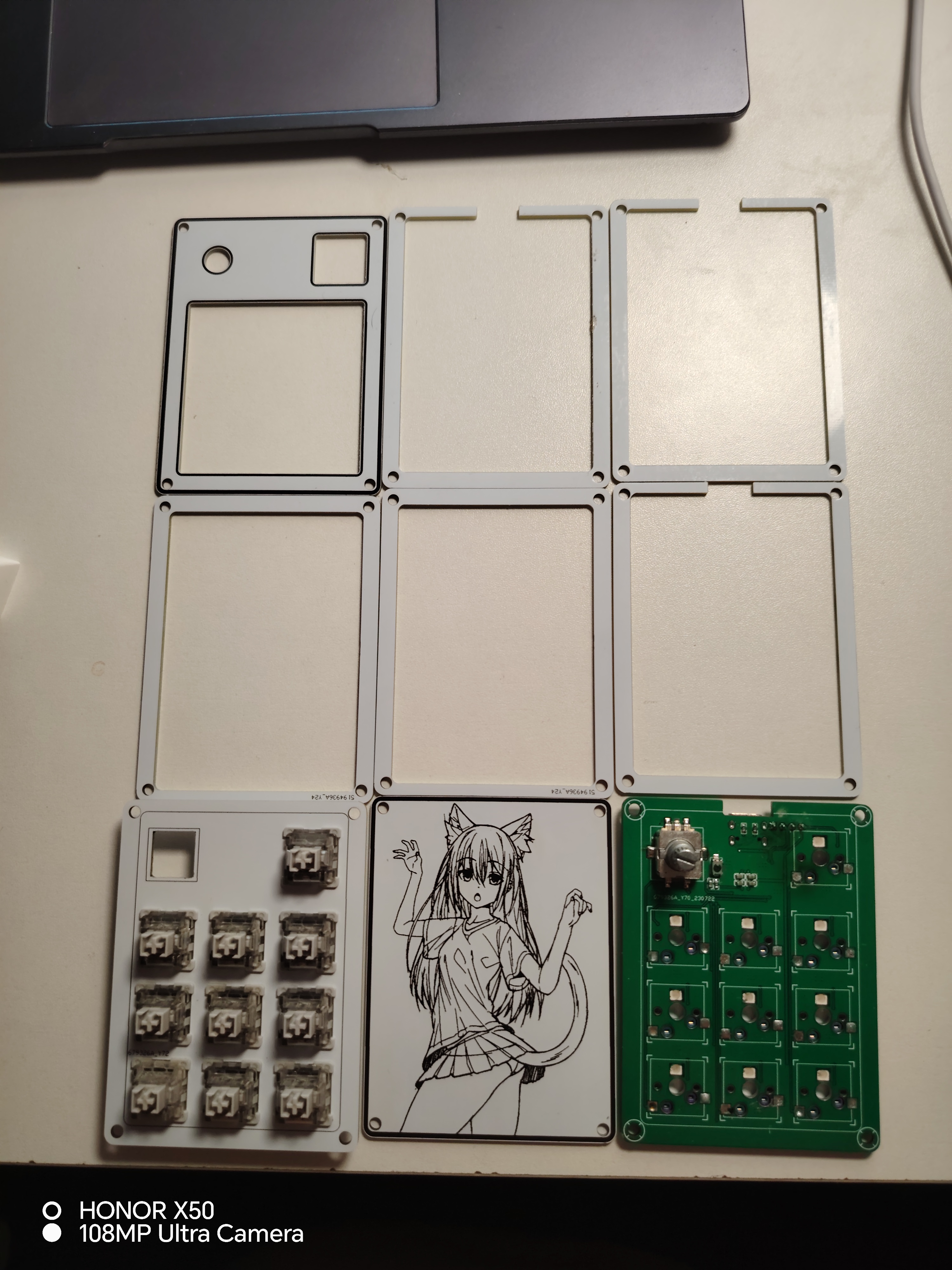
panel.
9+1+1.rar
binepad_bn006_vial.bin
PDF_9+1+1 rotary keypad apm3.zip
Altium_9+1+1 rotary keypad apm3.zip
PADS_9+1+1 rotary keypad apm3.zip
BOM_9+1+1 rotary keypad apm3.xlsx
91488
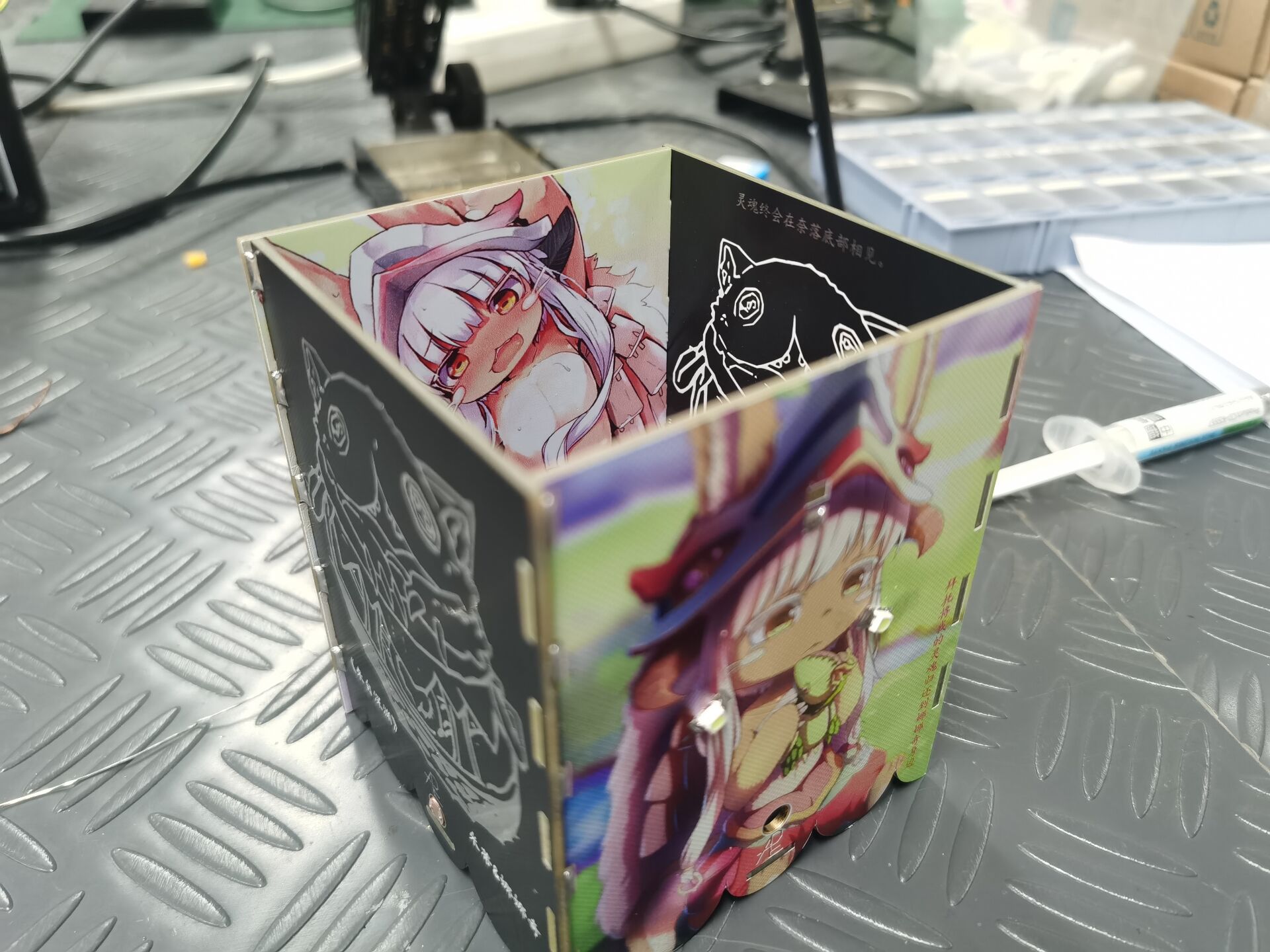
[Color Silkscreen Printing] Photosensitive Pen Holder "From the Abyss"
A pen holder with a built-in light, controlled by a very simple light-sensitive circuit. It doesn't light up in strong light, but illuminates in weak light. A DIY project inspired by the anime "Made in Abyss." Nanachi is so cute!
The photosensitive box
is a very simple and interesting circuit, suitable for beginners.
The photosensitive circuit turns off the LED when the ambient light is strong and turns on when the ambient light is weak. The photoresistor R2 has low resistance in strong light and high resistance in weak light, thus creating a voltage divider on the base of the transistor, thereby controlling the transistor's on/off state. R1 is best tested at 24kHz brightness; you can replace it with a more suitable resistor for voltage division.

The circuit feasibility has been tested and the effect is good.
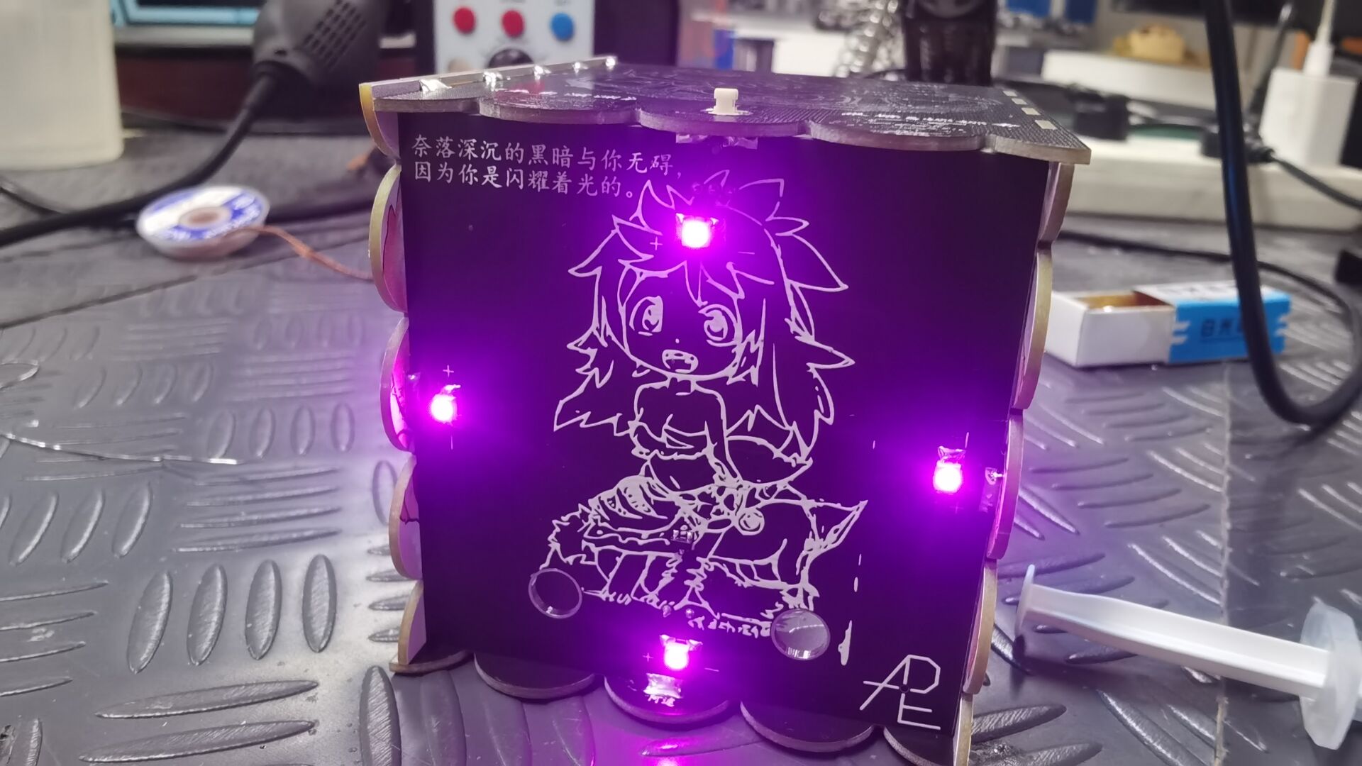
The entire circuit is on the bottom PCB (the silkscreen is Mitty from the Abyss).

The bottom circuit connects adjacent PCBs through windowed soldering
, which not only connects the circuit but also strengthens the stability of the box.
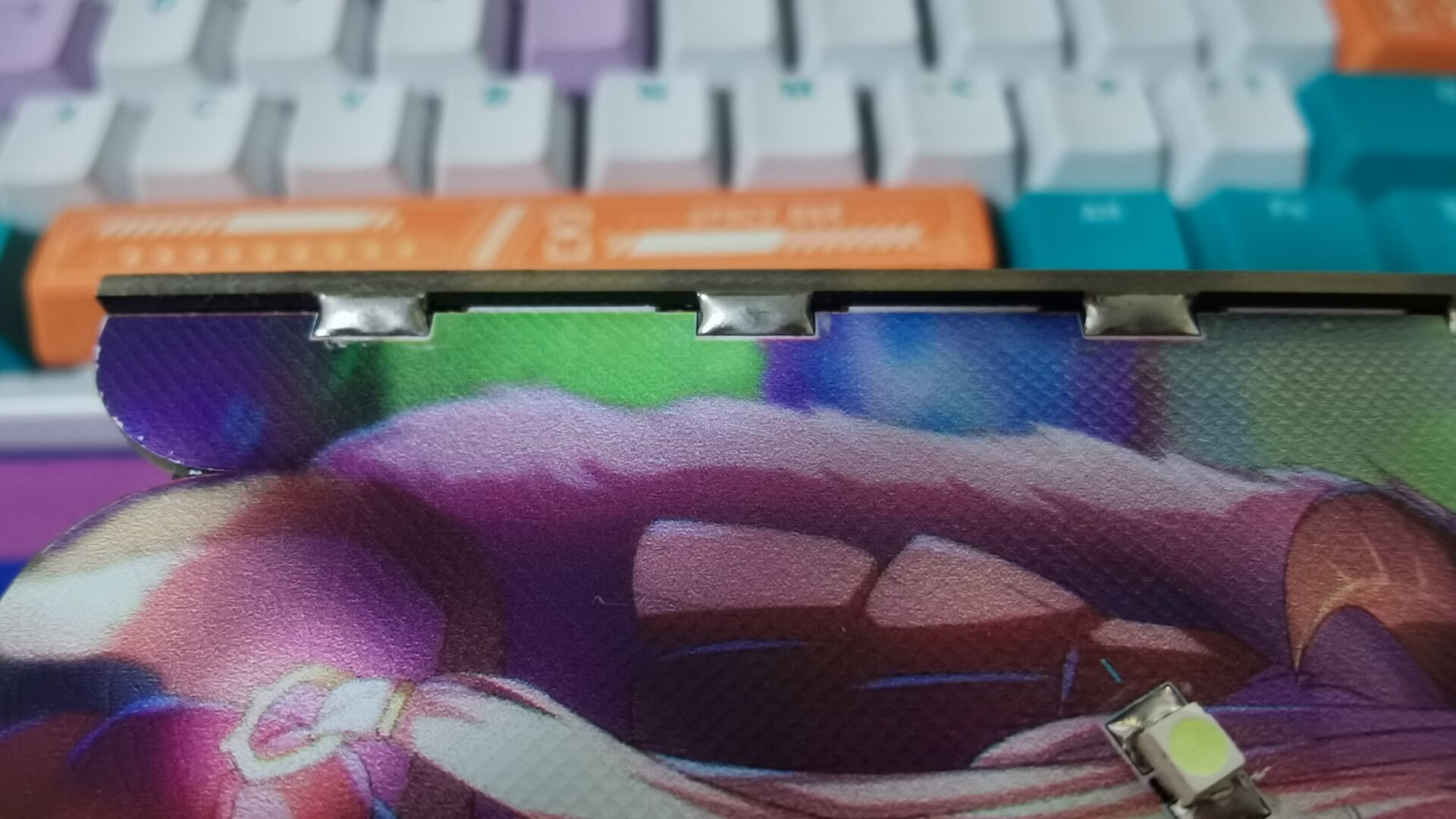
Windowed connections are made at the board edges, and the five boards are connected together with solder,
making it more robust and aesthetically pleasing. At the same time, the circuit is guided to the four side boards, realizing multi-board connection and allowing the sides to light up as well. Front
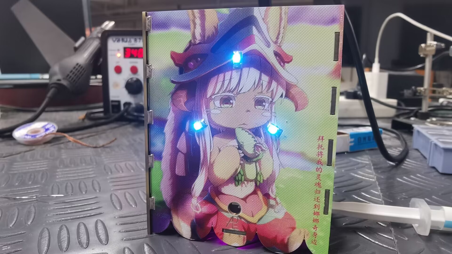
view (this picture is of Nanachi from the anime 'Made in Abyss').

Inside the box (still Nanachi) (ღ♡‿♡ღ).
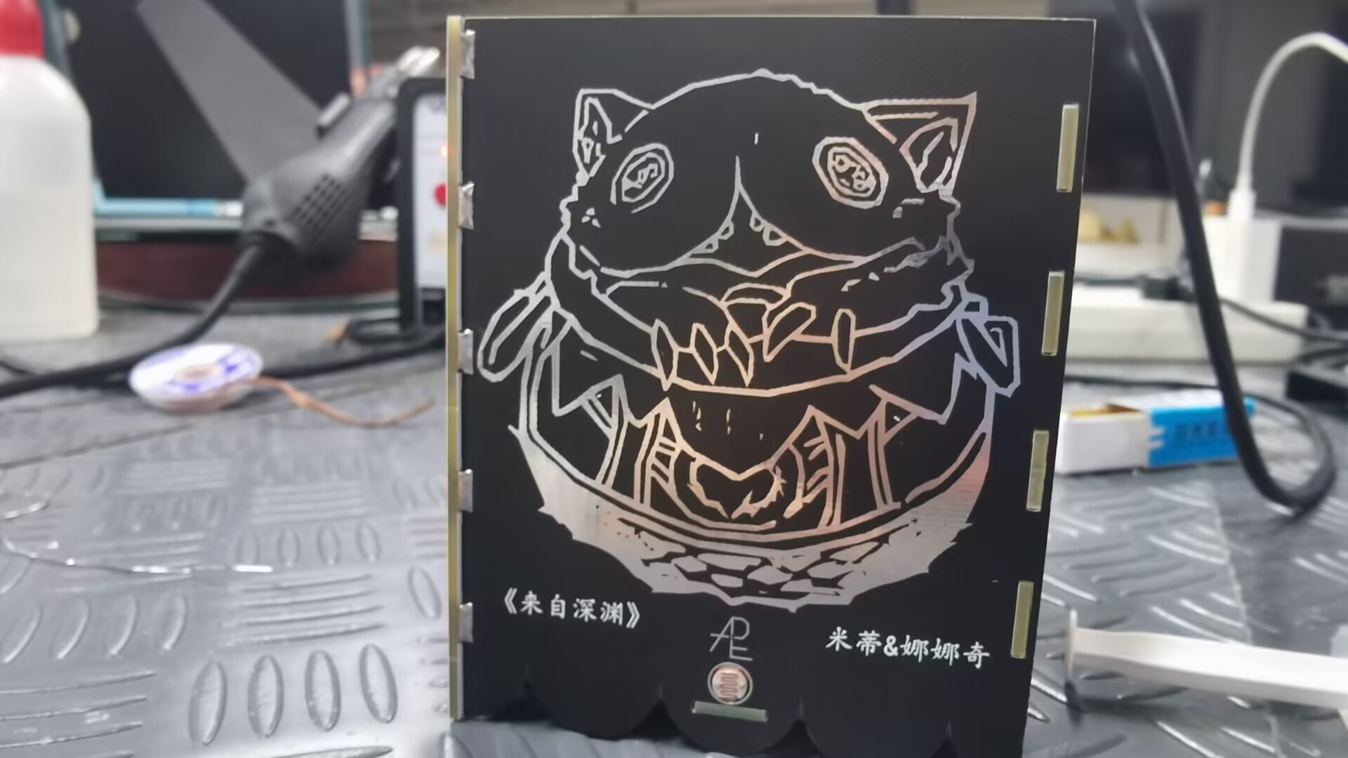
Side view (the silkscreen is of Mitty's jar from the Abyss).
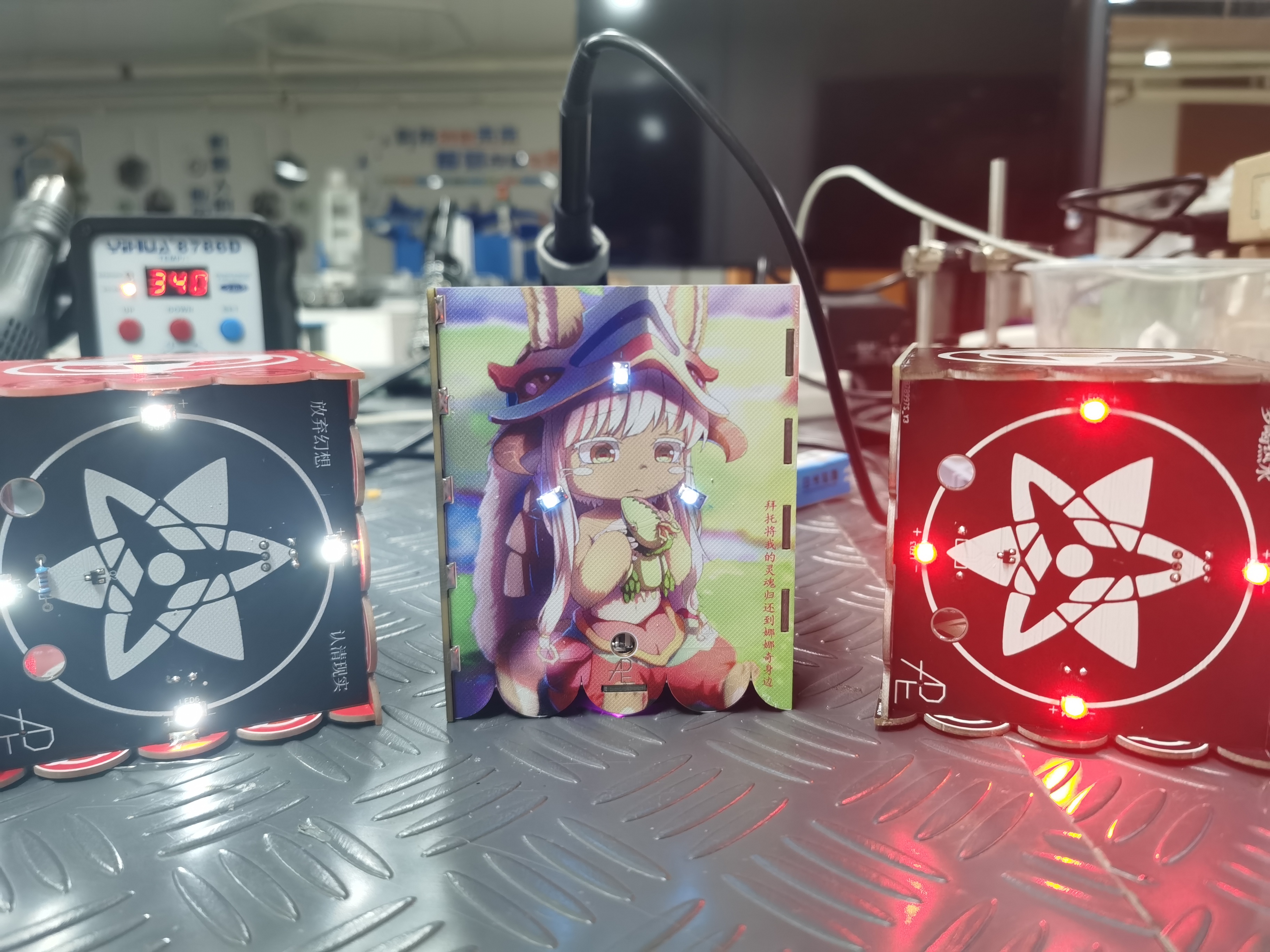

I filled it with stuff

and had my junior take a picture and
video on Bilibili. [Brothers, the JLCPCB color silkscreen is as pretty as my junior! O(≧▽≦)O] I assembled a photosensitive pen holder from 5 PCBs! - Bilibili】
Bilibili link (You can see my junior here (。>∀): https://b23.tv/xlcmSK3
PDF_【Color Silkscreen】Photosensitive Pen Holder "From the Abyss".zip
Altium_【Color Silkscreen】Photosensitive Pen Holder "From the Abyss".zip
PADS_【Color Silkscreen】Photosensitive Pen Holder "From the Abyss".zip
BOM_【Color Silkscreen Printing】Photosensitive Pen Holder "From the Abyss".xlsx
91489
Candy Box Game Machine
A game console housed in a candy box (suitable for beginners)
The Candy Box Game Console


Project:
A while ago, I saw an open-source project from abroad that housed a pre-made Attiny85 game console inside a candy box. I found it interesting and thought it seemed simple to make, so I wanted to try replicating it. However, having never worked with Arduino before, I never imagined how difficult the process would be.
HEX file.zip
game code.zip
progisp.exe
Progisp User Manual.pdf
PDF_Candy Box Game Machine.zip
Altium_Candybox Game Console.zip
PADS_Candy Box Game Console.zip
BOM_Candy Box Game Machine.xlsx
91492
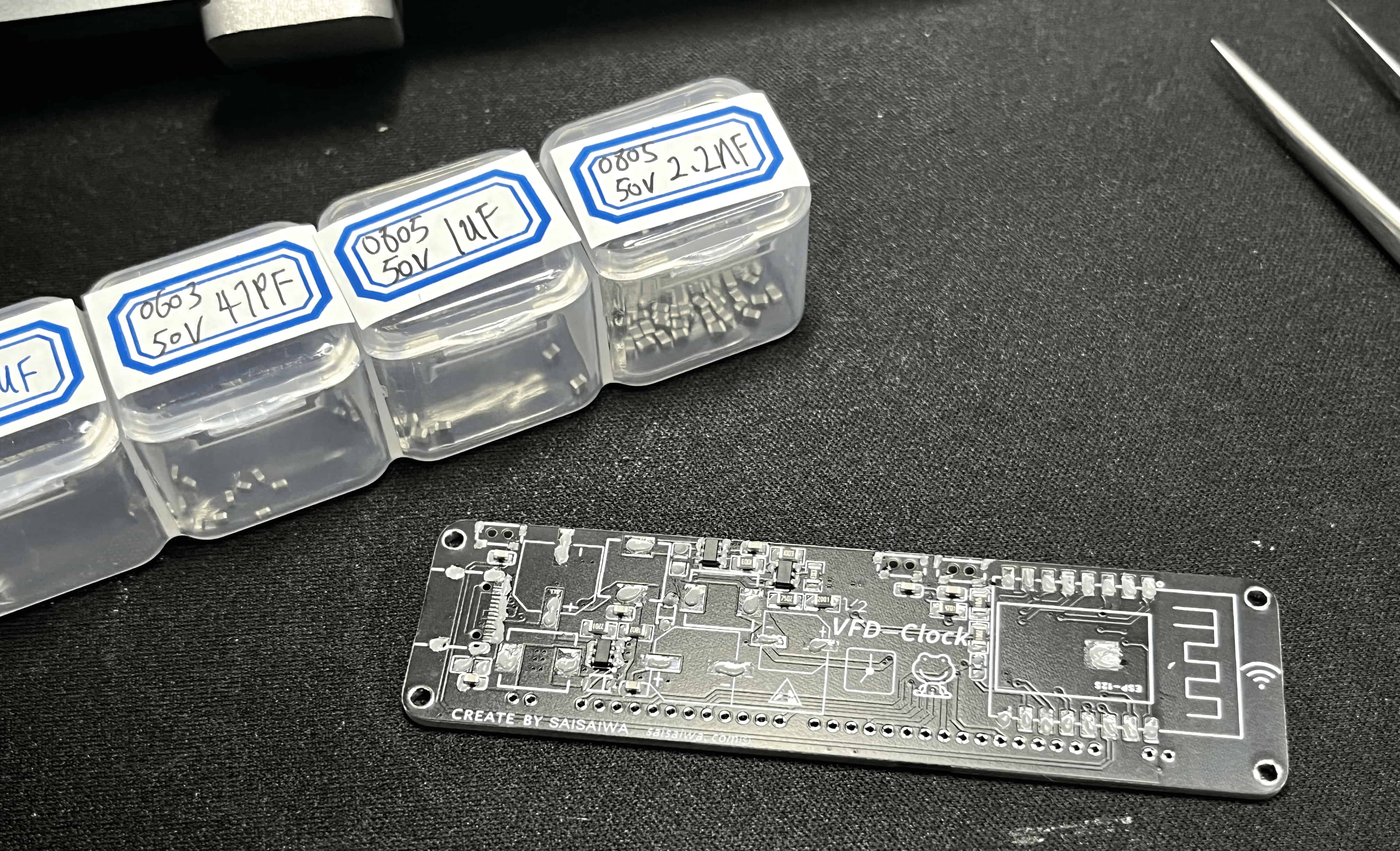
VFD 7-BT-317NK WIFI Clock
For the second version of the VFD Desktop Clock (7-BT-317NK)
, please visit: https://oshwhub.com/yc_chen/v2-vfd-7-bt-317nk-wifi-shi-zhong
This VFD driver circuit
design will adopt a low-cost solution. Previous VFD driver designs used a more expensive but transformerless solution.
This time, the negative voltage circuit will not use a high-cost IC chip that can invert and boost the voltage.
Instead, an MT3608 (0.30 each) with a Cuk circuit will be used to achieve the negative voltage, but two 10uH inductors (0.31 each) will be needed.
The filament driver will use a low-cost motor driver TC118S (0.13 each) in conjunction with PWM.
The VFD driver chip will still be the professional driver chip PT6315 (2.59 each), which is also the IC used in the datasheet.
Note
that this is the first version
, which is cheaper but has some drawbacks.
It is picky about power supplies; some power supplies may cause instability, and it does not support PD power supply.
Updated 2023-08-11
: The PT6315 was changed from a direct 5V Type-C power supply to an LDO 3.3V power supply, resolving the bug where some power supplies could not operate stably. (Schematic has been updated)
(For those who have already boarded up, please disconnect the 5V power supply jumper to the LDO 3.3 output pin) The second version
of the V2 board
has optimized stability and fixed known bugs . Please
refer to the second version link: https://oshwhub.com/yc_chen/v2-vfd-7-bt-317nk-wifi-shi-zhong
MCU Selection
For convenience and cost control, the ESP8266EX main controller is used -> ESP-12S (Anxinke - 3.5 yuan per module).
The automatic download circuit is designed with CH340C (1.49 yuan per module). Soldering is optional; you can also use a programmer by adding jumper wires to the pads.
A space is reserved for the design of an AHT21 temperature and humidity sensor, which can be soldered or omitted, but I will design the complete circuit.
Then there are three user buttons, plus a pink LED 0603 specification LED bead as an indicator.
The RSTB and IO0 pins are brought out to separate pads; no rest button is designed.
BOM Procurement
Notes: Resistors and capacitors in the schematic may have specifications like 0805 and 0603, which are not uniform. If you have resistors of different specifications (e.g., 0805 10K while my schematic uses 0603 10K), you can change the package size in the schematic or purchase 0603 resistors.
In this project, the main cost components are ESP-12S, PT6315, and CH340C. You can omit the automatic download circuit and program via flying wire soldering.
Soldering Verification Notes:
Please read this carefully. If you encounter soldering problems, please resolve them yourself.
Soldering Steps:
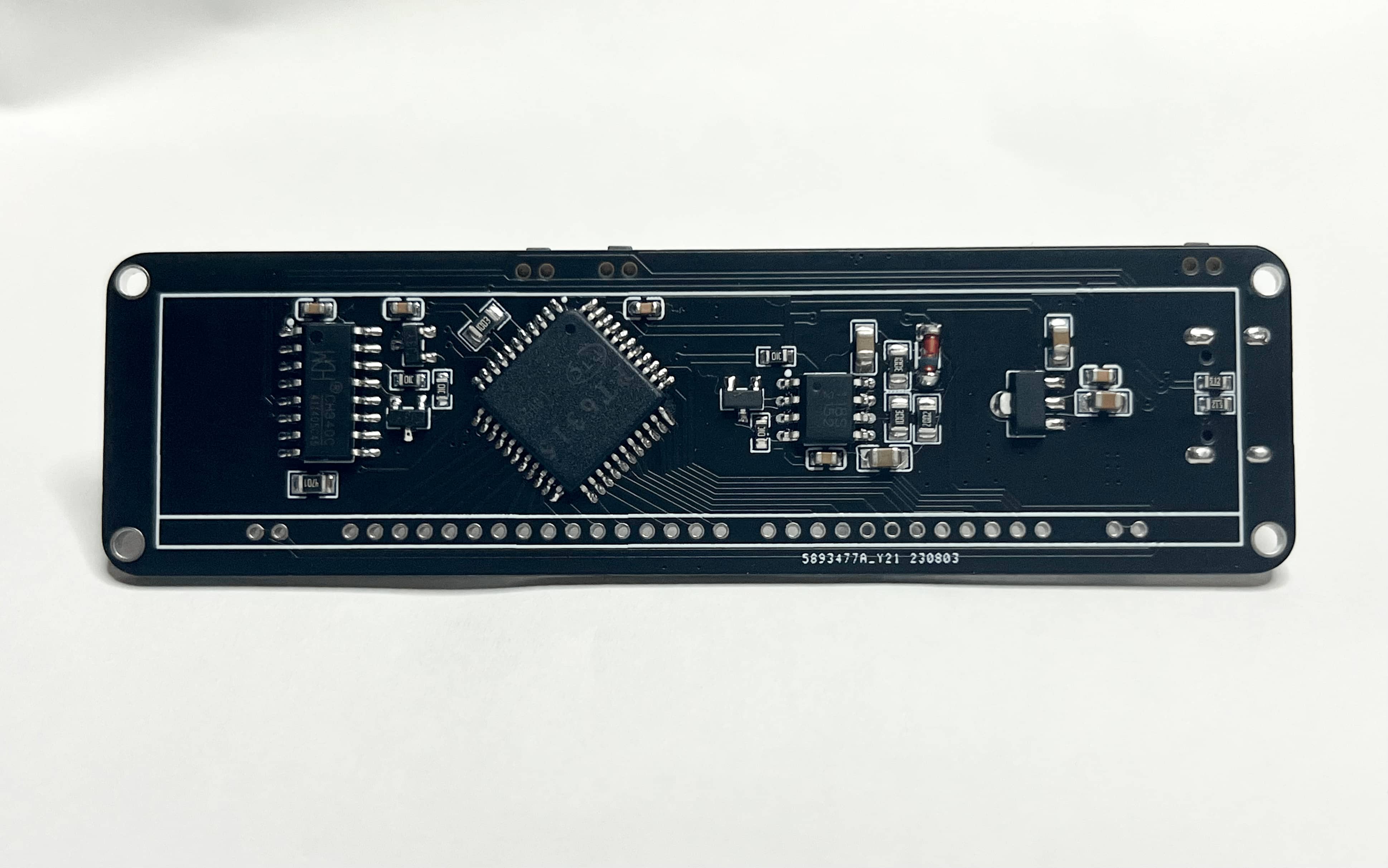
Solder the MCU portion on the back first. A heated soldering station is recommended.
Do not solder the front side first. After soldering the PT6315
, verify if there is a short circuit
and check the voltage: negative voltage output, +3.3V output. When soldering the PT6315,
it is recommended to use a soldering iron. Apply solder
paste to the pads, place the chip, and solder one pin around the perimeter for fixation. Then, drag the solder back and forth.
Don't be stingy with solder paste; if solder bridging
occurs, apply more paste. Prepare a handheld magnifying glass to check for solder bridging; check several times.
You should have already completed the soldering steps above. Don't rush to solder the VFD screen. Next, see my instructions below!
Check the
power-on steps and see if the PT6315 chip is getting hot. The power consumption should be around 80 mA, which is normal. If it deviates significantly, suddenly increasing to several hundred mA, it's definitely a chip damage or soldering issue.
Burn the test program to the microcontroller. I will provide a link to the group admin if you can't find it.
Use a multimeter to check the voltage of the VFD segment pins. Connect the red and black probes as you like. Remember to put one probe on GND and the other probe on the VFD segment pins. The 23~25V pin should be around 20V and not lit. If all pins are in this range, check if your program is written incorrectly. Check if the I/O is initialized and use a logic analyzer to check for signal output. If you confirm there are no problems, then the chip is definitely damaged. Under normal circumstances, the voltage of the lit segment pins should be between 12~16V. The voltage doesn't need to be exactly that precise; there should be a noticeable voltage difference. If a few pins are within this range, then it's definitely OK.
Use tweezers to carefully place the VFD into the solder pads; do not solder immediately. Power on and check if it lights up. If everything is OK, you can solder it securely.
Before soldering the VFD, it is recommended to apply a 1mm thick layer of double-sided tape to the PT6315. If it's not thick enough, apply several layers to hold it in place.
3. Driver
Development Environment: Arduino, PlatformIO.
Planned version
release - 1.0.
WIFI Networking,
Time Synchronization
, Button Switching, Display Style and Content.
Operation Method:
Short press button 1 to turn the LED on/off.
Long press button 1 for two seconds and release to reset WIFI and automatically restart.
Short press button 2 to increase brightness.
Short press button 3 to decrease brightness
. The first time you burn the program, it will prompt you to configure the network. By default, it will open the AP hotspot. Search for hotspots starting with "VFD-" on your phone; there is no password, so connect directly. Normally, a network configuration interface should pop up. If the interface does not pop up, please enter 192.168.4.1 in your browser to configure the network. After successful network configuration, it will automatically connect to WIFI and restart. If network configuration fails, it will restart and reopen the AP hotspot. If the system remains inactive for an extended period while under network configuration, it will time out and enter an infinite loop, displaying an error message on the screen. Please manually restart the system in this case.
Driver library API usage steps .
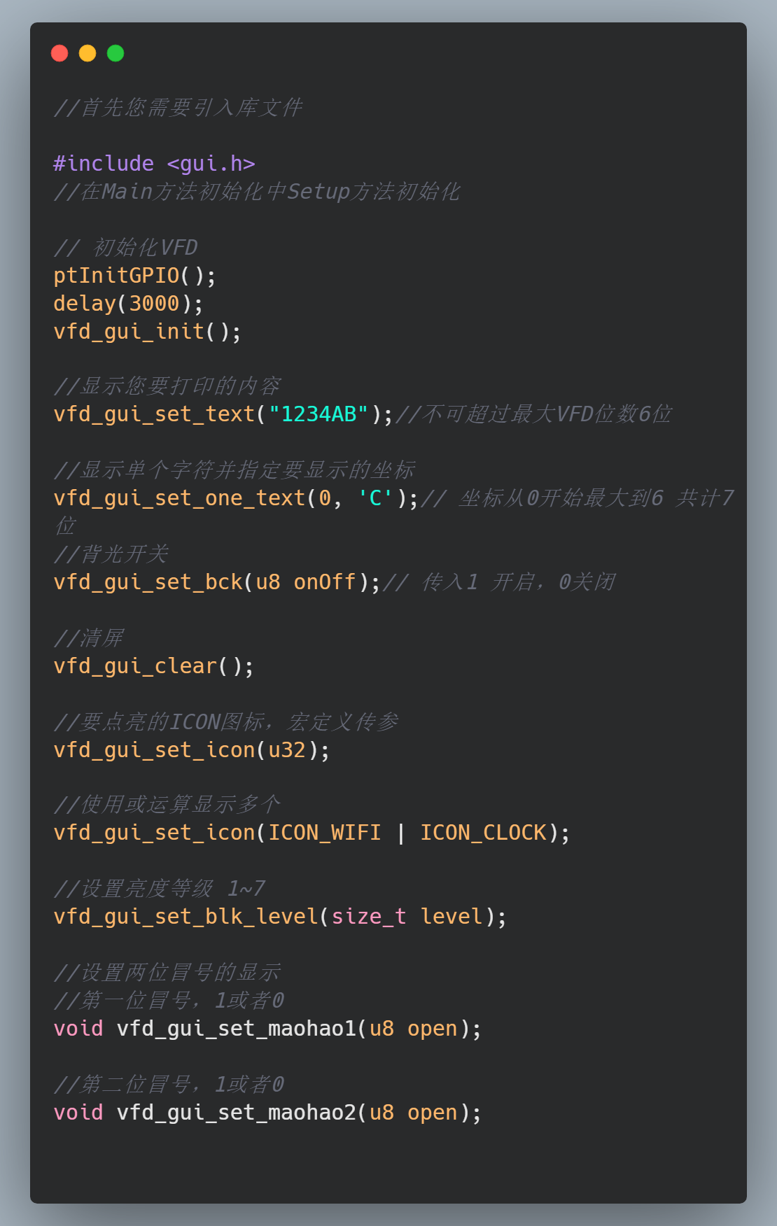
Open-source GitHub link: https://github.com/ccy-studio/CCY-VFD-7BT317NK
Discussion group: 676436122, Blog: saisaiwa.com
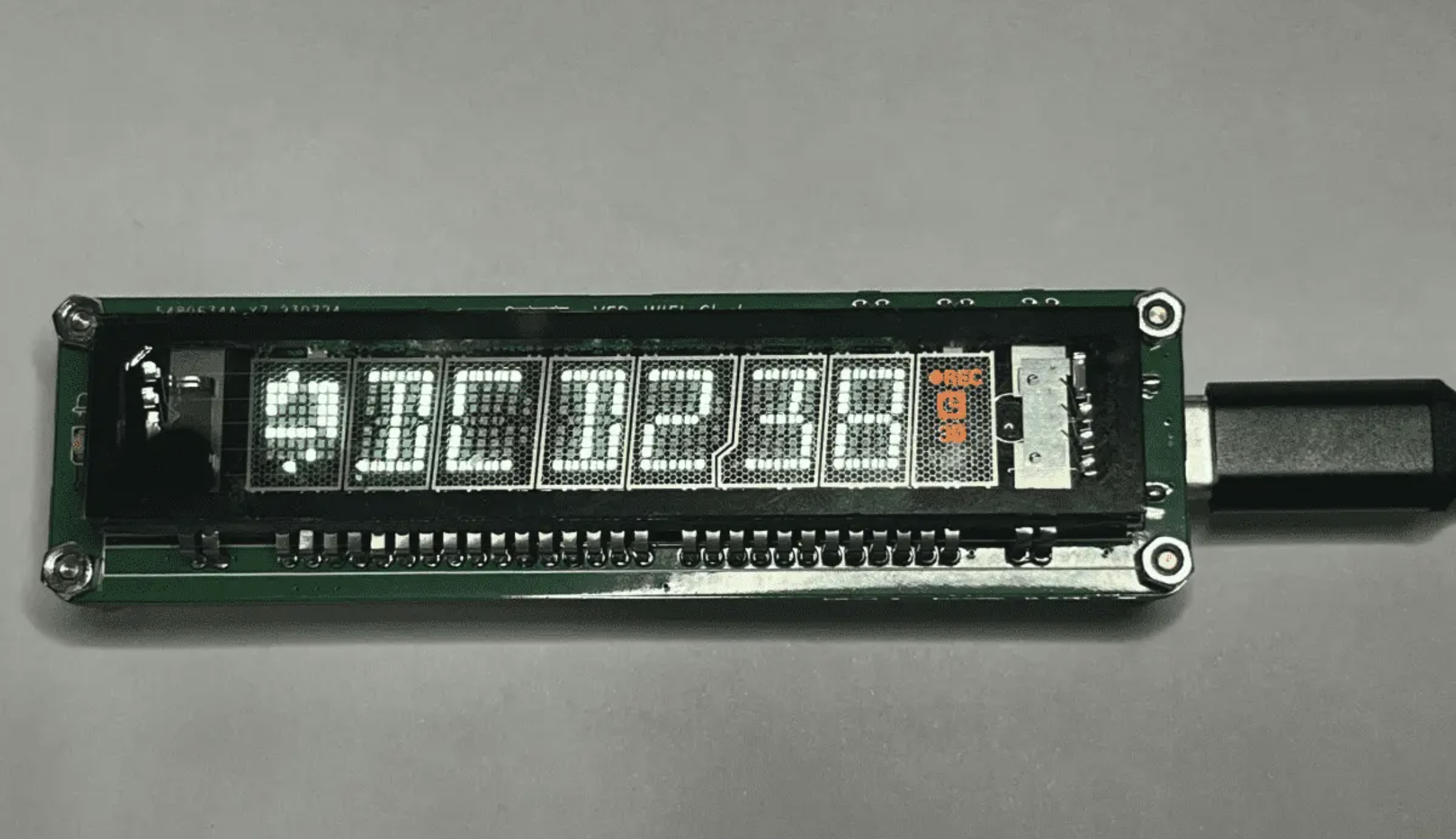
The actual display effect is very delicate and clear. Videos and images, after uploading and compression, do not display as well as expected.


IMG_2203.mp4
PDF_VFD 7-BT-317NK WIFI Clock.zip
Altium_VFD 7-BT-317NK WIFI Clock.zip
PADS_VFD 7-BT-317NK WIFI Clock.zip
BOM_VFD 7-BT-317NK WIFI Clock.xlsx
91493
V2 version VFD 7-BT-317NK WIFI clock
VFD Desktop Clock (7-BT-317NK) Second Improved Version (
Original First Version): https://oshwhub.com/yc_chen/vfd-317nk-qu-dong-ban
--> For driver scheme and MCU selection introduction, soldering precautions, and inspection steps, please refer to the first version of the content:
https://oshwhub.com/yc_chen/vfd-317nk-qu-dong-ban
Version
V1
initial VFD design sketch, functionality not perfect, feasibility verified in the fastest time online,
and cost kept under 10 yuan.
Disadvantages: poor stability, power supply issues, does not support PD charging head, sloppy PCB design.
V2
improved VFD design sketch, fixing known bugs in V1 and enhancing stability.
1. Improved stability by optimizing the power supply scheme and adding many capacitors.
2. Removed unnecessary AHT20 pads and improved PCB design. Added DC-DC power supply scheme, overall cost still controllable at around 9-13 yuan.
3. Compared to the four-layer board with green solder mask in V1, the improved V2 uses a double-sided board with black and green solder mask as the main color scheme.
The source code
version V1 has been released as release-V1.0. Download history: https://github.com/ccy-studio/CCY-VFD-7BT317NK/releases/tag/V1.0.
For newer versions, if no release is available, the latest version (v2) is still on the master branch: https://github.com/ccy-studio/CCY-VFD-7BT317NK
. The code is concise and easy to understand; API calling methods can be found in the Readme. It has high portability and is easily ported to 51 and STM32 microcontrollers.


IMG_2234~1.mov
PDF_V2 version VFD 7-BT-317NK WIFI clock.zip
Altium_V2 version VFD 7-BT-317NK WIFI clock.zip
PADS_V2 version VFD 7-BT-317NK WIFI clock.zip
BOM_V2 version VFD 7-BT-317NK WIFI clock.xlsx
91494
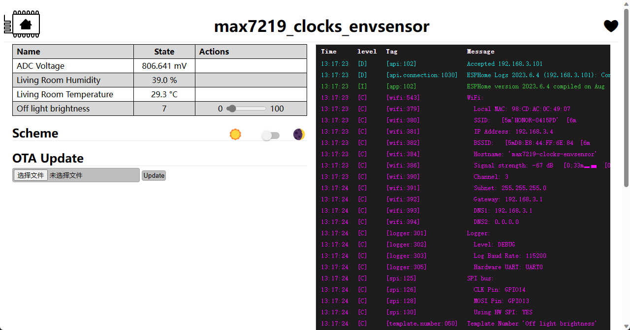
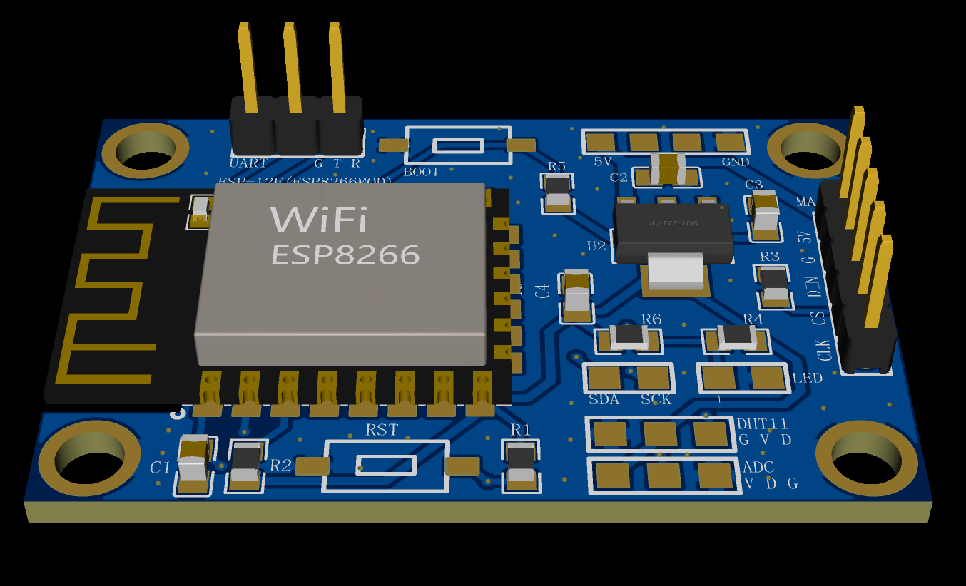
esp8266_max7219
Controlling an 8x32 dot matrix screen driven by a MAX7219 using an ESP8266 (
August 5, 2023): Firmware rewritten using ESPHOME. Supports ambient light brightness testing, temperature and humidity data acquisition, and a web server backend. Direct integration with HomeAssist is also supported.
This system uses an ESP8266 to control an 8x32 dot matrix screen driven by a MAX7219, primarily for real-time time display. The program is configured to turn off the display at night.
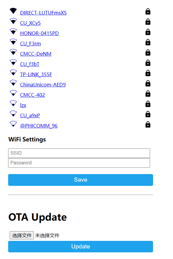
The program includes a built-in web configuration page. In AP configuration mode, users connect to the AP hotspot generated by the ESP8266 and enter the Wi-Fi name and password in the web interface.
After connecting to Wi-Fi, the system obtains the real-time time via NTP and automatically synchronizes the time every hour.
The firmware supports OTA upgrades; the ESP8266 obtains a new firmware version every hour and automatically upgrades.
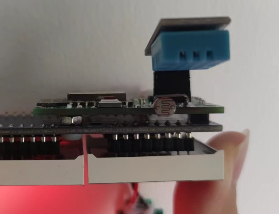
The PCB has reserved interfaces for DHT11, IIC, ADC, and LEDs.
The ESP8266 program code is open-sourced on Gitee: https://gitee.com/norep/esp8266_dev/tree/master/homeassistant/max7219_watch
August 5, 2023:
The firmware was rewritten using ESPHOME. It supports ambient light brightness testing, temperature and humidity data acquisition, and a web server backend. Web configuration allows direct access to HomeAssist.
The ambient light threshold can be configured in the backend to control the display to turn off when the ambient light falls below a certain value (mainly for automatically turning off the display after sleeping at night).
Connect the DHT11 according to the pre-reserved points on the board. Connect the photoresistor to the pre-reserved AD monitoring point on the board, and connect the photoresistor between the ADC point and VCC. Use a 1K resistor between the ADC point and GND.
The firmware supports web-based network configuration. After power-on, an AP hotspot is generated. After connection, it automatically redirects to or accesses 192.168.4.1 for network configuration.
SSID: "Esp8266-Max7219"
PASS: "12345678".
API key: "j7aB82C0NIV17VhlRdU9Zr7L16FJClXz3e+PAF/FnXo="
OTA password: "76708a3e9c495ebc07038212943d44a2"
Attached firmware: (Choose one)
esphome_format.bin: Use the esphome web tool to flash
legacy_format.bin; Use another flashing tool to flash.

esphome_format.bin
PDF_esp8266_max7219.zip
Altium_esp8266_max7219.zip
PADS_esp8266_max7219.zip
BOM_esp8266_max7219.xlsx
91495
Class D power amplifier (TPA3116 Type-C powered)
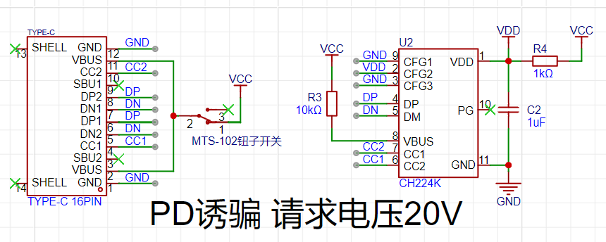
The NE5532+TPA3116 Class D amplifier uses a convenient Type-C power supply (onboard PD spoofing), meaning a Type-C phone charger supporting PD fast charging can be used as a power source (no need for an external power adapter!). I personally tested it and the sound quality is excellent.
The
Type-C interface provides power, supporting PD fast charging (chargers that support brand-specific fast charging protocols are generally compatible with PD fast charging). The Type-C charger itself is the power cable, making it very convenient
for PD charging of the CH224K solution. It requires 20V. The preamplifier
uses the NE5532 op-amp, offering excellent value for money, and the sound quality is sufficient for most needs (except for audiophiles).
The core amplifier is the Texas Instruments TPA3116, supporting a maximum of 2*50W. The PWM frequency is selectable (higher frequencies result in better treble performance but significantly increase power consumption and heat generation).
Both audio input and output use 3.5mm audio jacks (AUX interfaces). Since the audio output directly shorts the left and right... The negative terminal of the channel may prevent dual-channel output (mono output is perfectly fine).
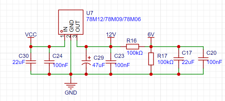
Unless otherwise specified, all resistors and capacitors are packaged as 0805. The power supply section
is detailed below. It uses a 16-pin Type-C connector (this requires skilled soldering, but can be easily done with solder paste and a hot air gun). The CH224k solution is used to trick PD fast charging, requesting 20V (the maximum voltage of the PD protocol) to ensure sufficient power. Note: It is recommended to use a 65W or higher charger that supports PD fast charging; otherwise, you may experience blurry sound quality or various problems due to insufficient power. The preamp uses a 3.5mm audio input interface (AUX interface), and the author used a PJ-316 connector. After the signal input, a dual RV097 potentiometer is used to divide the voltage and adjust the signal strength. For the coupling capacitors (C5, C15), the author used Epcos 1uF MKP capacitors (5mm lead pitch). Personally, I think the sound quality is almost identical to that of Weima MKP capacitors, but Epcos MKP capacitors are much cheaper (less than ¥1 each in some cases), making them a cost-effective choice. Of course, those seeking the ultimate sound quality can replace the capacitors with higher-end ones. The preamplifier uses the classic NE5532 op-amp, with a preamplification factor of 3x. The op-amp and amplification factor can be changed according to needs (the author used a dual op-amp package; the first op-amp is used for amplification, and the second op-amp is configured as a voltage follower for buffering and adjusting input/output impedance). The op-amp power supply uses the 78Mxx series; theoretically, 78M12/78M09/78M06 can be used. However, considering that the maximum voltage of the TPA3116's audio input pin is 6.3V, it is recommended to use 78M09 or 78M06 for safety (the author used 78M09). The bias voltage of the signal input to the TPA3116 is approximately half of the regulated value (through voltage division via R16 and R17). Additionally, C29 is a surface-mount aluminum electrolytic capacitor (6.3*5.4mm), and the core amplifier (single chip) is a Texas Instruments TPA3116(D2). It has high internal integration and a relatively simple peripheral circuit; the reference circuit in the datasheet is almost entirely copied. It defaults to a 400kHz PWM frequency, resulting in acceptable treble quality and excellent mid and bass. The second version will adjust the PWM frequency to be adjustable to improve treble quality. (The author's skill and budget are limited; audiophiles please refrain from criticism.) The coupling capacitors (C6, C12, C16, C19) still use Epcos 1uF MKP capacitors (5mm lead pitch). The author used a mobile phone charger as the power supply, resulting in relatively low ripple. Power filtering using two 1000uF high-frequency electrolytic capacitors and four small ceramic surface-mount capacitors is sufficient. Furthermore, the negative terminal of the audio output is isolated from the power ground (GND), and no audible power noise was detected in actual testing. (The pursuit of ripple is endless. The author's skill and budget are limited; please refrain from criticism if you have extremely high requirements for power supply ripple.) Regarding heat: The author tested in a summer room without air conditioning (temperature 30°C+), the amplifier got hot after a few minutes of use (estimated temperature 40~45°C), and the inductor got slightly warm, but nothing serious. It is recommended to use a heatsink (currently, a 10mm*10mm heatsink is usable in version V1.0; the second version will expand the space around the chip to accommodate larger heatsinks). For filtering and output , refer to the official datasheet. The output still uses a 3.5mm audio jack (AUX interface). When connecting speakers, select the appropriate adapter cable (e.g., 3.5mm to RCA) based on the speaker's input interface. The output inductor is a CDRH127 10uH power inductor. During testing, it became slightly warm (in summer, without air conditioning, at 30°C+), but this did not affect normal use. The author directly shorted the negative terminals of the left and right channel outputs, which may cause a failure to output stereo sound (the author's usage scenario was a single mono speaker). Mono output worked perfectly. If stereo is required, you can modify the wiring or change the output interface (e.g., change to RCA connectors for the left and right channels respectively). The stereo issue will be resolved in version 2 (V2.0). ** Important Note:** The Type-C power supply must support PD fast charging! And the power output should ideally be above 65W! Otherwise, it will not work properly or the effect will be extremely poor!


Actual product illustration.jpg
PDF_Class D Power Amplifier (TPA3116 Type-C Powered).zip
Altium Class D Amplifier (TPA3116 Type-C Powered).zip
PADS Class D Power Amplifier (TPA3116 Type-C Powered).zip
BOM_Class D Amplifier (TPA3116 Type-C Powered).xlsx
91496
electronic

 Schematic and PCB Design:
 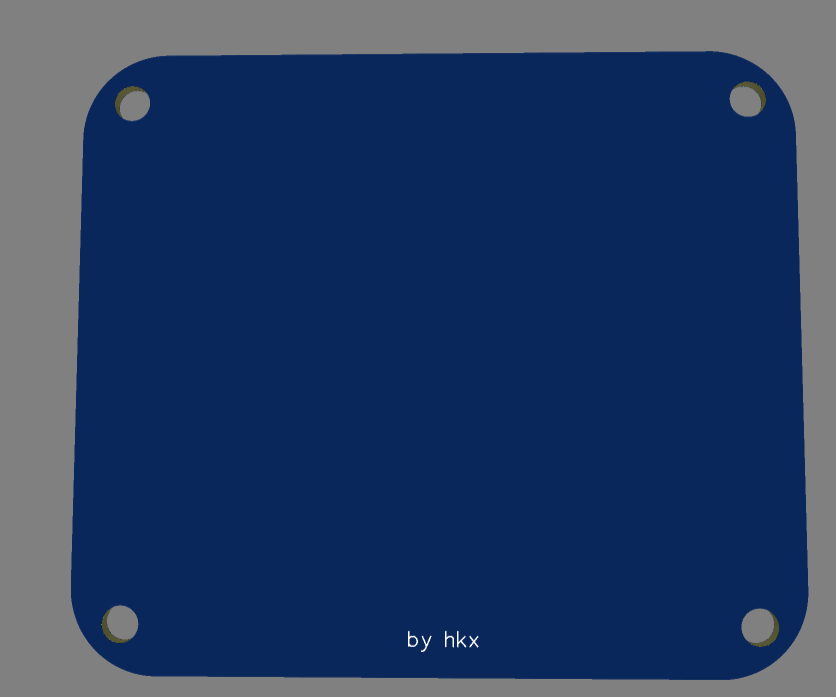 Topboard,
 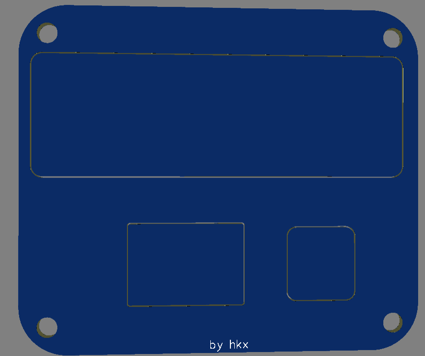 Schematic,
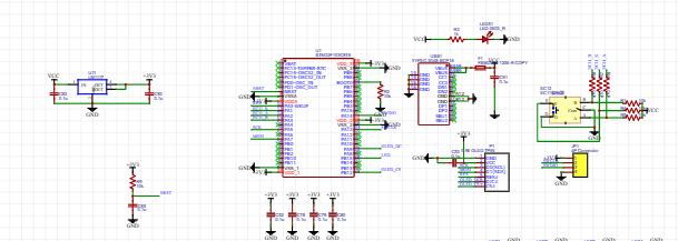
 PCB.
PCB. 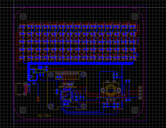 Program Download


 京公网安备 11010802033920号

 PCS240DL-1


