A digital oscilloscope is an instrument used to display electrical signal waveforms. It mainly consists of analog front-end processing circuits, microcontroller circuits, power supply circuits, control circuits, trigger circuits, calibration circuits, and other circuits.
This training camp uses a GD32 as the main controller (fully compatible with STM32F103C8T6) for DAC sampling and output of signals.
1. The power module
uses a 3.7V lithium battery and a Type-C port for power supply. A power switching circuit switches between Type-C and lithium battery power. The voltage is then boosted by a PW5100 chip before powering other components.


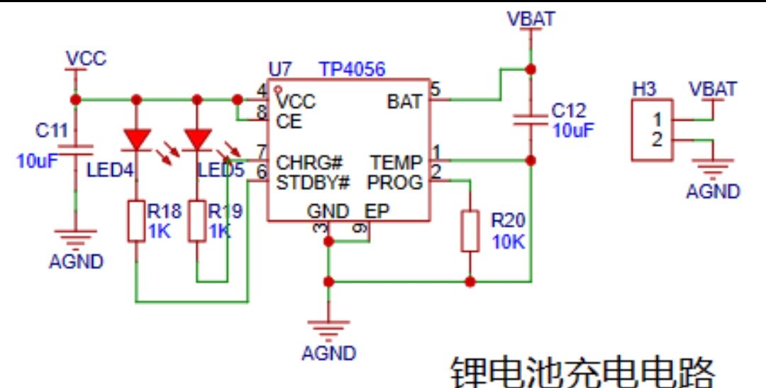
The lithium battery charging circuit uses a TP4056 to charge the battery. Two indicator lights monitor the battery level: a green light indicates charging is complete, and a red light indicates charging is in progress. In addition to the power input circuit,
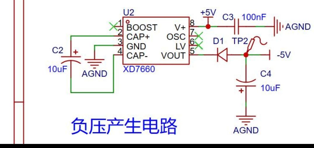
the negative voltage generation circuit
uses the XD7660 negative voltage generator to obtain a negative voltage to ensure the operational amplifier's performance in measuring negative voltages. This chip has a simple external circuit, requiring only two capacitors and a diode to operate. Theoretically, with an input voltage of +5V, it can also output a -5V voltage. Due to the chip's internal voltage drop and conversion efficiency, the actual measured negative voltage is approximately -4.3V, which still meets the operational amplifier's requirements.
2. The analog front-end processing circuit
includes an input AC/DC coupling switching circuit, an input signal attenuation circuit, and a signal conditioning circuit.
AC/DC coupling switching circuit: A 100nF capacitor is used to block the DC component. The higher the frequency, the smaller the capacitor should be; 100nF is sufficient here. For capacitor selection, please refer to relevant documentation.
Signal attenuation circuit: When measuring high voltage, the board cannot withstand it, so voltage attenuation is necessary. Here, the voltage is attenuated by 1/50. This allows us to calculate that the low-voltage range can measure -1.6~+5V, and the high-voltage range can measure -80V~+250V. Since there is no protection, it's best to avoid measuring high voltage for safety reasons. You can also change the attenuation factor by replacing the resistor.
Signal conditioning circuit: This involves analog electronics knowledge and can be analyzed using the concepts of "virtual short" and "virtual open". A voltage follower (impedance matching) and a proportional amplifier circuit are added after this, resulting in Vo = (5-Vin)/2.

3. Comparator frequency measurement circuit:
The ADC input signal is compared with the input signal through a hysteresis comparator to achieve frequency measurement.
To enhance the circuit's anti-interference capability, positive feedback is introduced on top of the single-limit comparator to ensure signal stability within a certain range. After passing through the hysteresis comparator circuit, a square wave signal is output. The period of the input waveform is calculated using the microcontroller's timer capture function.

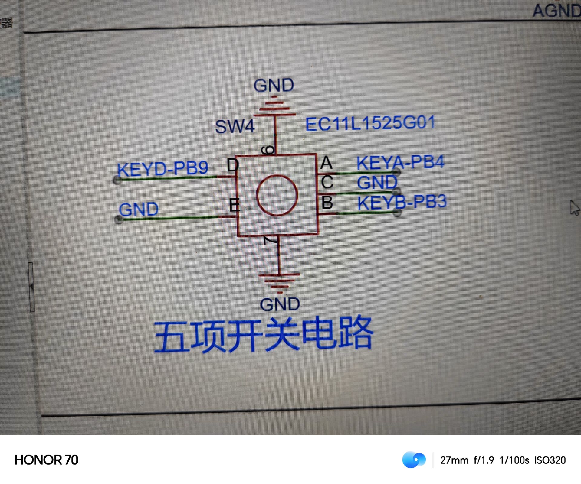
4. Rotary Encoder Circuit: A
rotary encoder is a special type of button. The EC11 rotary encoder used in this project has five pins. Pins D and E are similar to ordinary button pins; they conduct when pressed and disconnect when released. The remaining three pins, A, B, and C, are used to detect the rotation direction of the knob. Pin C is the common terminal and can be directly grounded.
During rotary encoder operation, there is a phase difference between the A and B signal pins. That is, a change in the signal on one pin occurs before the signal on the other pin changes, meaning the two pins do not change simultaneously. By detecting which pin changes first, the clockwise or counterclockwise rotation function can be determined.
The rest of the circuit is relatively simple and will not be described in detail here.
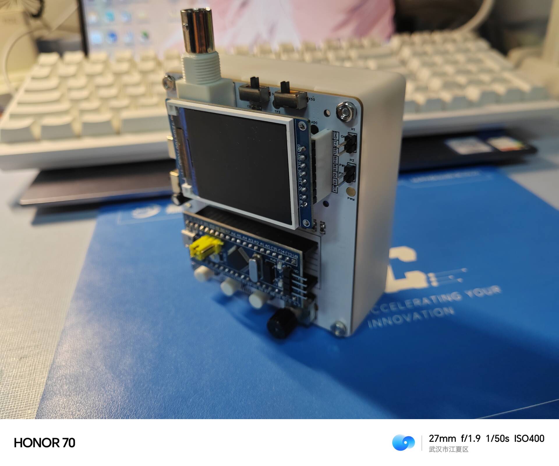
Next, let's look at the actual finished product .


After measurement, the square wave bandwidth can reach 30~50KHz, making it a good measurement tool.
You can view the effect through a video.
The GD32 and STM32 source code and HEX files, as well as the BIN file, are all included below. If the GD32 software crashes when burning the HEX file, try using the BIN file instead. STM32 serial programming can be done using FLYMCU.


 京公网安备 11010802033920号

 HDSP-A213-DH000


