The design was inspired by
the STC Microcontroller Creative Design Competition held by JLCPCB. Wanting to learn and learn for free (mainly free), I entered the competition and designed this development board . The core control unit
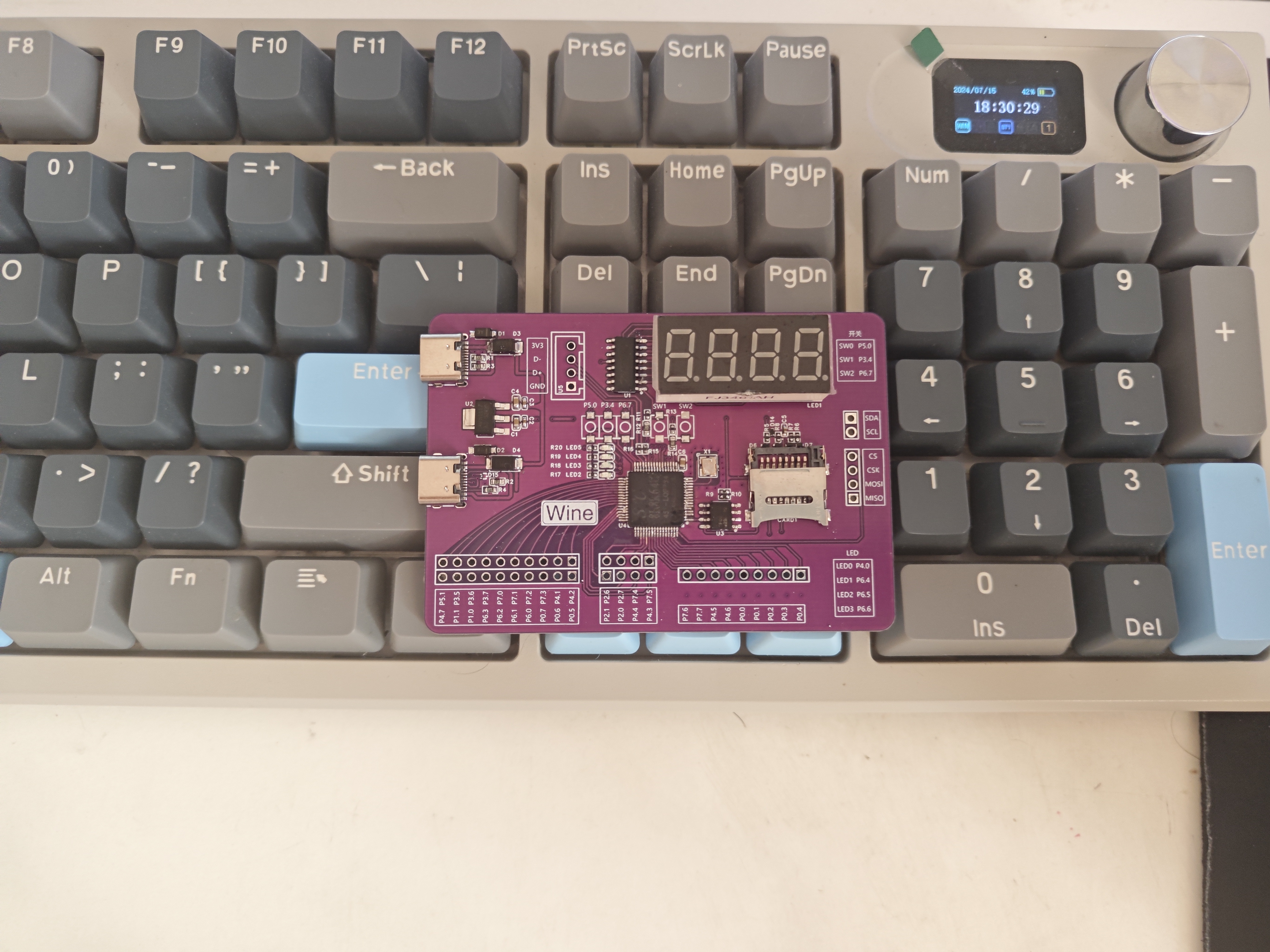
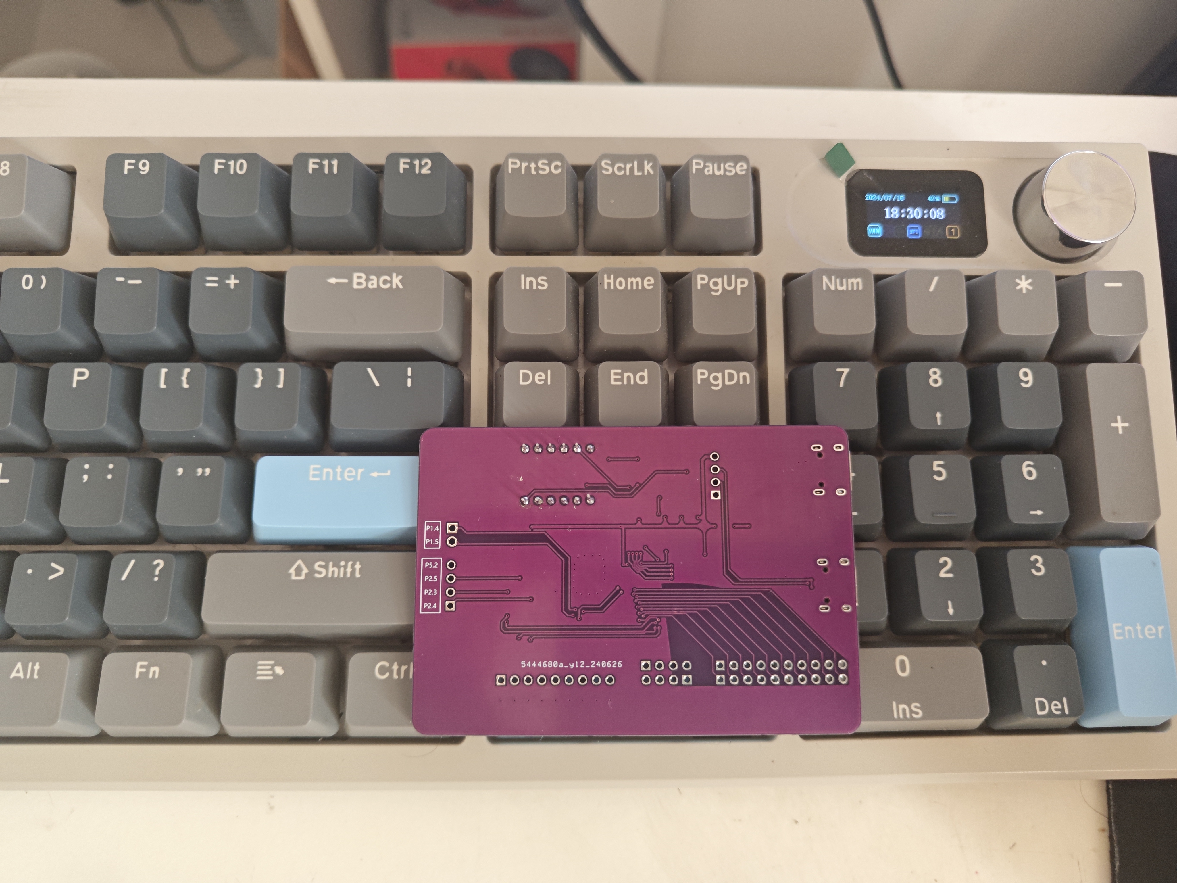
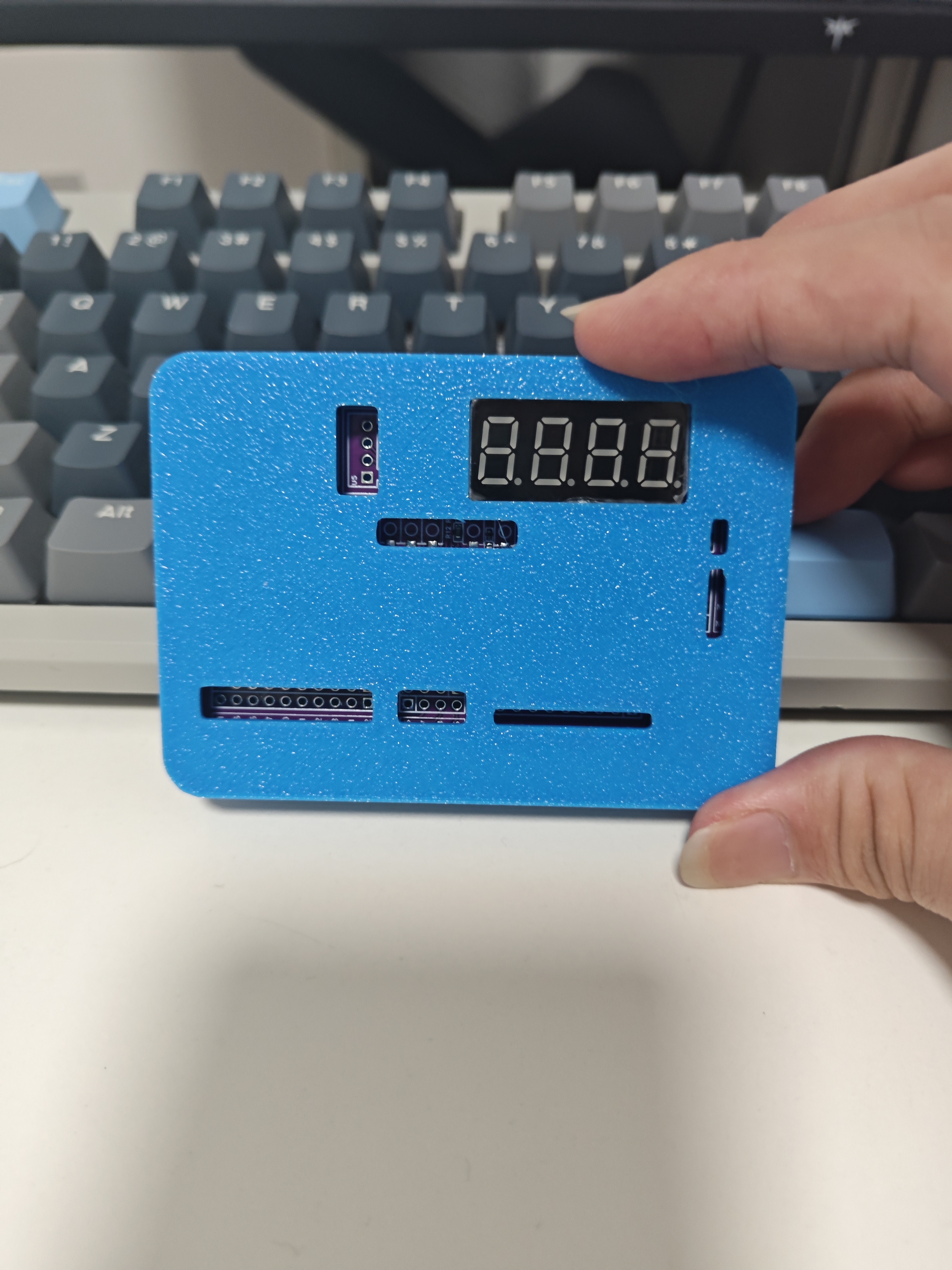
of the hardware peripherals is the STC8H8K64U in a high-performance LQFP-64 package. It boasts high integration, eliminating the need for external crystal oscillators and reset circuits, simplifying circuit design. ADC performance: It features a built-in 12-bit high-precision ADC with 15 input channels to meet diverse analog signal acquisition needs. Voltage adaptability: It supports an ultra-wide operating voltage range of 1.9V to 5.5V, enhancing system environmental adaptability and stability. Timer and communication interface : Timer resources: Equipped with five 16-bit timers, providing rich timing/counting functions to meet the needs of precise time control and complex timing tasks. High-speed serial port: Integrated with four high-speed serial ports (UART/USART), supporting high-speed data communication for easy information exchange with external devices or systems. PWM and DMA : PWM control: 8 channels/2 groups of advanced PWM outputs support complex waveform generation and control, suitable for scenarios such as motor drive and LED brightness adjustment. DMA Support: The ADC is equipped with DMA functionality, enabling CPU-free transmission of 15 channels of high-speed ADC data, improving data processing efficiency and system response speed. USB Connectivity and Programming: Supports full-speed USB 2.0/USB 1.1 communication for easy connection to PCs or other USB devices. Download and Simulation: Supports program download and online simulation via USB and ISP, improving development efficiency and debugging convenience. GPIO and Peripheral Interfaces: 43 general-purpose input/output pins (GPIO) provide flexible interface expansion capabilities. Integrated Peripheral Interfaces: Built-in I2C and SPI interfaces (multiplexed via GPIO), supporting multiple communication protocols and standard peripheral connections. LEDs and Buttons: 4 LEDs and 3 buttons (all pulled up to 3.3V) are pre-installed for status indication and user interaction design. TF Card Slot: Built-in TF card slot, sharing I/O with the SPI interface for easy data storage and expansion. Digital Display: Integrated 4-digit 7-segment common cathode digital display, connected to the driver circuit via a single I/O, simplifying display control. Power and Interface Protection : Power Input: Equipped with two TYPE-C interfaces, one for power supply only, and the other for both power supply and connection to the MCU, meeting the needs of various usage scenarios. Anti-static Design: Both the TYPE-C interface and the TF card slot are equipped with TVS (Transient Voltage Suppressor), effectively preventing electrostatic damage and improving system reliability. Housing: The housing model can be exported as a 3D model from EDA and printed on a JLCPCB 3D printer. Physical demonstration and instructions: The switch was purchased incorrectly, so it wasn't soldered. Soldering Precautions : Prioritize soldering surface-mount components, then solder through-hole components. The soldering order is from low to high: First, solder the LED and its adjacent resistor, then the button and its adjacent resistor, then the capacitor and crystal oscillator next to the MCU , then the EEPROM and its adjacent resistor , and finally the MCU. Soldering the MCU first is because prolonged high temperature heating could damage it if it were soldered first. After the MCU is finished, solder the resistor, capacitor, and TVS next to the TF card slot, then the TF card slot, and finally the TYPE-C and LDO sections. The only suggestion here is to solder R1-R4 last, and solder all the others first. For the remaining components, solder them as conveniently as possible. Demonstration video will be added later.


 京公网安备 11010802033920号

 PLT0805Z2131AST5


