* 1. Project Function Introduction
This project is the design of a desktop thermometer and hygrometer. Its main function is to detect ambient temperature and humidity, and it can be set to provide temperature and humidity alerts. When the ambient temperature and humidity exceed the set values, the thermometer and hygrometer will issue an alert.
The project design concept is shown in Figure 1.

Figure 1 Overall Design Concept of Desktop Thermometer and Hygrometer The
functional modules are mainly divided into seven modules: temperature and humidity acquisition, temperature and humidity display, date and time display, battery power detection, temperature, humidity and battery alarm, low power mode, and temperature and humidity recording. A brief analysis of each of these seven modules is provided below.
1.1 Temperature and Humidity Acquisition
This project uses the Sensirion SHT40 temperature and humidity sensor. This sensor is small in size, high in accuracy, and easy to wire, making it very suitable for this project.
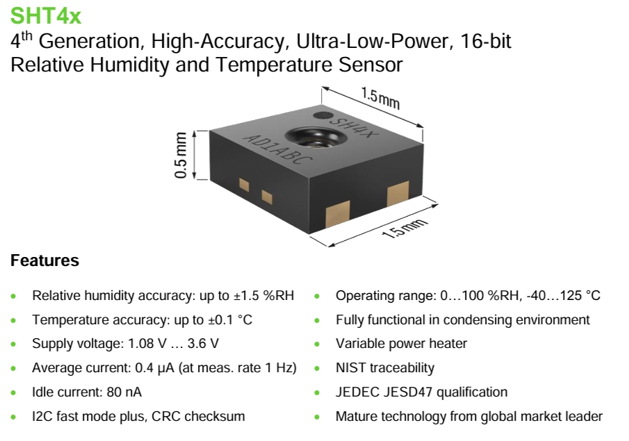
Figure 2 Introduction to Sensirion Sensors
1.2 Temperature and Humidity Display
This project plans to use two display methods: one is to use two three-digit LED displays, one showing the temperature value and the other showing the humidity value. This display is very intuitive. Another option is to use a 0.96-inch OLED display. This is because OLED displays offer richer content compared to digital tubes, and it also allows for human-machine interaction in conjunction with buttons, enabling functions such as setting temperature and humidity alarm limits, displaying date and time, and displaying alarm information.
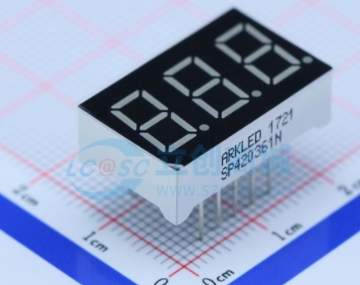
(Figure 3: Digital Tube;

Figure 4: 0.96-inch OLED Display
) 1.3 Date and Time Display and Battery Power Detection
The main control chip used in this project is the STM32G030K6T6. The date and time can be read using the chip's built-in TCR clock and displayed on the OLED screen.
This project uses two AA batteries connected in series (resulting in 3V) to power the system. The battery voltage is detected by the STM32G030K6T6's ADC to determine the battery power.
1.4 Temperature, Humidity, and Battery Alarms:
Through a human-machine interface formed by buttons and an OLED display, the operator can input upper temperature, upper humidity, and lower battery limits. The alarm is judged by comparing these limits with collected temperature, humidity, and battery levels. If the set alarm values are exceeded, the main controller controls the LED to flash and the buzzer to sound (which can be turned on or off in the settings), and displays the alarm information on the OLED display.
1.5 Low Power Mode :
This project plans to design three operating modes:
Low Power Mode: No information is displayed; the system enters sleep mode.
Normal Mode: OLED display, digital tube does not display.
Highlight Mode: OLED and digital tube display simultaneously.
1.6 Temperature and Humidity Recording:
This function is an extension function, with a reserved AT24C64 memory chip. It can be designed to store daily temperature and humidity data, with the storage time and frequency set. The hardware is reserved; the program will be developed as needed.
*2. Project Attributes:
This project is the first public disclosure by an individual. The principle design references the official schematic diagram from the LCSC training camp, the PCB design is self-designed, and the program is adjusted based on the LCSC training camp program to achieve the self-designed functions.
* 3. Open Source License
GPL 3.0
* 4. Hardware Section
4.1 Circuit Principle Design
The hardware section mainly consists of 11 parts: power supply circuit, main control circuit, crystal oscillator circuit, temperature and humidity sensor, digital tube display circuit, button circuit, LED circuit, buzzer driver circuit, OLED display circuit, EPROM driver circuit, and IO interface circuit.
4.1.1 Power Supply Circuit:
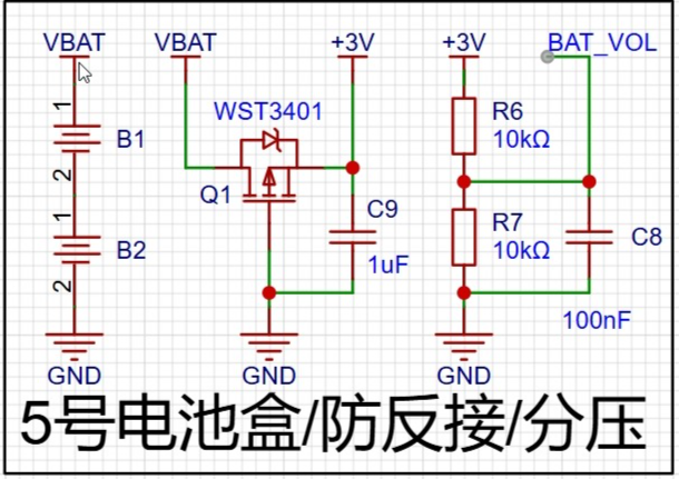
Figure 5 shows the power supply circuit
system, which is mainly powered by a 3V voltage obtained from two AA batteries connected in series. After the voltage is output, a field-effect transistor is connected to prevent reverse voltage connection. Two 10K resistors are used to divide the voltage between 3V and ground. The ADC of the microcontroller is used to collect the voltage to determine the battery level.
4.1.2 Main Control

Circuit Figure 6 shows the main control circuit.
The main control chip is STM32G030K6T6. After the main power supply of 3V comes in, a ferrite bead is used to remove interference before powering the microcontroller.
4.1.3 Crystal Oscillator

Circuit (Figure 7)
: The STM32G030K6T6 has an internal crystal oscillator, but an external 32.768kHz crystal oscillator is used to obtain a more accurate clock signal.
4.1.4 Temperature and Humidity Sensor, OLED Display Circuit, and EPROM Driver
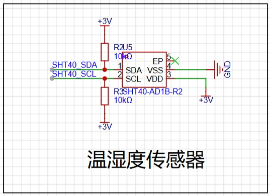
Circuit (Figure 8: Temperature Sensor

Circuit; Figure 9: 0.96OLED
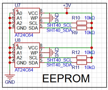
Circuit; Figure 10: EEPROM
Circuit): The temperature and humidity sensor, OLED display circuit, and EPROM driver circuit all communicate with the STM32G030K6T6 via I2C. Refer to the chip manual for connection instructions.
Note: The AT24C64 schematic shows two chips; only one chip should be soldered in actual use, with the other as a spare (address conflicts may occur).
4.1.5 Digital Tube Display
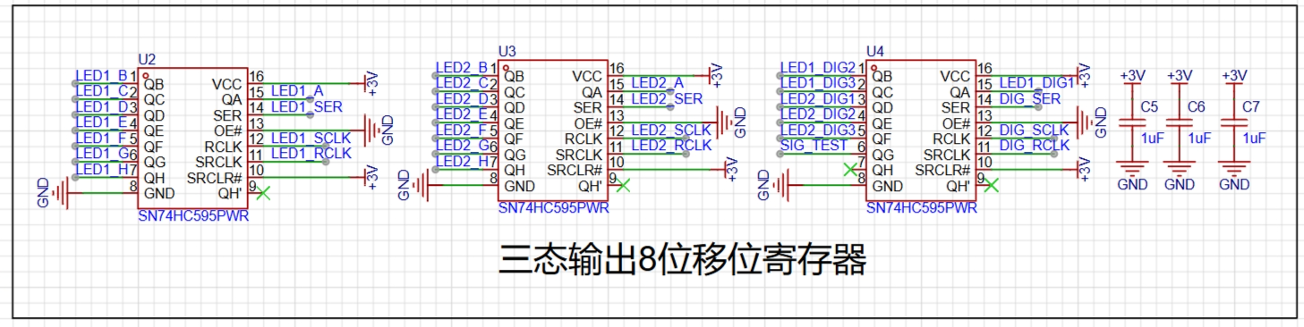

Circuit (Figure 11): The digital tube display circuit
uses two 3-digit common cathode digital tubes, controlled by an 8-bit shift register with tri-state outputs to reduce the I/O usage of the STM32G030K6T.
4.1.6 Button Circuit, LED Circuit, and Buzzer Driver
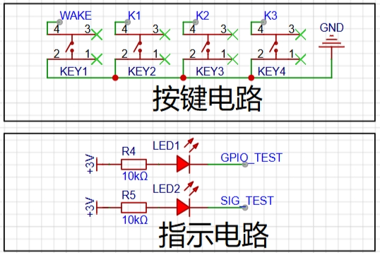
Circuit Figure
12)
The button circuit, LED circuit, and buzzer driver circuit are all simple IO high/low level control circuits. Refer to the schematic diagram and connect them to the STM32G030K6T's IO.
4.1.7 IO Interface
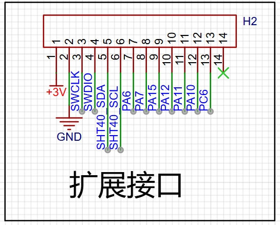
Circuit (Figure 14) The IO interface
brings out the unused IO ports of the STM32G030K6T for easy program download and expansion.
4.2 PCB Design
The PCB layout is shown in the figure below. The digital tube is placed on the right side of the circuit, the OLED display on the left, and the buttons at the bottom for easy operation.
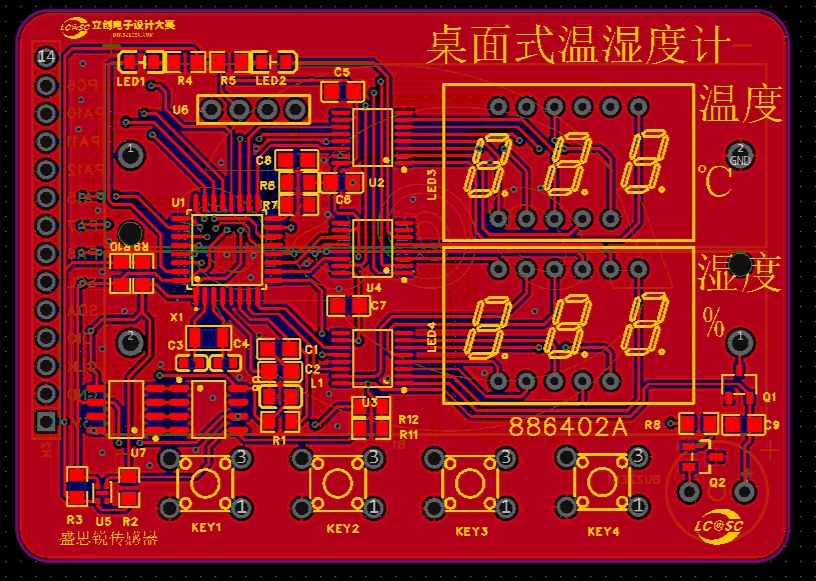
(Figure 15 PCB Layout)
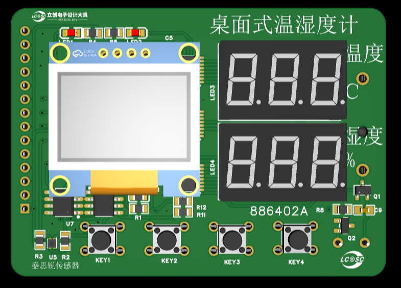
(Figure 16 Circuit 3D Model)
The temperature and humidity sensor uses a chip, which is relatively small and has some soldering difficulty. For replication, a module can be chosen for easier soldering.
4.3 PCB Prototyping
After the PCB design is completed, you can place an order with JLCPCB. We are very grateful to JLCPCB for providing free prototyping.
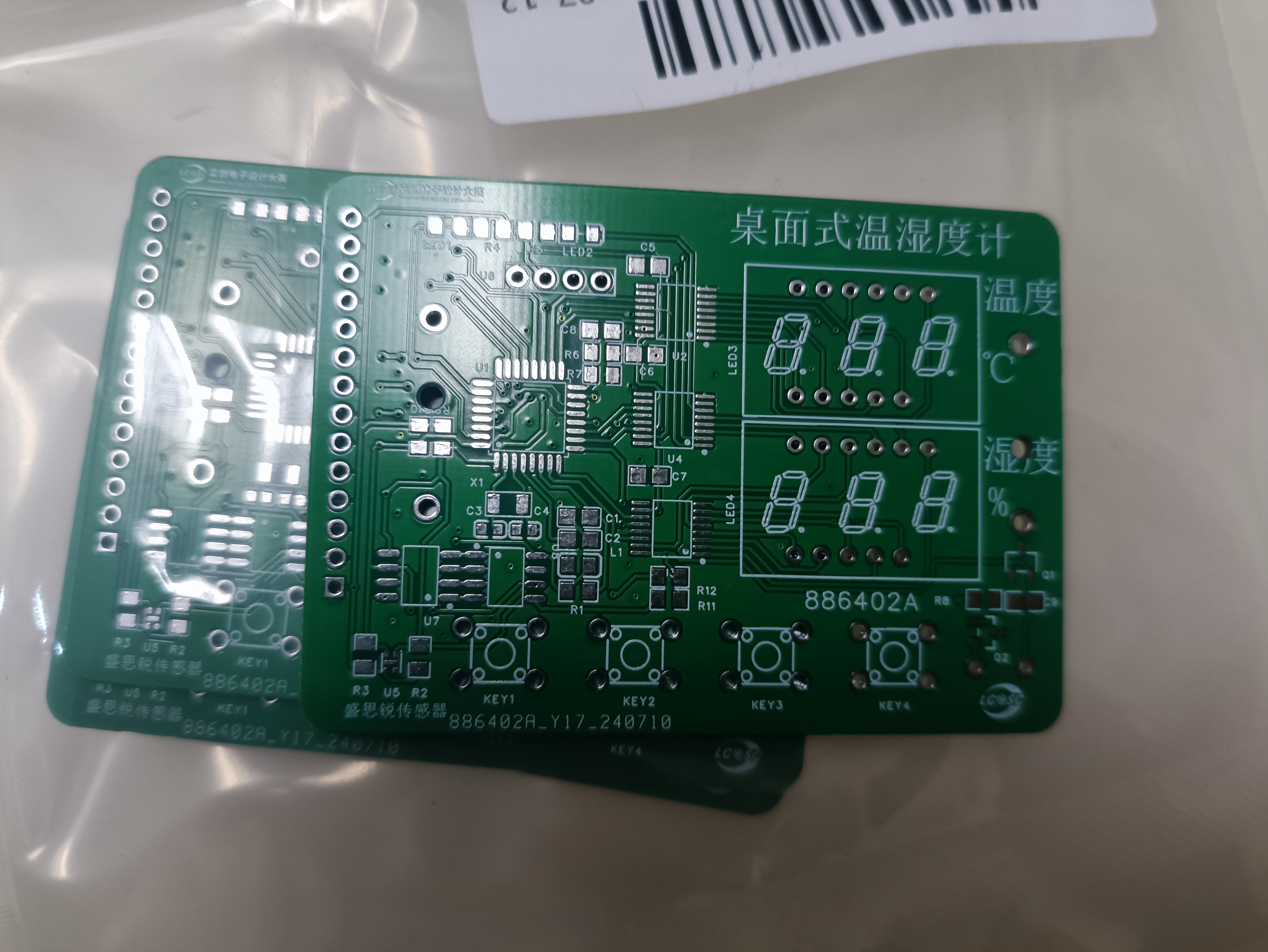
Figure 17 PCB Physical Image
4.4 Soldering
Students with 3D printing capabilities can export the PCB drawing as a DXF file, then stretch it in 3D design software (SolidWorks/Shapr 3D, etc.) to print it out as the PCB stencil.
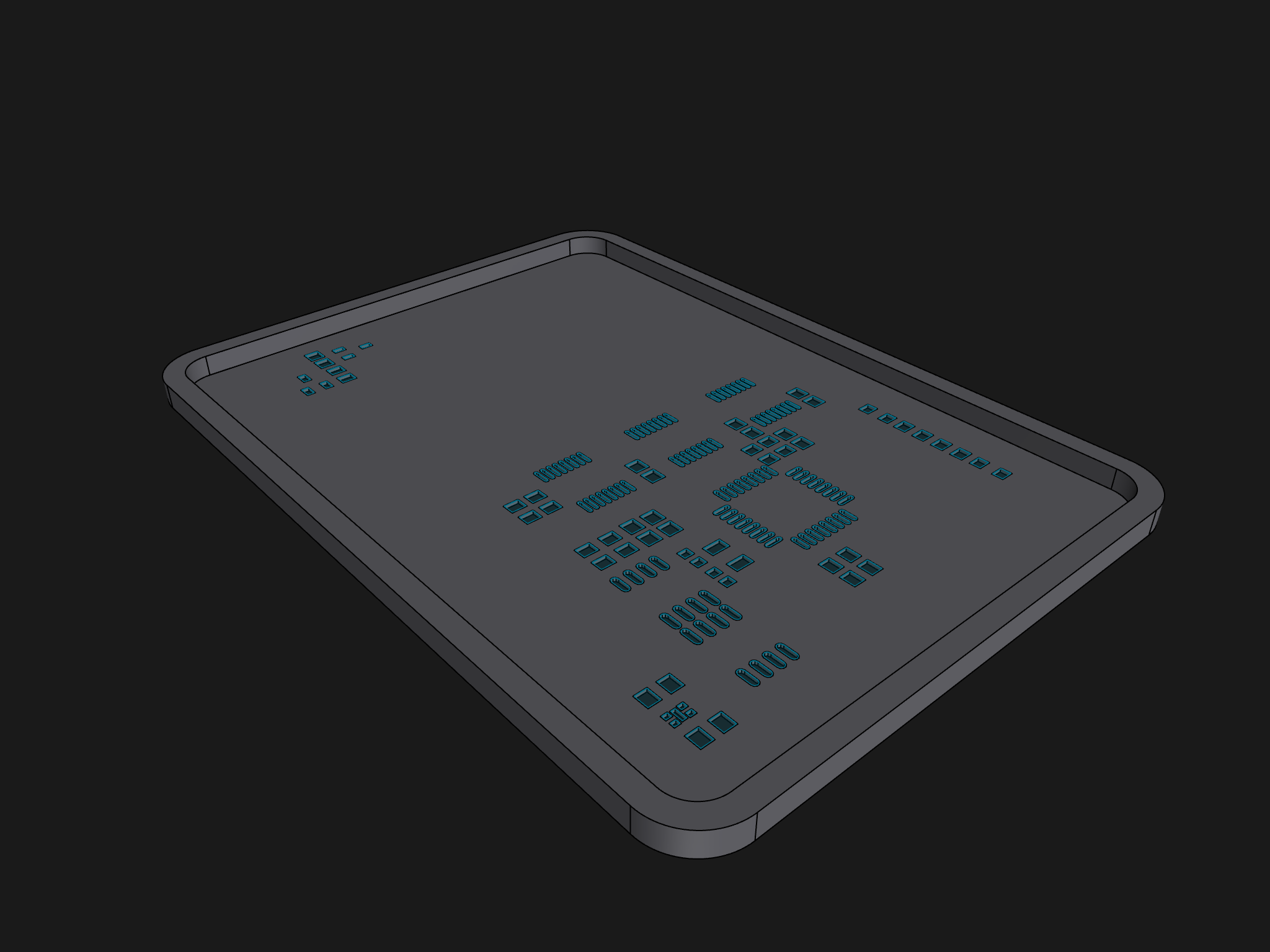
Figure 18 PCB Stencil Model

Figure 19 Soldering on the PCB
After installing the components, you can proceed to the soldering stage:
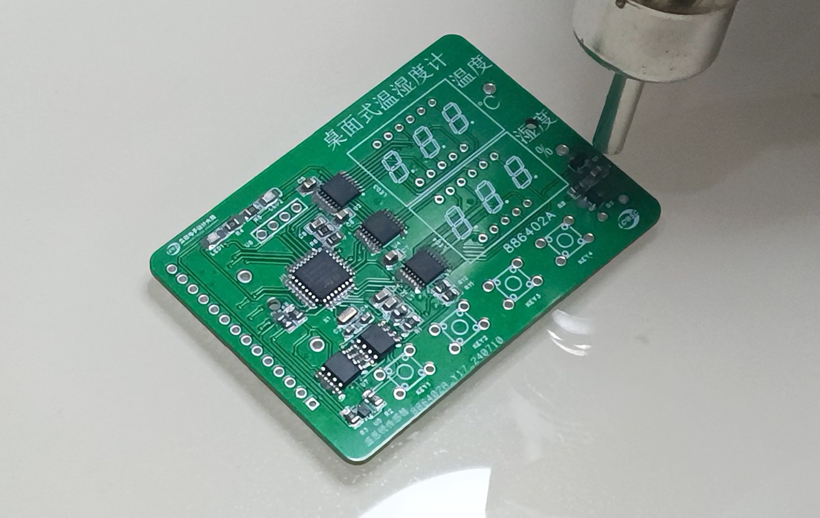
Figure 20 Soldering

Figure 21. Completed Welding Image
4.5 Housing Design The
housing design mainly considers the OLED display area, digital tube display area, button area, and temperature and humidity sensor area in conjunction with the PCB layout. See the following figures for the housing design:
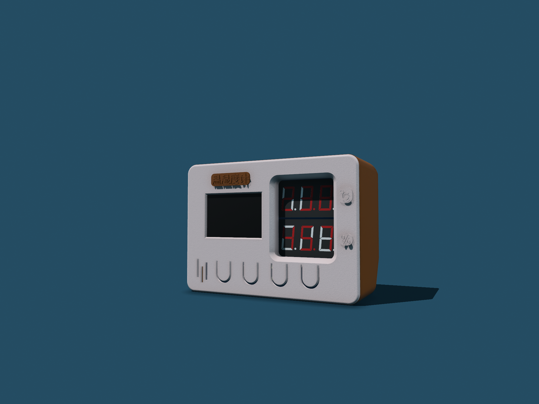
Figure 22. Housing Model Design Figure
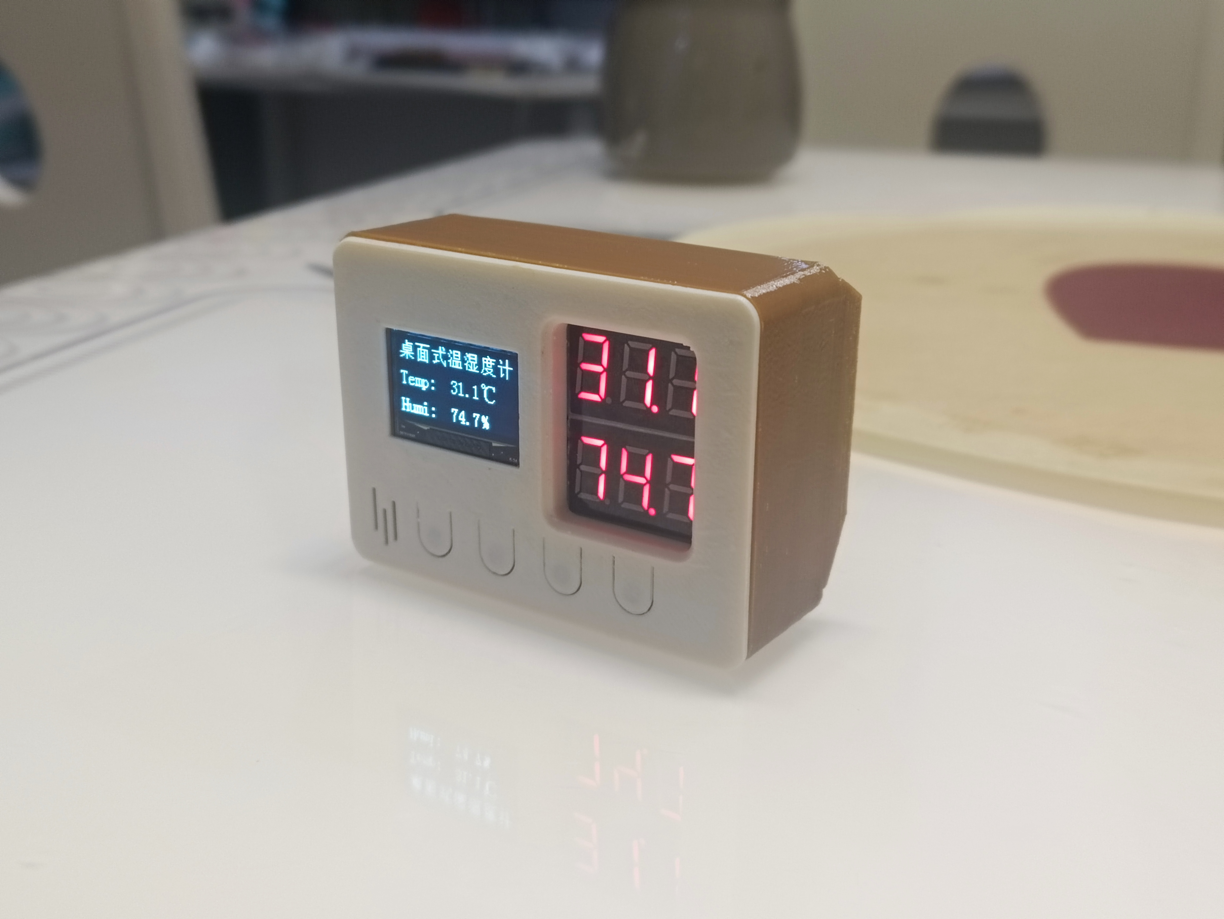
23. Housing Image
*5. Software Part
5.1 Design Idea
Based on functional requirements, the program part mainly aims to implement the following four functional modules:
temperature and humidity display (OLED display and digital tube display);
temperature and humidity alarm (temperature and humidity upper limit setting, alarm mode is LED flashing and buzzer beeping);
date and time display (the temperature and humidity meter is not connected to the network, and the date and time need to be manually calibrated);
mode settings (highlight mode, normal mode, low power mode).
The overall design idea is shown in the following figure:

Figure 24. Program Implementation Idea
5.2 Program Writing
The program writing mainly uses STM32CubeMX and Keil uVision5. Some configurations and programs are shown in the following figures. Detailed configurations and program code are in the attachment.

Figure 25. Chip Pin Configuration Diagram (Partial)

Figure 26. Program Code (Partial)
*6. BOM List
See the attached BOM list for details.
*7. Verification image of the competition logo
(Figure 27). A physical image of the circuit board containing the competition logo.
* 8. Demonstrate your project and record a video for upload
. See the attached demonstration video for details.


 京公网安备 11010802033920号

 L320ML01PI


