supports the 1.54-inch e-ink screens of Heze v1 and WaveSnow v2. It implements Chinese display, partial refresh, and global refresh.
The temperature and humidity sensor is sht31. Testing showed it wakes up every 3 minutes to update temperature and humidity; otherwise, it's in deep sleep mode, and the battery life is approximately one week (350mAh battery).
It supports Wi-Fi image upload and management, supporting JPG and BMP formats.
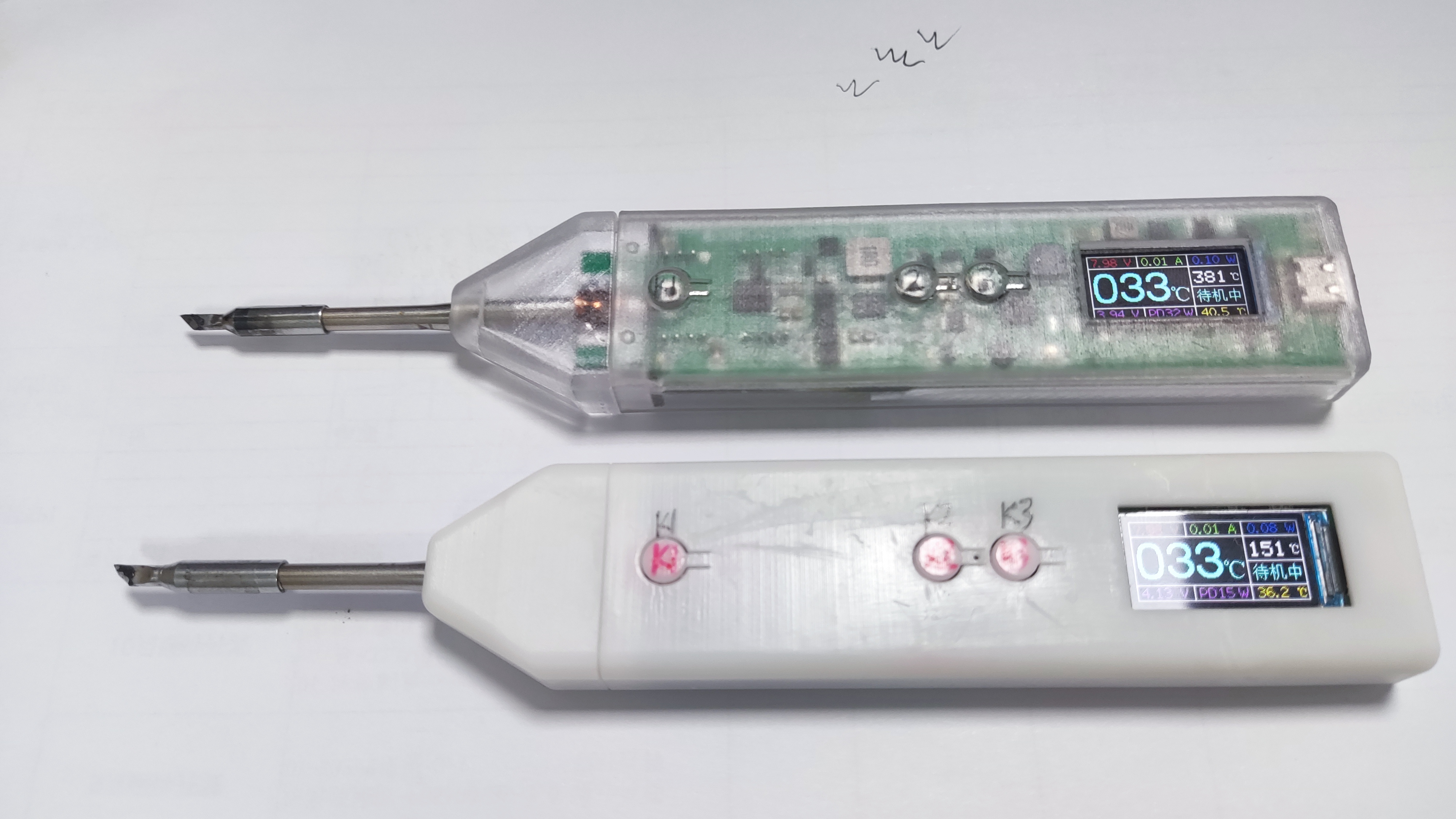
A portable, wireless soldering iron powered by a built-in lithium battery eliminates the limitations of wires, allowing for free soldering and making it the perfect choice for business trips and repairs.
Project Description:
The ESP32-C245 wireless soldering iron is a portable wireless soldering iron powered by a built-in lithium battery. It uses a C245 heating element and supports direct power supply via TYPE-C fast charging and lithium battery charging. It supports real-time measurement and display
of parameters such as soldering iron temperature, current, voltage, and power. Features:
1. Supports temperature range measurement and calibration from -100℃ to 450℃ .
2. Supports dual power supply via lithium battery and TYPE-C, automatically switching between power sources and charging the lithium battery.
3. TYPE-C input power: 5~20V/5A; PD fast charging trigger power default: 65W.
4. TYPE-C interface supports program download and fast charging trigger power supply (distinguished by reversible insertion).
5. Three commonly used buttons for mode switching and parameter settings; one reset button for program burning.
6. ST7735 0.96-inch 160*80 pixel color LCD screen displays various parameters
. 7. Supports multiple function settings and data retention even after power loss. 8. Low-power sleep mode (20uA) and button wake-up
. Maximum heating power is 20W when powered by lithium battery; heating speed is slightly slow; soldering above 350℃ is difficult; battery life is also relatively tight.
9. Maximum usable heating power is 99W when powered by TYPE-C; adjustable
current limit
. This project is licensed under the "CC BY-SA 4.0" license. Please do not use it for commercial purposes. When reprinting, please include the original source link and this statement.
Project Attributes
: 1. This project is being publicly released for the first time and has not won any awards in other competitions. It is an original open-source project by Negative Entropy Light (CC BY-SA 4.0).
2. Gitee repository link: https://gitee.com/arduino2021/ESP32-C245.git 3.
Project Progress
(November 22, 2023): 1. August 2023: Schematic and PCB design, prototyping, and verification of ESP32 Wireless Soldering Iron 1.0. 2.
September 2023: Schematic and PCB design, prototyping, and verification of ESP32 Wireless
Soldering Iron 1.1. 3. October 2023: Shell structure design of ESP32 Wireless Soldering Iron 1.1 and 3D prototyping at LCSC.
4. November 2023: Formal coding and testing begin, bug fixing and hardware/software and shell design improvements completed
. This project went through two iterations, costing over 600 yuan for PCB prototyping, 3D prototyping of the casing, and purchasing components.
Design Principles
: 1. The project uses an ESP32-S3FN8 as the main controller, which uses an ADC to collect the temperature and current signals from the soldering iron's thermocouple to control the PWM-driven PMOS switch, thereby controlling the soldering iron's temperature and heating power.
2. The HUSB238-002D chip is used for fast charging deception; however, this chip's support for fast charging protocols is not very good, and it cannot deceive some chargers into outputting the correct power.
3. The TPS61088RHLR is used to boost the battery voltage from approximately 3.7V to 8V to power the soldering iron and increase its heating power.
4. The XB7608AJ provides overvoltage, undervoltage, overcurrent, and short-circuit protection for the lithium battery. The SLM6305 is used for lithium battery charging
. 5. The LIS3DHTR is used for motion detection to determine whether the battery has entered deep sleep mode
. 6. The GS8552 amplifier is used to amplify the temperature and current signals from the soldering iron's thermocouple.
7. Due to the influence of the low-end current sampling circuit, the current during operation will affect the thermocouple temperature signal of the soldering iron. Therefore, intermittent sampling of the thermocouple temperature signal is adopted, and the temperature is obtained by looking up a table .
Function mode buttons :
1. Constant temperature heating mode: Short press K1 to switch between standby and working modes. Long press K1 to enter deep sleep mode. Short press K2 and K3 to set the target temperature.
Long press K2 and K3 to switch between different modes. 2. Function setting mode: Short press K1 to switch between different function settings. Long press K1 to enter and exit the more detailed parameter setting interface. Short press K2 and K3 to turn the function on or off and add or subtract parameters.
3. Calibration setting mode: Short press K1 to switch between different calibration parameters. Long press K1 to enter and exit the more detailed parameter setting interface. Short press K2 and K2 to add or subtract parameters and turn them on or off.
4. Deep sleep mode: In deep sleep mode, short press K1 to wake up and enter the constant temperature heating mode interface. In the constant temperature heating mode interface, long press K1 to enter deep sleep mode.
Constant temperature heating mode
1. Use short press K1 to switch between standby and working modes. 1. Short press K2 and K3 to set the target temperature; long press K2 and K3 to switch between different modes.
2. In standby mode, it only measures the soldering iron temperature without heating; it can be used as a thermometer.
3. During operation, it measures the soldering iron temperature and heats it to the set target temperature.
4. Target temperature range: -99℃~450℃.
5. Soldering iron temperature measurement range: -200℃~450℃. Range and accuracy are affected by temperature calibration parameters.
6. When no movement is detected, it starts a sleep timer to enter deep sleep mode. The timer resets upon detecting movement.
7. When the lithium battery voltage is detected to be below 3.2V, it will enter deep sleep mode.
Function Setting Mode
: 1. Short press K1 to switch between different function settings; long press K1 to enter and exit the more detailed parameter setting interface. Short press K2 and K3 to turn the function on (1) or off (0), or increase or decrease parameters
. 2. Maximum current setting: Sets the maximum heating current under different supply voltages to prevent excessive current from draining the power supply.
3. Working mode setting: Default standard heating mode. The intelligent heating mode automatically increases the temperature by 50°C upon detecting large solder joints. This feature is currently not fully optimized.
4. Motion Detection Settings: Set the acceleration detection threshold.
5. Sleep Time Settings: Set a sleep timer from 1 to 60 minutes; exceeding this time will enter deep sleep mode.
6. Screen Orientation Settings: Short press K2 or K3 to adjust the screen orientation.
7. Auxiliary Lighting Settings: Set the LED auxiliary lighting switch.
8. Buzzer Switch Settings: Set whether the buzzer sound is on or off.
9. Restore Default Settings: Setting parameter 1 restores all parameters to their default values and saves
the calibration settings. Mode
1: Short press K1 to switch between different calibration parameters. Long press K1 to enter and exit the more detailed parameter setting interface. Short press K2 to subtract, increase, or turn parameters on or off.
2. Measure the actual temperature of the soldering iron using an external, precise thermometer to adjust the set temperature value and maintain a constant temperature until the soldering iron reaches the desired calibration value. Then press the calibration switch to save the corresponding soldering iron thermocouple voltage.
3. When calibrating the voltage, the default calibration starts from 0℃. Place the soldering iron tip in an ice-water mixture for a while before calibration, then calibrate step by step. 500℃ may exceed the range.
4. Temperature calibration is best done with a professional thermometer. Multimeters are unreliable; calibration parameters below 0℃ cannot be calibrated and are theoretical calculations.
5. The default calibration parameters are not very accurate as they are obtained with a multimeter. Thermocouple voltages of soldering irons from different manufacturers are likely to differ; calibration is required before use.
6. To support temperature range measurements from -100℃ to 450℃, measurement accuracy from 0℃ to 450℃ has been sacrificed.
Software Instructions:
1. This program is developed based on the Arduino IDE. The source code, dependent libraries, and compiled burning files are included in the attachment. Beginners are advised to use the official ESP tool for burning.
2. Burning via the official ESP tool requires installing esp32 flash_download_tool_3.9.5 and loading the burning bin file. 3. Compile
and download the program via Arduino IDE. This requires installing the ESP32 development board and related libraries, and selecting the corresponding chip parameter configuration. Installation package version: esp32_package_2.0.14.
4. If there is no USB device when downloading the program for the first time, try a different plug. If the USB is not recognized, pull the P0 pin low (press the K3 key) and then press the reset button to enter forced download mode.
5. After successful forced download, press the reset button to restart the program. If the screen does not display anything, press the button to see if there is a response. If there is a response but the screen is still off, try waking it up from deep sleep mode.
6. If there is no response, no screen display, or a black screen after successful download, focus on checking the hardware soldering and download parameter configuration. If any abnormalities occur, try re-programming.
Hardware Assembly
: 1. The EESP32-C245 wireless soldering iron consists of: main control PCBA + adapter PCBA + lithium battery + casing + C245 soldering iron core.
2. The main control PCB and adapter PCB use ordinary RF-4 material, 2-layer board, 0.8mm thick. 1. The two boards are soldered together using pin headers. Note the orientation; do not solder them backwards.
2. The adapter board PCBA needs to be soldered with three types of beryllium bronze crown springs: O4.5-8mm / K10#-8 / K16#-6, one of each. See the picture for details. Note the ventilation; beryllium bronze soldering is toxic.
3. The casing uses SOLIDWORKS 2021 design. There are two similar designs: a large casing and a small casing. They are interchangeable, only slightly different in appearance. Choose one.
4. The recommended lithium battery is the Fuli 782768SV model aircraft battery cell, with a capacity of 1750mAh and dimensions of 68mm (L) x 27mm (W) x 7.2mm (H). See the picture for details. Other models can also be used as long as the parameters are suitable
. 5. The TFT uses the ST7735 0.96-inch 160*80 pixel color LCD screen with a solderable 13-pin interface. Note that only the ST7735 can be used; the ST7735S may not display
. 6. The C245 soldering iron tip uses the Sugong C245-SK small knife tip soldering iron tip.
Note
1. 1. This project is a CC BY-SA 4.0 open-source project. For large-scale commercial use, authorization from the original author is required.
2. This project heavily utilizes 0402 packaged components, making hand soldering difficult. Alternatively, using JLCPCB SMT is also an option, but the project is highly complex;
proceed with caution if you have the necessary skills. 3. When soldering model aircraft battery cells, it is recommended to discharge the voltage to 3.3V before soldering. Never reverse the positive and negative terminals, otherwise, it will release a magical smoke effect.
4. For 3D printed shells, choose high-precision materials for large shells and high-temperature resistant materials for small shells near the heat source.
5. Some parameters may be abnormal upon initial use; it is recommended to restore the default settings.
6. Abnormal software-controlled PWM drive constant current function can cause excessive current and power supply failure; use a high-power power supply to avoid this problem.
7. When soldering large pads at high temperatures, the maximum 20W heating power of the lithium battery may be insufficient; use a high-power power supply.
8. Component parameters are based on the schematic diagram. Components not available on the JLCPCB website can be found on Taobao. Related hardware and software materials are included in the attachments. The schematic diagram contains relevant notes.
9. This project is for personal DIY purposes only and has not undergone professional evaluation and testing. There may be hidden bugs. It is not yet perfect. Please be cautious when replicating and using it. You assume all risks.
Physical product shown.


Hardware documentation.zip
Structure data.zip
Operation demonstration.mp4
Software data.zip
PDF_ESP32-C245 Wireless Soldering Iron.zip
Altium_ESP32-C245 Wireless Soldering Iron.zip
PADS_ESP32-C245 Wireless Soldering Iron.zip
91031
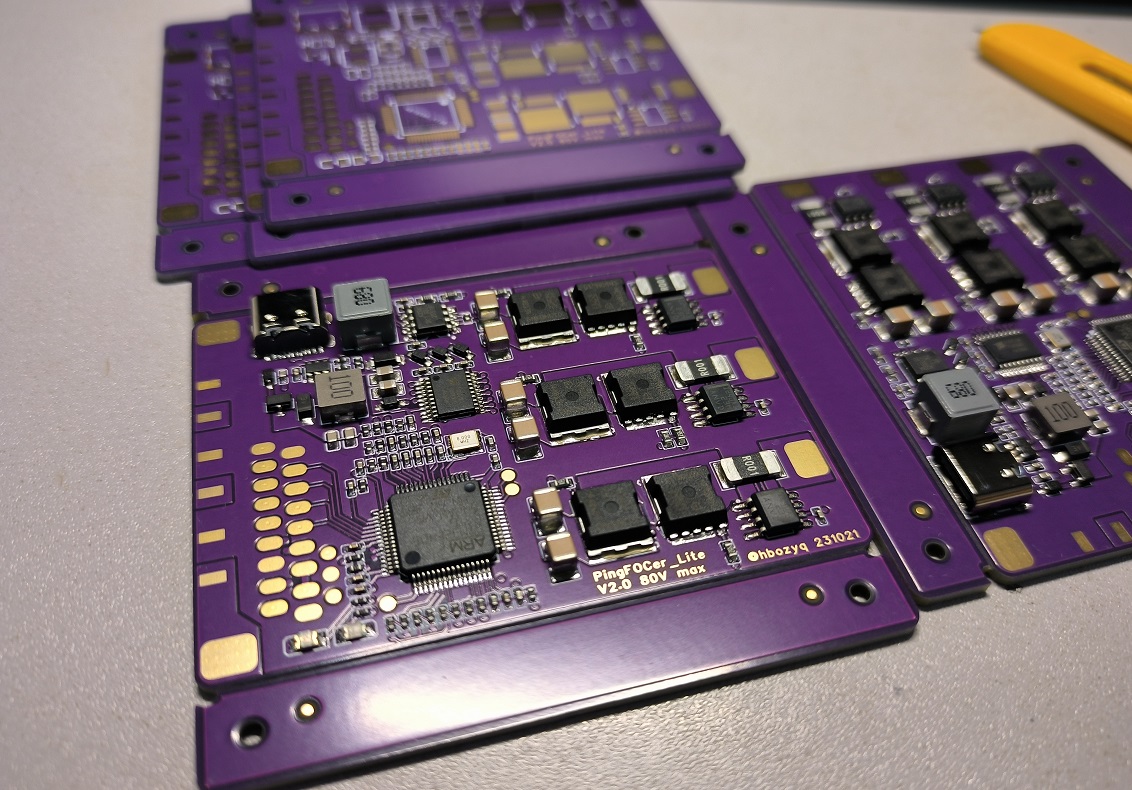
PingFOCerLite_V2.0
Higher power brushless motor controller compatible with VESC6.0
High-power brushless motor controller compatible with VESC® 6.0: Ping FOCer Lite V2.0
⚠WARNING⚠
This project has not been extensively tested. Hardware or firmware defects may still exist and affect use. Users assume all risks!
Improper use of high-voltage and high-power motors may result in personal injury or even death. The project author assumes no responsibility for this!
This project does not allow unauthorized commercial use for profit (especially selling data). For any commercial use, please contact the author. Small-batch sales at cost price are currently unrestricted.
Acknowledgements:
This software design is entirely thanks to the best open-source ESC on the planet: Benjamin Vedder's VESC® Project (https://github.com/vedderb/bldc). Please consider donating to him: https://vesc-project.com/donations
Due to copyright issues, the VESC® tool is not uploaded here. Please click the official download link: https://vesc-project.com/vesc_tool. Account registration and payment are required. All software prices are the same; different prices only represent different donations to the author. If you do not wish to donate, choose the free version.
(Note: VESC is a registered trademark of Benjamin Vedder. Only high-quality brands that meet his review criteria can use VESC as a certification. Most VESC and Keil source code sold on Taobao are illegal and infringing.)
The hardware is based on a modified schematic of Sharman's Cheap FOCer 2 (https://github.com/shamansystems/Cheap-FOCer-2). His excellent design sparked my interest in VESC and ultimately led to this design. Thanks to him for the detailed design and explanation.
JLCPCB sponsored free prototyping and SMT placement services for this project. Thank you for your support on this open-source journey.
Features:
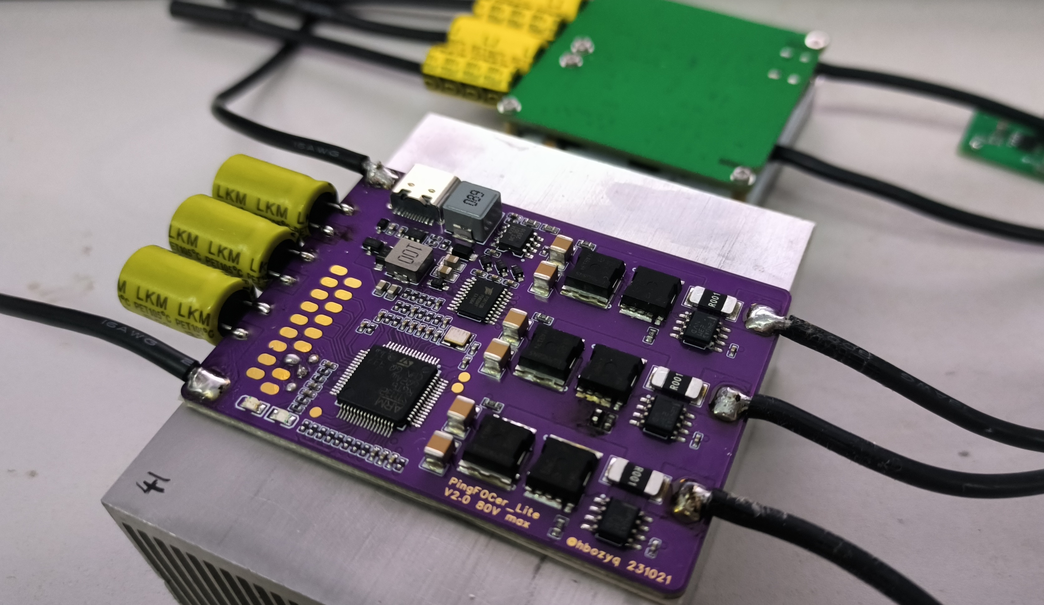
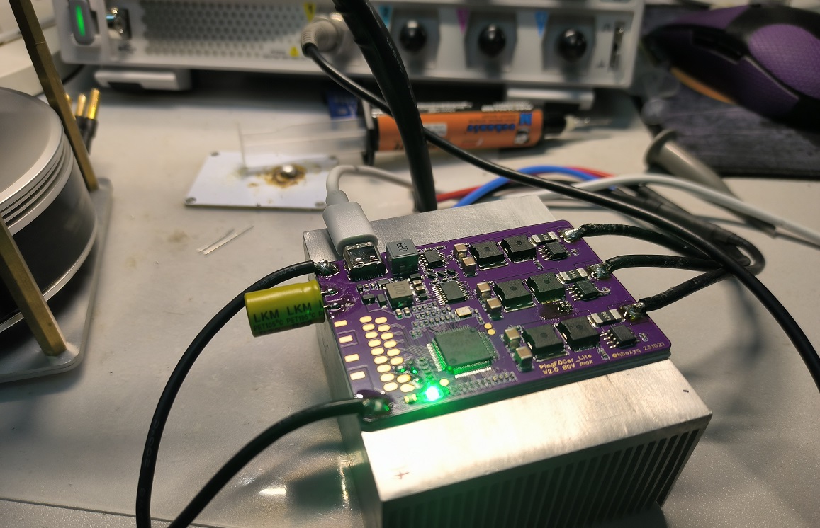
High power: Output power exceeds 1.5KW (actually measured)
Small size: Dimensions are 50*70*8mm (excluding wires and electrolytic capacitors)
Easy to order and install Use: PCB body can be sampled for free (6 layers), all SMD components are on the same side of the PCB, JLCSMT's economical surface mount service can be used (and is recommended)
Uses USB Type-C
three-phase current sampling, can use silent HFI function
I/O with ESD protection
USB does not draw power, requires connection to power to operate
Electrical specifications
Phase current: Continuous 60A (tested, requires external heatsink and forced cooling), instantaneous current >75A, sampling current range: ±82.5A
Maximum input voltage: 80V (absolute value, should not be exceeded at any time)
Recommended input voltage:
Disadvantages
Uses custom firmware that is not currently supported by the VESC project, requires self-compilation.
The hardware connector is inconsistent with the standard VESC, requiring soldering.
It lacks CAN functionality (too much space).
[Image of the actual product ]

Other considerations:
The current amplifier is compatible with INA240 and AD8418. Note the package and amplification factor.
The MOS used is the IST019N08NM5AUMA1 (80V 1.9mR) available from LCSC. Alternatively, salvaged parts such as IAUA250N08 (80V 1.8mR) can be selected; this package should not currently have counterfeit products.
The BOM does not include a large bus filter capacitor (10mm diameter), requiring the use of high-frequency, low-resistance electrolytic capacitors; solid-state capacitors are recommended.
The verification board uses 6-layer 2OZ thick copper, which is relatively expensive. Free samples of 1OZ/0.5OZ have slightly lower thermal performance but are cheaper; the choice is yours. (Group buying could be considered to lower the price.)
PingFOCer_Lite_V2.0.bin
PDF_PingFOCerLite_V2.0.zip
Altium_PingFOCerLite_V2.0.zip
PADS_PingFOCerLite_V2.0.zip
BOM_PingFOCerLite_V2.0.xlsx
91033
2KW high-power uninterruptible power supply
A 2kW high-power inverter with 48-72V input, supporting uninterrupted power supply and charging functions.
Project Description:
This project was designed by Lei Chaolin of the New Energy Application Laboratory at Hunan University of Science and Technology. This project is provided for learning and exchange purposes only. Replication is welcome, but commercial use is strictly prohibited.
Welcome to join the QQ group 458720579 for discussion. Your likes and favorites are my motivation for the next project!
For any questions, please join the QQ group for consultation!
Open Source License

Project Functionality
Input: DC48V-72V;
Maximum Output Power: 2000W;
Output:
AC220V sine wave x2;
USBDC x2 (maximum 100W);
Power, Capacity, and Output Voltage Display;
Each AC output port has an independent switch for shutdown control;
Protection Circuit:
Short circuit protection;
Overload protection;
Temperature protection;
Battery overcharge protection;
Surge protection; Reverse connection protection
;
Voltage regulation protection;
Project cost is approximately 500 RMB.
Project Attributes:
This project is being publicly disclosed for the first time and is my original work. This project has not won any awards in other competitions.
Project Schedule:
July 2023: Project started;
August 2023: Main circuit designed;
September 2023: PCB completed;
October 2023: Successful debugging.
Design Principles:
First, we analyzed the project requirements and found that it was a wide-range input inverter, with voltage from 48V to 72V, and it also needed to support battery power. When mains power is available, it supplies power through the mains; when the mains power fails, the inverter needs to operate immediately.
Normally, when mains power is available, it needs to charge the battery. This is essentially a UPS (Uninterruptible Power Supply). Most commercially available UPSs use a single-range input and employ DAB (Dynamic Amplifier) active resonant current for bidirectional current flow, allowing the battery to both supply power and charge.
However, according to the chip datasheet, when charging the battery, the PFC boost voltage is a maximum of 450V, and after resonant (4:30) through the transformer LLC to the battery, it reaches 69V. We know that a 72V battery needs to reach 80V to fully charge, so the EG8026 chip is not suitable for our needs.


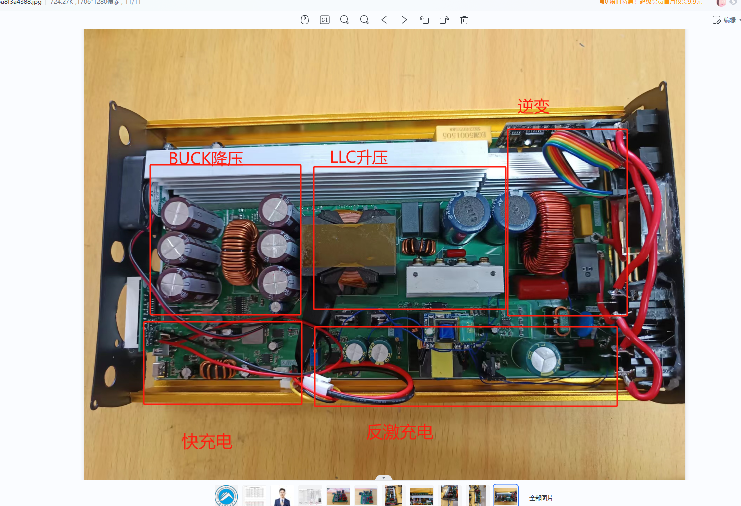
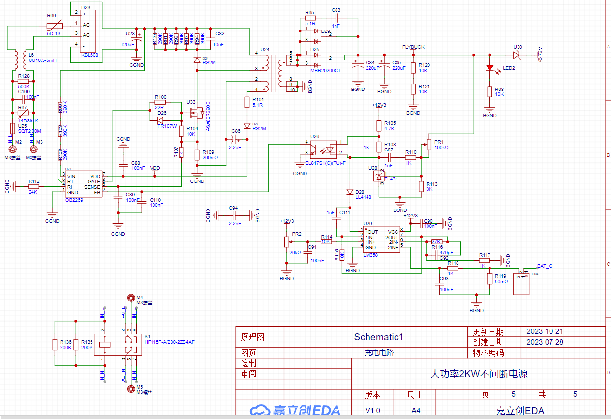
At this point, a charging circuit is needed to charge the battery separately. Therefore, my topology is BUCK+LLC+SPWM+FLYBUCK.
Below is my topology diagram.

Batteries ranging from 48V to 72V are uniformly stepped down to 48V via a synchronous BUCK circuit, and then boosted to the 350V DC bus VBUS voltage via LLC resonant soft-switching technology, and then inverted via SPWM.
This perfectly solves the problem of wide-range input voltage, supporting a maximum input voltage of 100V.
The charging section uses a FLYBUCK circuit for constant current charging with a power of 200W and an output voltage of 48V-80V.
The following is a detailed explanation of the circuit used:
1.1 Primary EG1163S Synchronous Buck Circuit

The four input MOSFETs are reverse connection protection circuits. After that, there are three 1000uF/100V black diamond capacitors connected in parallel. Then, the synchronous BUCK circuit is used to step down the voltage through the upper and lower transistors of the two MOSFETs connected in parallel, with a current-limiting resistor in the middle for overcurrent protection. Due to a synchronization issue discovered during EG1163S debugging, an additional Schottky high-current diode (U4) was added to distribute some of the current. The BUCK output also uses three 1000uf/100V high-capacity capacitors. The chip's external circuitry is simple yet powerful. If instability occurs, adjust the loop compensation feedforward capacitor, adding an appropriate amount, such as 100nF, and then check if the subsequent output is normal.

1.2 LLC Resonant Circuit
The LLC resonant boost section uses the EG1611 chip. This chip can output a fixed-frequency PWM signal, and the frequency can be adjusted via resistor R43. The frequency needs to match the resonant cavity frequency of the LLC stage to achieve soft-switching technology, greatly improving efficiency.
The subsequent stage uses open-loop voltage control. When the output voltage exceeds 450V, feedback protection is implemented. The EG2132 is the gate driver. The transformer was purchased from Taobao; the 48V 2KW transformer with a leakage inductance of 18uH can be found in Yijing Micro's Taobao shop. A 650V 10A diode can be used as the rectifier diode. R24 and R26 are discharge resistors, used to discharge any residual charge in the capacitors.

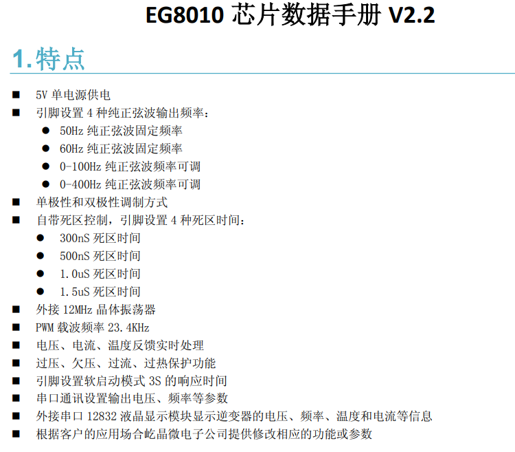
1.3 Inverter Circuit
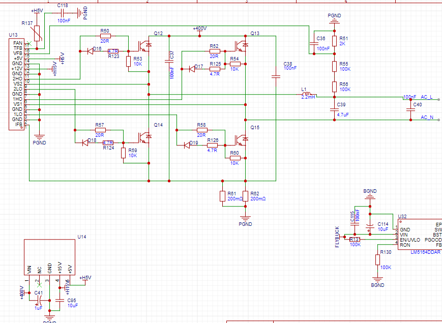
The inverter circuit consists of an EG8010 small board and four IGBTs. MOSFETs can also be used, but they need to be at least 20A current rating and are packaged in TO-247.
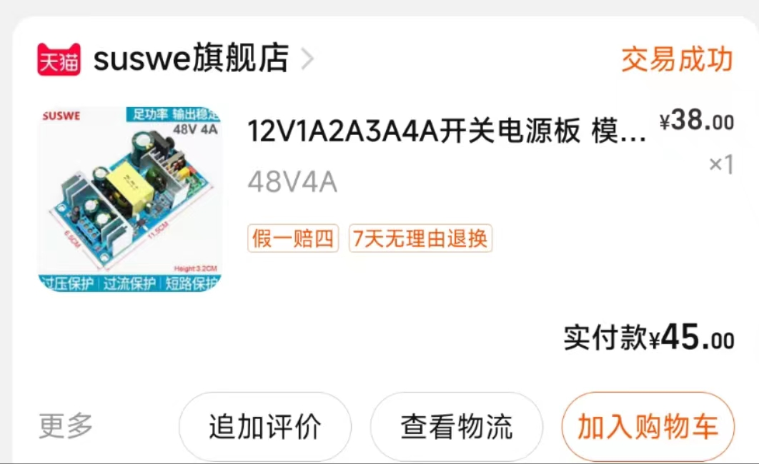
U14 is the auxiliary power module, available on Taobao.
1.4 Auxiliary Power Supply Circuit
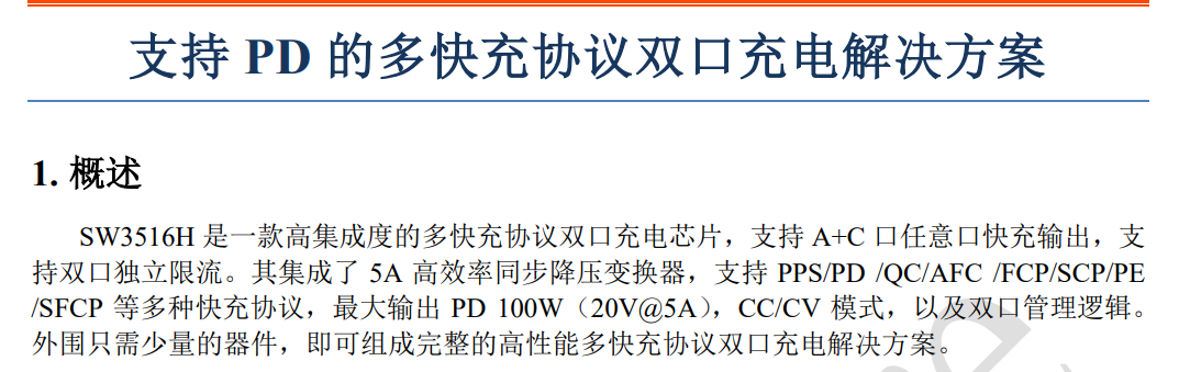
The auxiliary power supply consists of three Texas Instruments high-voltage input BUCK chips, an EG1163S step-down chip, and an SW3516H fast charging circuit. The SW3516H chip reduces the 23V voltage to the 5-20V fast charging voltage for mobile phones, supporting 100W fast charging.
The EG1163S is a synchronous step-down chip, and the MOSFETs are 100V 20A external MOSFETs in a DFN5x8 package .
The Texas Instruments LM5164 has very high performance, supporting up to 100V input, and so far, none have burned out, demonstrating its high reliability.

1.5 Charging Circuit
The charging circuit features AC input surge protection and capacitor current limiting protection. The main power management chip is an OB2269 flyback chip, and the power switching transistor is an 800V 10A or higher NMOS. The transformer was purchased from Taobao (you can buy it there). The output uses constant voltage protection and constant current charging.
An LM358 amplifies the current signal and then provides current feedback. During charging, the voltage decreases while the current remains constant. When the battery is fully charged, the current begins to decrease while the voltage remains constant. The relay is used for continuous switching.
Debugging Steps:
We should solder the flyback component first, as it is more difficult to adjust and is also the most dangerous. After soldering, adjust the voltage potentiometer to 48V, then connect a load, preferably a 40-ohm load. Rotate the current potentiometer clockwise, observing the ammeter to ensure a constant current. Then, switch to a 20-ohm load to check for a constant current effect. Finally, adjust the current to 2A.

For the LLC (Limited Cable) section, we can connect a current transformer in series with the rectifier bridge's preamplifier stage, apply a 200W load, adjust the frequency to 56kHz, and then observe whether the waveform is sinusoidal. If it is sinusoidal, then the LLC is in a resonant state. If the waveform becomes elliptical, it indicates inductive operation, meaning the frequency is too high.

Main Components BOM (Bill of Materials)
Model
Quantity
Purchase Channel
IRFP4568PBF
8
LCSC Mall
EG1163S
2
LCSC Mall
SGT50T65FD1PN
4
LCSC Mall
LM5164DDAR
3
(LCSC Mall)
, 47UH 30A inductor
(
Taobao),
modulation inductor
(
Taobao),
flyback transformer
(
Taobao),
EG8010 small board
(
Taobao) ,
SW3516H
(
Taobao) ,
LLC transformer
(
Taobao),
EG1611
(
Taobao ),
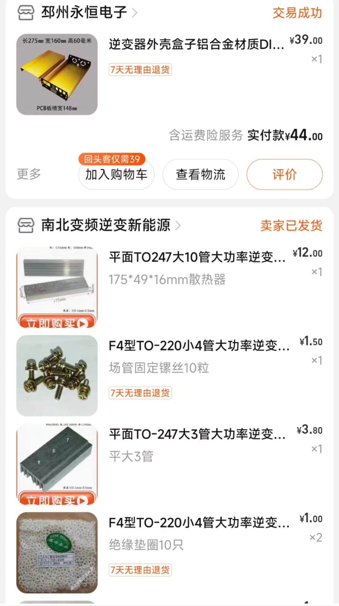
casing
(
Taobao) .


Physical display
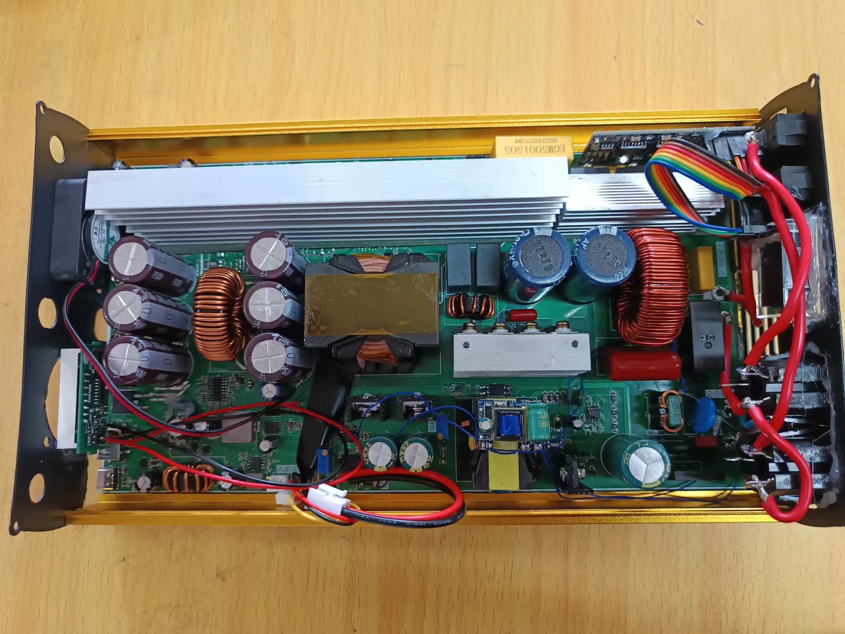
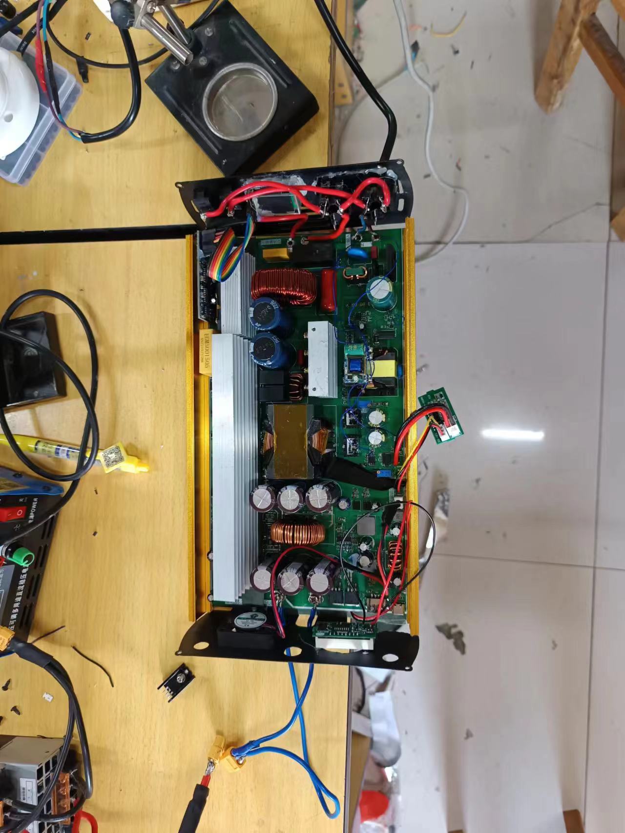
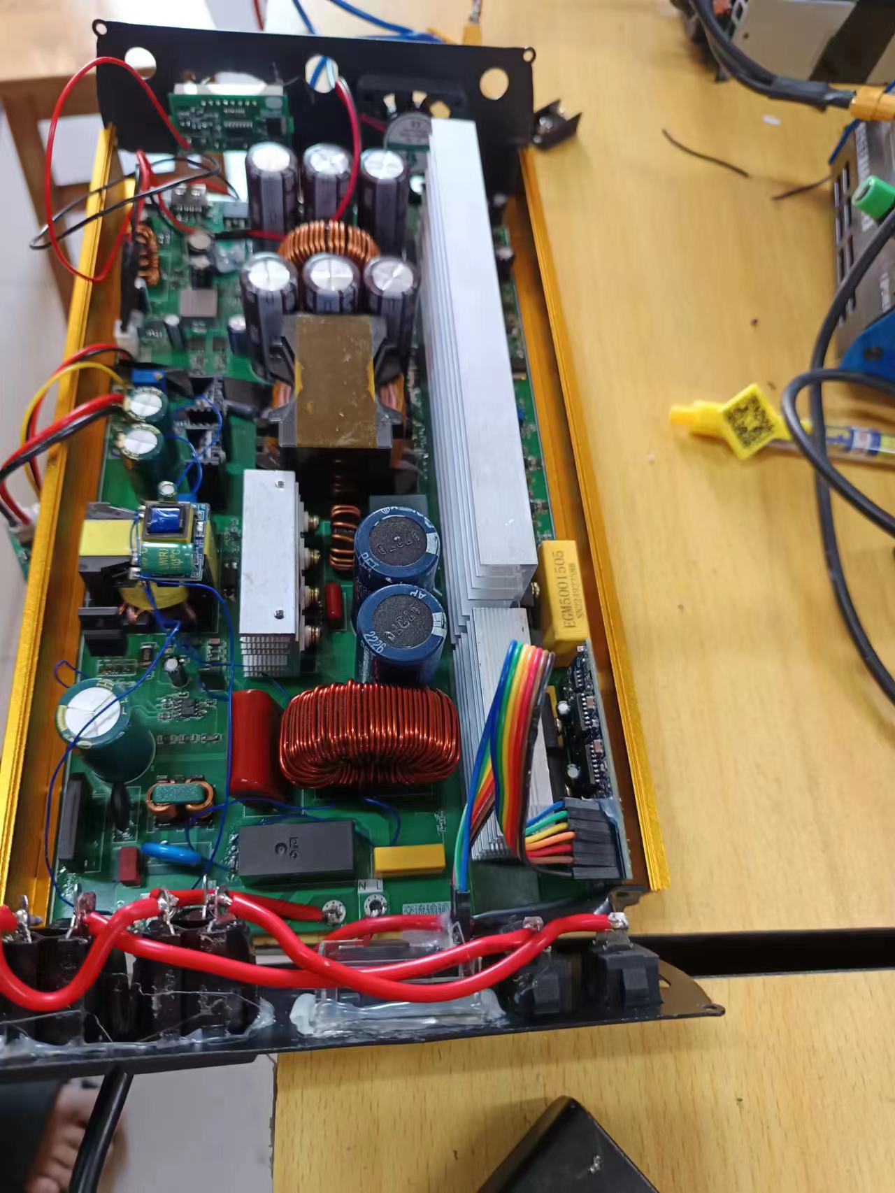

and design notes:
Remember to take proper insulation measures during installation, especially for the 220V output, as it can be harmful to the human body. Currently, the most difficult parts to debug are adjusting the frequency and setting the charging voltage and current.
Other parts are functional upon power-on. When connecting voltmeters and ammeters, pay attention to the positive and negative terminals; do not reverse them, as this can damage the meters.
Current testing shows stable operation. For heat dissipation, consider adding a cooling fan.
Other
Bilibili test videos
: https://www.bilibili.com/video/BV1Mh4y1i7vF/
EGS002_manual_V1_1.pdf
EG8010 Datasheet.pdf
EG1163S.pdf
EG1611 Chip Datasheet V1.0(20180416m).pdf
Uninterruptible power supply demonstration.mp4
PDF_High-power 2KW Uninterruptible Power Supply.zip
Altium 2KW High-Power Uninterruptible Power Supply.zip
PADS_High Power 2KW Uninterruptible Power Supply.zip
BOM_High-power 2KW Uninterruptible Power Supply.xlsx
91035
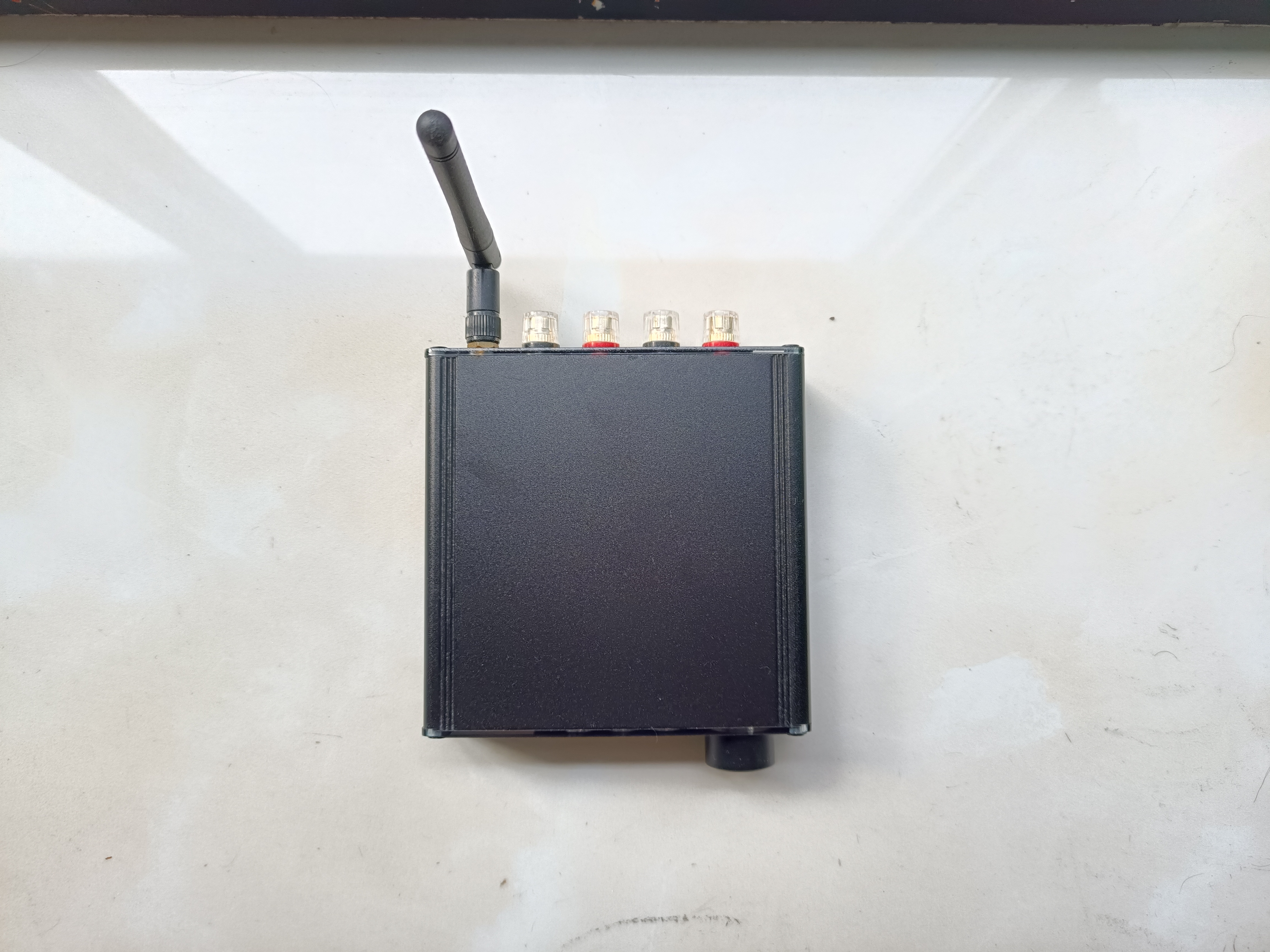
Mini USB Bluetooth Digital Amplifier
The mini USB Bluetooth digital amplifier uses the XMOS XU208 digital interface and QCC5125 Bluetooth receiver module to receive USB and Bluetooth audio. The amplifier chip uses Infineon MA2304DNS digital amplifier, which can realize direct power amplification output of digital audio signals.
Features:
Flexible Audio Input:
- Type-C interface, supports USB 2.0 high-speed audio input, supports sampling rates of 32kHz, 44.1kHz, 48kHz, 88.2kHz, 96kHz and 192kHz and bit widths of 16bit, 24bit, and 32bit
- Bluetooth mode, supports LDAC, AptX and other inputs, supporting a maximum sampling rate of 96kHz and a bit width of 24bit
Multi-Level Class D Amplifier:
- Low power requirements, no heat generation
- Efficiency >50% at 1W output power
High Output Power:
- Supports 2x37W dual-channel output (THD=10%), minimum load of 4Ω, meeting the needs of desktop speakers
- THD+N: 0.05%, 5W, 1kHz
Excellent Housing and Panel Interface Design:
- Housing size approximately 10.5cm × 10cm × 3cm
- Power supply DC-005 interface input, 12~18V
- 4mm crystal binding posts for quick cable plugging and unplugging
- USB Type-C The audio input interface abandons the bulky Type-B, offering a more modern look and allowing easy connection to phones and computers. The
SMA RF interface allows for the removal of the Bluetooth antenna.
User-friendly interaction features include:
a rotary encoder for volume adjustment, digital volume control for easy volume control, and
button control for Bluetooth playback and volume, enabling easy song switching without looking at the phone
. A display shows the sampling rate, current operating status, volume level, etc. (I'm too lazy to do more).
Description:
The MA2304DNS is a 2x37W audio amplifier with an integrated audio DSP and I2S/TDM audio interface. This audio amplifier utilizes MERUS™ multilevel switching amplifier technology, achieving unparalleled power efficiency at both low and high output power. Multilevel switching also reduces EMI and enables inductorless applications at a lower cost without compromising audio performance or efficiency. A high-order internal feedback loop ensures low THD for excellent audio performance. The integrated DSP provides configurable processing flow for correcting and tuning practical speaker applications such as equalization, limiting, etc. With the XMOS digital interface and QCC5125 Bluetooth module, high-definition USB and Bluetooth LDAC audio input can be achieved, thus meeting desktop HiFi needs.
System Architecture:

This power amplifier consists of five parts: 1. MA2304DNS digital audio power amplifier; 2. STM32F051 main control circuit; 3. QCC5125 Bluetooth audio circuit; 4. XMOS digital interface circuit; 5. Buck power supply circuit. The circuit uses JLCPCB four-layer board technology and measures 10cm × 10cm.
The XU208 and QCC5125 are responsible for receiving and converting USB and Bluetooth audio respectively. The two I2S signals are selected by SN74LVC244 and sent to the MA2304DNS power amplifier for audio decoding and amplification.
The output clock of the XU208 is re-aligned through a D flip-flop to eliminate clock jitter caused by the XMOS itself.
The QCC5125 module is connected to the antenna using an IPEX interface, improving signal quality.
To reduce power-on surge, a PMOS transistor was used for slow power-on processing at the power input (this feature has been abandoned).
The STM32F051 main controller is responsible for decoding the selected decoder and controlling the amplifier output volume via I2C. The rotary encoder also functions as a button; a long press switches the audio source.
An LCD/OLED display shows amplifier status information (I was too lazy to implement this).
Conclusion:
This mini USB Bluetooth digital amplifier is an improvement on its predecessor, enhancing interactivity and connectivity. It also features a casing and panel, enabling direct power amplification and output of digital audio signals, making it an essential HiFi product for home use.
Finished product showcase:


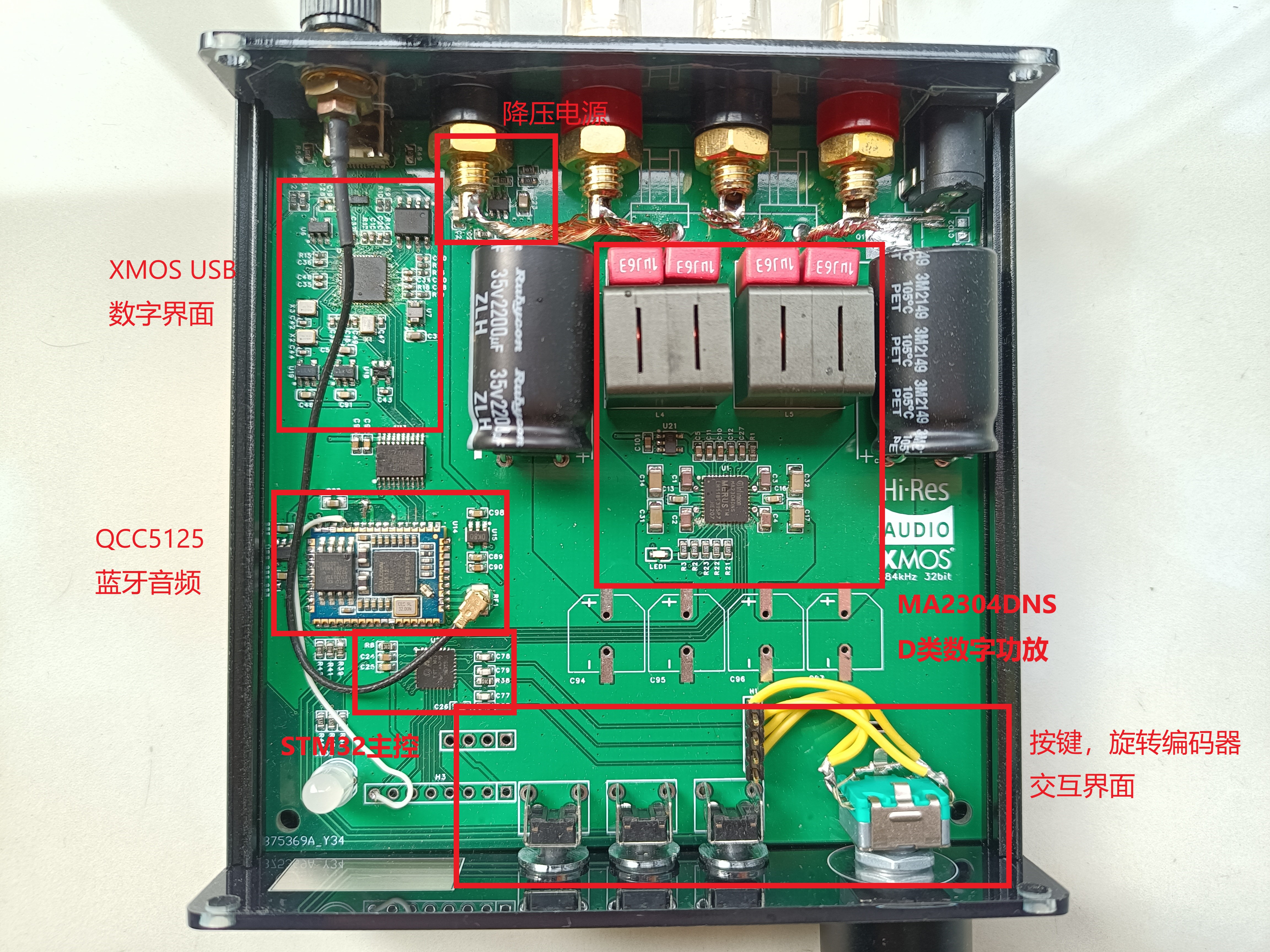
Internal photos, all details are included.
haruhikage.mp4
PDF_Mini USB Bluetooth Digital Amplifier.zip
Altium Mini USB Bluetooth Digital Amplifier.zip
PADS_Mini USB Bluetooth Digital Amplifier.zip
BOM_Mini USB Bluetooth Digital Amplifier.xlsx
91036
[Fully Open Source] Old Tyrant Game Console Ornament, based on ESP32-S3 development board, supports external gamepad and keyboard operation.
This is a game console accessory based on the ESP32-S3, capable of playing NES games and supporting ROMs up to 1MB in size.
Games support onboard gamepads, WeChat mini-program gamepads, HID gamepads, and HID keyboards [two-player mode supported].
This is a game console accessory
based on the ESP32-S3, capable of playing NES games and supporting ROMs up to 1MB in size.
Games support onboard controllers, WeChat mini-program controllers, HID controllers, and HID keyboards (two-player mode supported).
XBOX and PS4 controllers require additional modules for support. Already compatible.
Additional features: MJPEG video playback/computer status monitoring, etc.

Author:
Up: Twilight of Sanaran
Up: Mysterious Treasure Room
Video Overview :
https://www.bilibili.com/video/BV1eh4y1F7rn
Video Function Usage Demonstration:
https://www.bilibili.com/video/BV16F411o7L7
QQ Group
Number: 739444215, details and materials shared in the group. Source Code
Download
: The overall code uses the Arduino framework, developed based on the VSCODE+PlatFormIO platform. This code has also been adapted. Project: Eye of God [Up: Twilight of Sanaran], Project: 50mm Beam Spectroscope Large TV [Up: Mysterious Treasure Room]
Open Source Code Address: https://github.com/planevina/esp32s3_nes_gamer
After two months of tinkering, I tried all the NES emulators on GitHub. They were either too slow, had too many bugs, or were IDF versions. I encountered countless pitfalls, all tears.
The final main emulator code framework was reorganized and repaired using the GitHub NESCat project, ported to the S3, and many processes were moved to PSRAM, resulting in loading and running speeds that are more than ten times faster. After all, we're using the N16R8 module, which has 8MB of PSRAM. Furthermore, the number of ROMs that can be emulated has been increased to 1MB. Currently, except for some very large ROMs and some heavily modified ROMs that cannot run, most ROM games can be emulated smoothly.
Functionality Overview
: 1. As an NES game emulator, after parsing the game, it displays the game on a 3.2-inch color screen, outputs sound signals via I2S, and uses a super powerful speaker; the sound combined with the vibration feels fantastic! 1. **Mute Functionality:
** Can be set to automatically launch an application or a specific game upon startup. [As a decorative piece, it runs a game demo upon startup, which is quite cool.]
2. **Secondary Functionality:** MJPEG player for playing MJPEG video files. [Applications can be set to automatically launch upon startup.]
3. **Secondary Functionality:** Secondary computer monitoring screen, used with AIDA64 to display real-time CPU/memory usage status. [Applications can be set to automatically launch upon startup.]
Hardware:
1. The Old Tyrant core board
can be used not only for this game console project but also as a comprehensive ESP32-S3 development board. It features 2.54mm pitch header pin headers for I/O and power expansion, allowing for future expansion to accommodate any desired functions.
The core board features:
UART interface: for programming and debugging;
USB Type-C interface: for programming and designing USB applications;
TF/SD card interface: MMC mode, supporting up to 32GB capacity;
Standard USB A female connector: for expanding HID controllers, HID keyboards, etc.;
Lithium battery charging/discharging circuit: can be disconnected from the USB cable;
DC-DC power supply: provides sufficient power to modules and accessories, and reduces power consumption and heat;
I2S audio amplifier circuit: excellent sound quality;
IPS display interface: also includes a reserved touchscreen circuit, allowing it to function purely as a touchscreen development board for ESP32-S3, and is also good for LVGL development. The touchscreen can be directly attached to the back of the old-style core board for perfect compatibility.

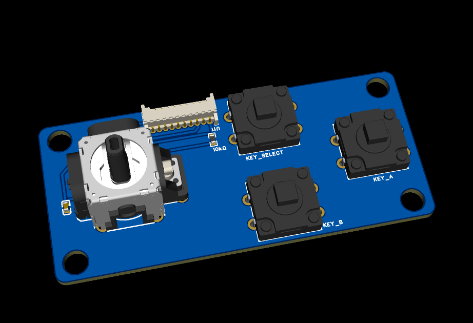
2. Joystick expansion board
for expanding the front joysticks and buttons of game consoles.
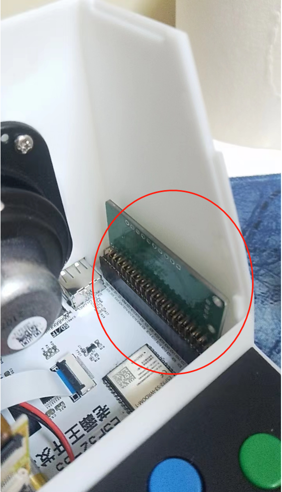
3. USB expansion module:
this board is not needed if you don't use XBOX or PS4 controllers.
This module is a patch because the 2-bit up's capabilities are limited, and they are not familiar with HID development. Currently, there is not much reference code for S3 to directly drive XBOX and PS4 controllers, so hardware is used to compensate.
I hope that one day other experts will fill in this gap and fully debug the USB library that comes with the S3.
For those who want to expand their PS4 or Xbox controller usage, this expansion board is needed. It plugs into the dual-row expansion pins of the core board, and resistors R27 and R28 are removed to expand the USB-A female connector, allowing for compatibility with more USB HID devices. The
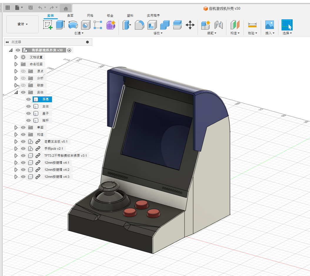
casing
is designed separately; you can see how detailed it is when you print it yourself. The QQ group also provides more building materials, including BOM recommendations, component links, etc., and you can also build it with other like-minded friends. Keep going, build your own game console and give yourself a proper ending to your childhood!
PDF_【Fully Open Source】Old Tyrant Game Console Ornament, Based on ESP32-S3 Development Board, Supports External Gamepad and Keyboard Operation.zip
Altium_【Fully Open Source】Old Tyrant Game Console Ornament, based on ESP32-S3 development board, supports external gamepad and keyboard operation.zip
PADS_【Fully Open Source】Old Tyrant Game Console Ornament, based on ESP32-S3 development board, supports external gamepad and keyboard operation.zip
BOM_【Fully Open Source】Old Tyrant Game Console Ornament, based on ESP32-S3 development board, supports external gamepad and keyboard operation.xlsx
91037
Switching power supply programmable feedback
Design based on STC8G for active serial port control power feedback signal management
Project Description: This project describes
a digital control switching power supply feedback system based on the STC8G microcontroller, licensed under
CC
-BY-NC-SA-4.0.
The system
controls the output voltage of the switching power supply via serial port data transmission and reception, and transmits real-time voltage and current data back to the host computer via serial port. Data can be directly connected to a computer for power supply output control, or connected to other microcontroller devices as a host computer.
Project Attributes:
This is the first public release of this project, and it is the author's original work. This project has not won any awards in other competitions.
Design Principles:
The circuit framework of this verification board

is divided into a main power supply section,
a digital feedback section, isolated power supply, and

a host computer communication section with safety isolation.

Working Principle:
The output voltage and current values are sampled in real-time by the MCU's built-in ADC channel. The voltage and current values control the MCU to output a PWM signal with varying duty cycle, which is then fed back to the primary side of the main power supply. (Optical isolation)
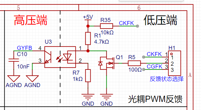
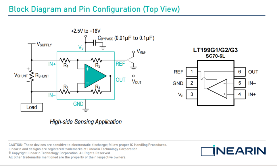
Current sampling uses the LT199G1, modified from the original official circuit to low-side detection, making it suitable for current detection at higher voltages. The voltage signal across the sampling resistor is amplified by the LT199G1 and then input to the STC8G-ADC pin. The output of the LT199G1 is clamped by a Zener diode to prevent the output voltage signal from being too high and damaging the MCU.

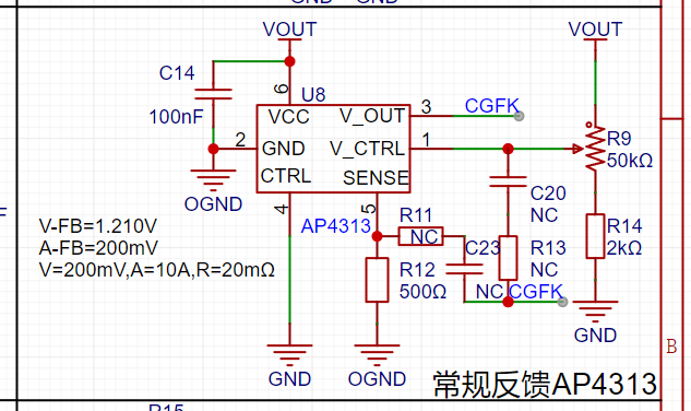
By switching the feedback type, it can also be used as a regular adjustable output voltage switching power supply.
After switching the jumper cap to regular feedback, the output voltage can be adjusted via potentiometer R9 on the board
(reserved for ordinary feedback - AP4313).
Software instructions:
The microcontroller program is based on the STC8G microcontroller (see attached program project).
Serial port transmit and receive data format
: Note: When downloading the program, the MCU clock frequency is set to 27MHz via the programmer.

The host computer uses LabVIEW 2018 to write
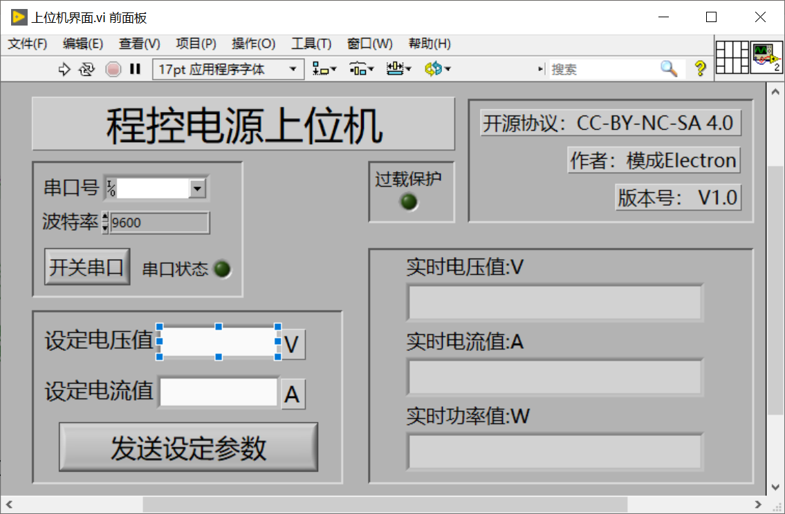
the communication baud rate, which needs to be changed to 115200bit before startup.
Physical demonstration:
PCB power-on test.


Design considerations:
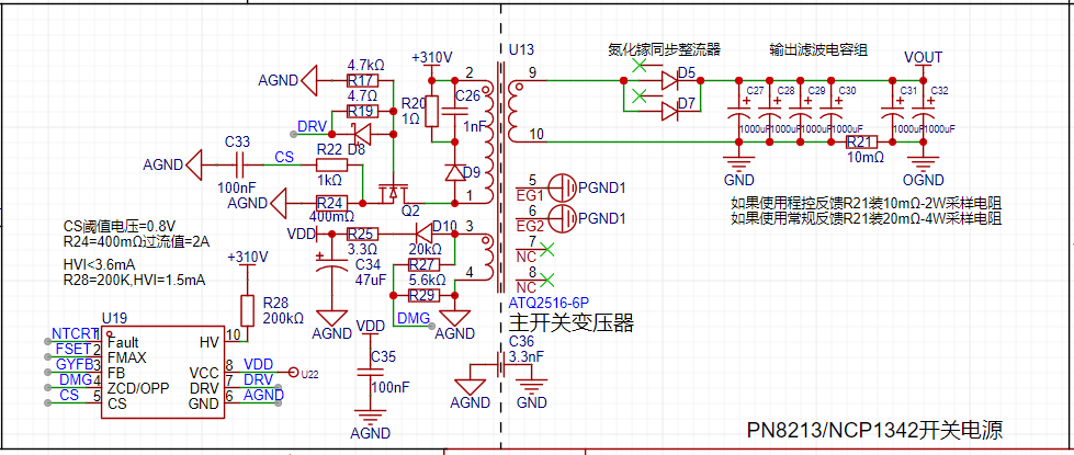
Currently, all key parts of the overall PCB have been successfully tested, but there are still problems with the main power supply section (I hope an expert in switching power supply design can help me look at the problem; I am only a beginner in power supply design and do not recommend using this part of the circuit for now). After powering on, the NCP1342 has a control signal output, but the output frequency is always only 25KHz. Adjusting the frequency setting resistor has no change in the switching frequency. According to the datasheet, it may be running in low power mode (light load mode), but I don't know how to get out of this mode. There is relatively little public information about the NCP1342 online. The domestically produced alternative, PN8213, is still unavailable.
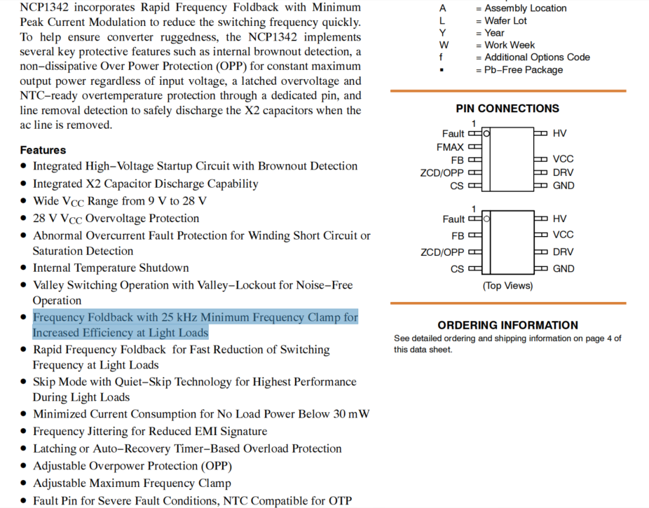
Soldering the power transistor will cause both the power transistor and NCP1342 to break down. During the overall testing, it operated stably once, but after restarting, both the power transistor and NCP1342 exploded.
Transformer parameters: Primary: 0.5mm enameled wire 40T+40T, Feedback: 0.5mm enameled wire 4T, Primary: 1mm*4 enameled wire 4T (4 parallel). Transformer core is ATQ2516.
Other
accessories include a video demonstration of the programmable feedback section (feedback control boost DC-DC-fb pin), output acquisition of real-time voltage and current values, and physical power-on status detection testing.
Programmable Power Supply Project.zip
1074_0bc3ueqmbkyg6aagrwimczstjiieyc5anuca.f0.mp4
eaffae.mp4
af233.mp4
PDF_Switching Power Supply Programmable Feedback.zip
Altium_Switching Power Supply Programmable Feedback.zip
PADS_Switching Power Supply Programmable Feedback.zip
BOM_Switching Power Supply Programmable Feedback.xlsx
91038
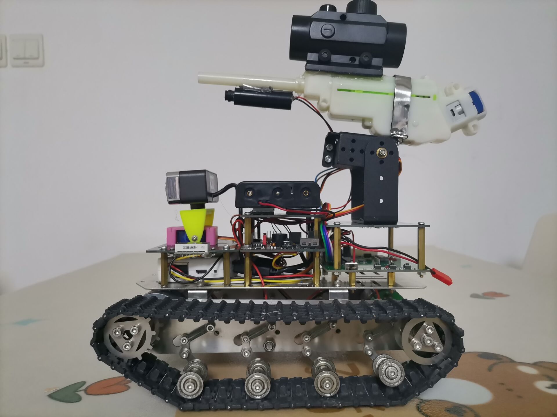
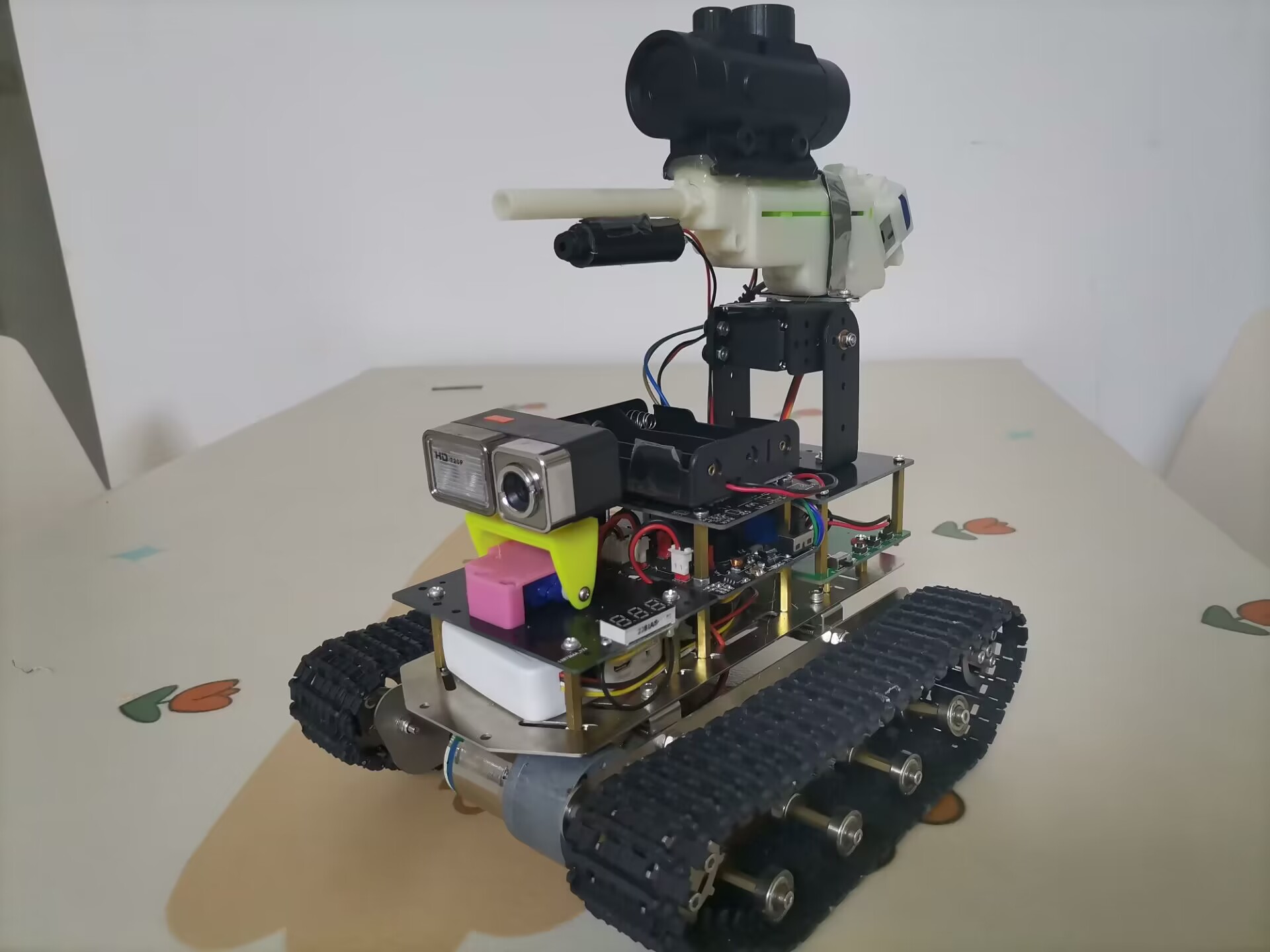
Multi-functional tracked vehicle
It adopts a metal tracked vehicle chassis, uses a high-definition camera and a Wi-Fi router, and connects to a mobile phone wirelessly. Users can receive video and control the tracked vehicle through their mobile phones. It can also be equipped with water gun components or mechanical grapples.
Project Description:
The tracked vehicle chassis, wireless router, HD camera, and water gun assembly in this project are off-the-shelf components. Other components, including the main control board, rotating gimbal expansion board, and rotating gimbal itself, are all custom-designed.
Project Functions
: 1. Tracked chassis with two geared motors for power, offering good overall load-bearing capacity, climbing ability, and passability.
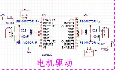
2. Uses an L293D motor drive, allowing for PWM control of motor forward/reverse rotation and speed adjustment.
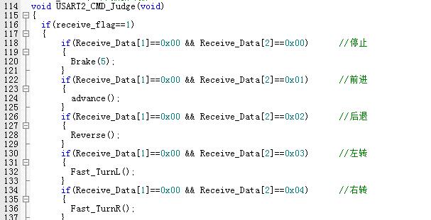
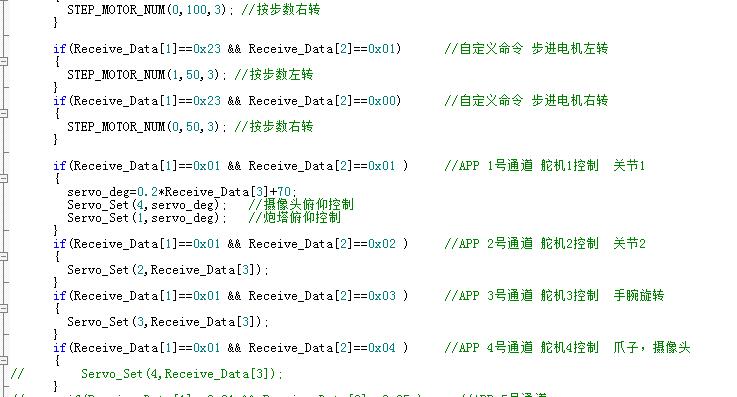
3. Can be controlled via a mobile app for forward, backward, left, and right turns of the tracked vehicle. It can also control the servo motor, water gun firing, chassis lights, and infrared laser activation/deactivation. The app displays real-time footage from the tracked vehicle's camera.
4. The tracked vehicle's camera is connected to the chassis via a servo motor for pitch control.
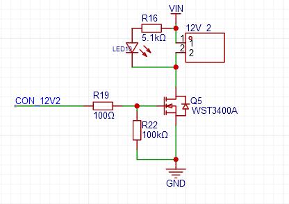
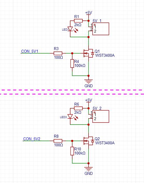
5. The main control board has two power supplies controlled by MOSFETs: one 5V and one 12V (input voltage). In this project, 5V powers the infrared laser head, and 12V powers the LED strip, which can be controlled to turn on or off via a mobile app.
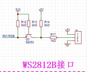
6. It includes a 3.3V to 5V level conversion circuit to drive the WS2812B LED strip.
7. An NRF2401 module interface is reserved for future remote control of the tracked vehicle. 8.
An ultrasonic interface is reserved for future installation of an ultrasonic module.
9. Four servo motor interfaces are reserved; only two are used in this project: one controls the camera's pitch, and the other controls the water gun's pitch.
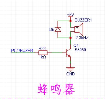
10. The main control board includes a buzzer circuit for alarm sounds and low voltage alarms.
11. A water gun assembly is installed on the vehicle body, capable of firing water bullets. Pitch is controlled by an MG996 servo motor, and azimuth follows the vehicle's rotation. The water gun is powered by a separate 2S lithium battery and controlled by a MOS switch; a double-tap on the mobile app screen fires one water bullet.
12. An infrared laser head is installed under the barrel of the water gun. The laser head module and the 3.3V voltage regulator module are encapsulated in a cylindrical tube, requiring only 5V power.
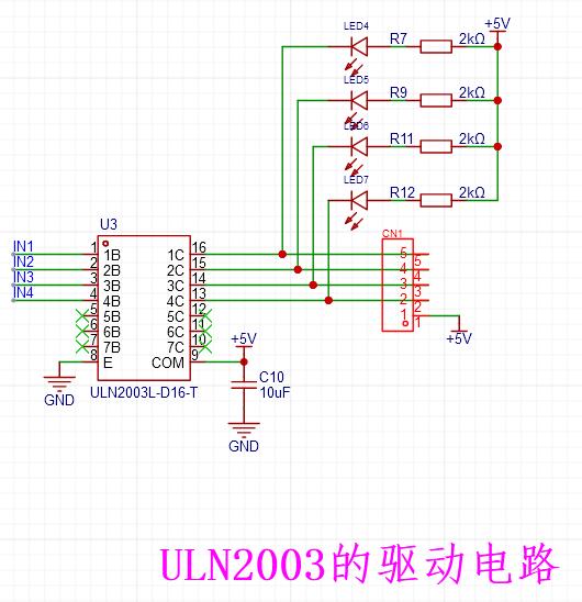
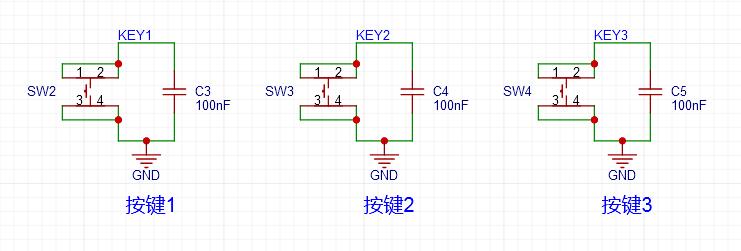
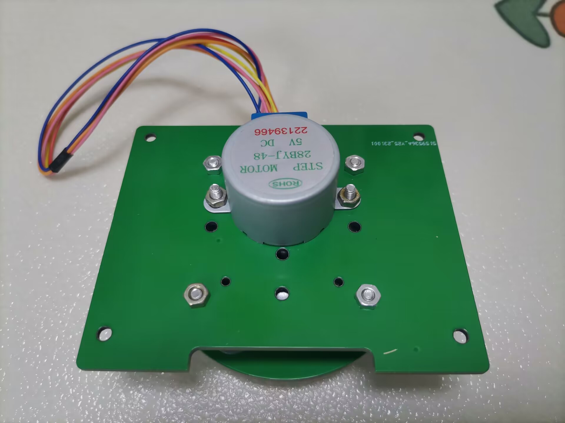
13. A rotating gimbal expansion board has been added. This circuit is powered by a separate 2S lithium battery and has a reserved control interface for connection to the main control board. The circuit includes a DC-DC 5V step-down circuit, an LDO 3.3V voltage regulator circuit, a 6-channel MOS-controlled power output circuit (2 channels 3.3V, 2 channels 5V, 2 channels VIN), a ULN2003 driver circuit (used to drive a 28-stepper motor), and 3 push-button switches.
14. The stepper motor rotating gimbal uses a 28-stepper motor, connected to the rotating part of the gimbal via a hollow turntable bearing. It can be fitted with a water gun or other character equipment. The physical component is now complete and has undergone power-on testing. 360-degree rotation is smooth. The only remaining issue is a misalignment between the motor shaft and the upper part of the gimbal. This is because the fixing screws are obstructed by the bearing, preventing a tight fit and affecting the accuracy of the water gun firing. Therefore, this gimbal will not be installed for now; this issue will be addressed later.
Design Principles
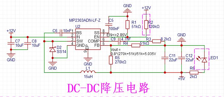
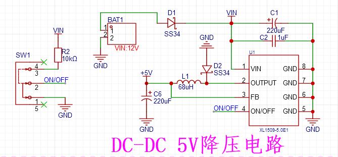
: 1. The system's voltage regulator circuit uses a DC-DC step-down circuit with an input voltage range of 4.7V to 28V (this project uses three 18650 batteries for power). The maximum output current is 3A, and in this project, the output voltage is 5V to power the entire system.
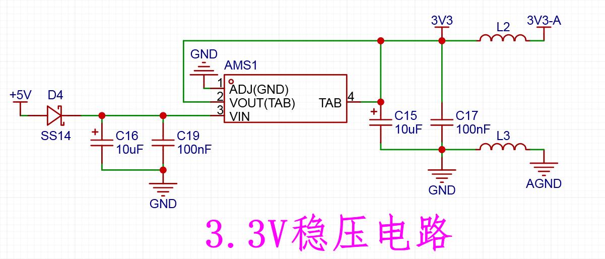
2. The LDO voltage regulator circuit uses an AMS1117-3.3, primarily for powering the microcontroller and some low-power peripherals.
3. The main controller uses an STM32F103R8T6, mainly due to its numerous pins and readily available online resources, facilitating development.

4. An L293D is used as the motor driver, with wide voltage input/output and PWM speed control.
5. Level conversion circuit.
6. Two power supplies controlled by MOS.

7. Buzzer Driver Circuit.
Below is the circuit diagram for the rotating gimbal expansion board
: 1. Also a DC-DC step-down circuit, default output 5V.
2. MOS-controlled power output circuit, output voltage VIN, one for low-power output, one for high-power output.
3. MOS-controlled power output circuit, output voltage is divided into 3.3V and 5V, two of each.
4. Stepper motor driver circuit, using ULN2003L as the driver chip, can drive a common 28 stepper motor.
5. Three push-button switches have been added to expand some functions that require setting or start/stop.
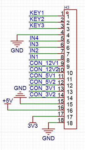
6. Wiring terminals for the expansion board. Connect to the main control board using DuPont wires as needed.
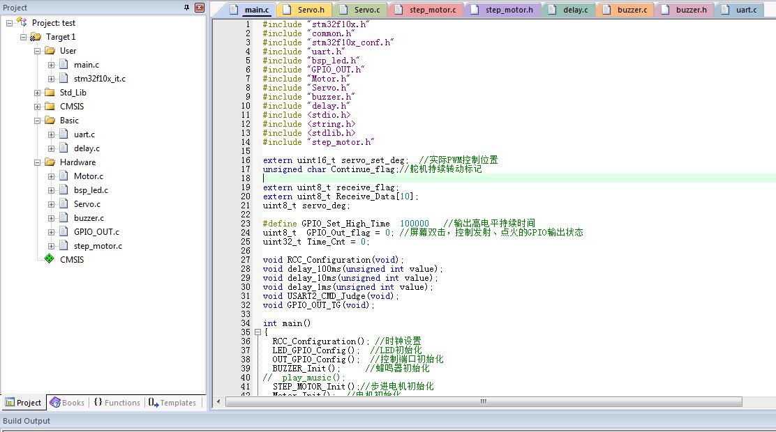
Software Description:
1. The program
is developed using KEIL software. It mainly receives data from the wireless router's serial port and parses it, performing corresponding actions based on the parsed commands. Only a portion of the content is shown here.
The program is attached; please download it.

2.
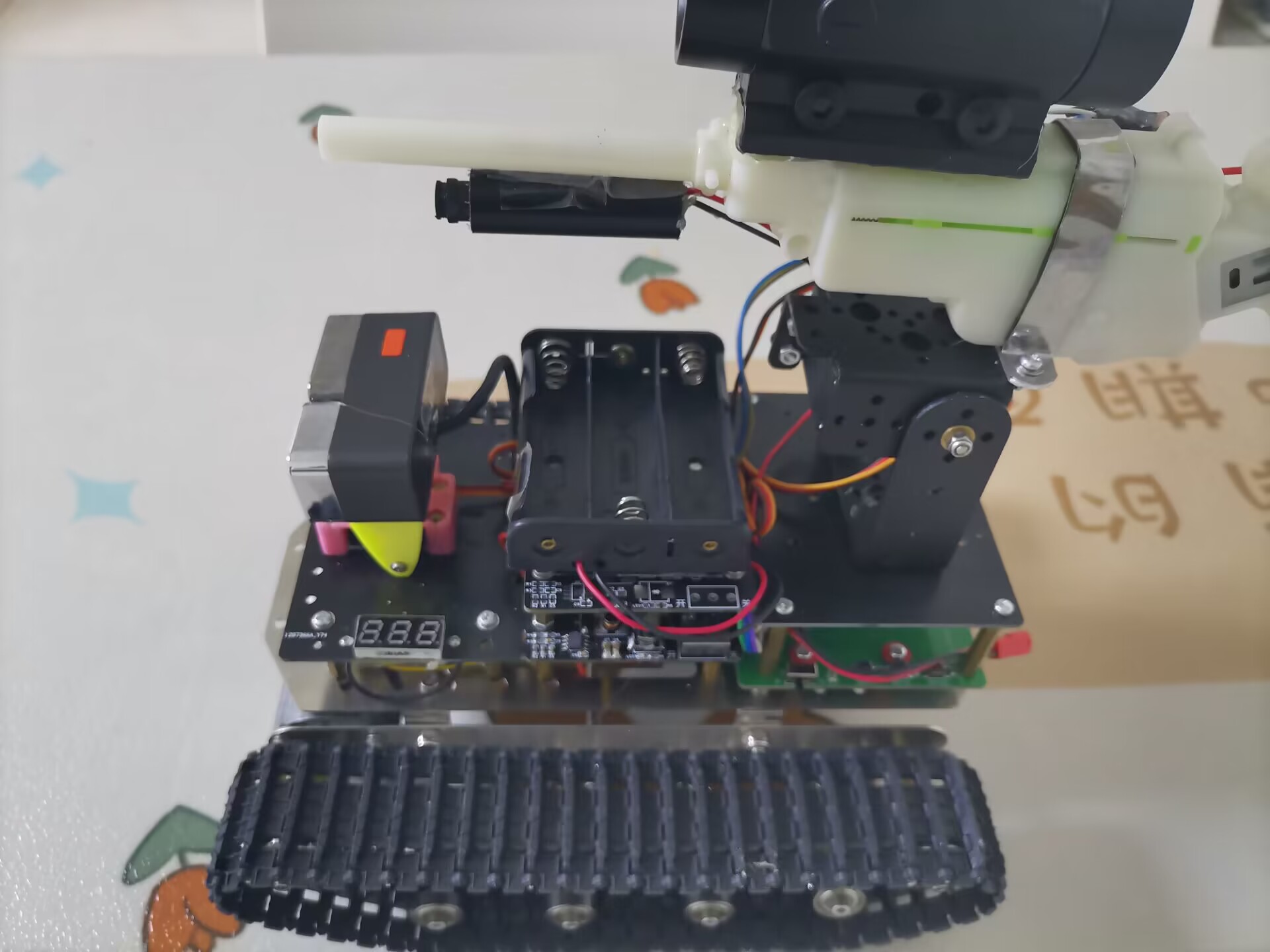
Due to limited capabilities, I directly used an existing app. Search for "wifirobot" online, or download it from this link: https://www.muzhijita.com/apk-fk-5020.html. Here are some additional photos of the rotating gimbal for

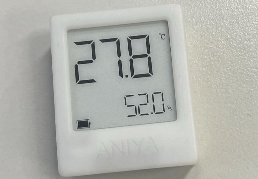
physical demonstration. Design Notes: 1. The water gun should not be fired at people, and the water bullets should not be given to children to play with, to avoid accidental ingestion. 2. Do not use infrared lasers to shine into people's eyes, to avoid injury. Other points to note: The tracked vehicle chassis, including the wireless router and camera, were purchased secondhand from Xianyu (a second-hand marketplace). The corresponding products are no longer available online, so I do not recommend that users replicate them. Additionally, this project uses the Xiaor Technology wifirobot app. Due to potential copyright issues, only the relevant webpage link is provided here; the app software is not provided. I suggest that users with the capability develop their own apps.

QQ Video 20231010110208.mp4
QQ Video 20231010110201.mp4
QQ Video 20231010110158.mp4
QQ Video 20231010110155.mp4
QQ Video 20231010110134.mp4
Tracked vehicle.hex
ST WIFI Tank_20231001.rar
PDF_Multi-functional Tracked Vehicle.zip
Altium_Multi-functional Tracked Vehicle.zip
PADS_Multi-functional Tracked Vehicle.zip
BOM_Multi-functional Tracked Vehicle.xlsx
91039
Blheli_s 8S60A ESC
Open source high-power inductive square wave ESC 36V 60A continuous
The open-source high-power sensorless square wave ESC using BLHeli_s JH-05 firmware
has a maximum operating voltage of 36V.
Recommended operating voltage: 8S (Li-Po) or 24V (switching power supply).
Maximum operating current: 60A for 10s (motor end, untested), 15A continuously (motor end, tested).
Due to limited tools, detailed testing was not conducted. With good heat dissipation, 30A continuous should be fine.
*Regenerative braking is always enabled; please handle regenerative current carefully, otherwise a boom may occur.
Supported input signals:
Analog: 1-2ms PPM, Oneshot125 (125-250us), Oneshot42 (41.7-83.3us), Multshot (5-25us); Digital signals: Dshot150, Dshot300, and Dshot600.
When flashing the Bluejay firmware, bidirectional Dshot RPM feedback is supported
(if you don't understand this, you are not a racing game enthusiast; you can ignore this and directly use servo signals for drive).
Supports motor forward/reverse rotation and advance angle adjustment.
Onboard 5V 1A. BEC can power the receiver but is not suitable for servos.
It is suitable for various brushless motors, and its applications include but are not limited to fishing boats, large drones, RC models, and large fans (!?). Please explore its various uses yourself.
Firmware burning guide:
Recommended: Use Arduino Nano (other me


 京公网安备 11010802033920号

 EE06-FT1E4-K300


