
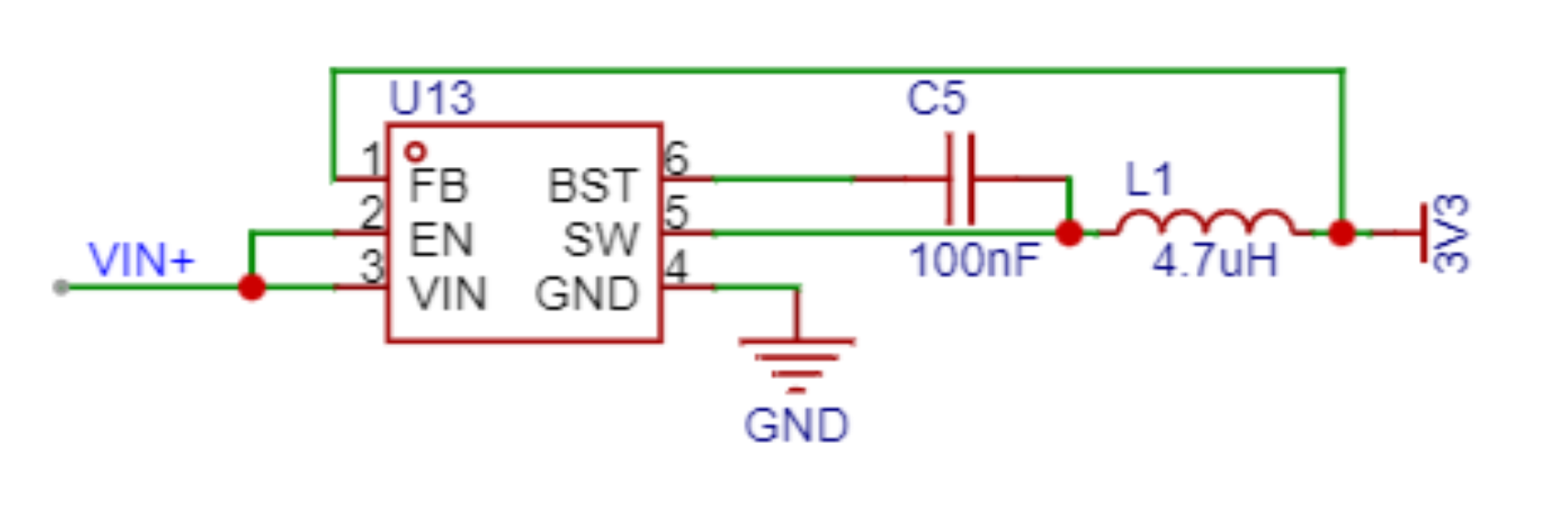
 An AP63203 DC-DC converter is used, with a fixed 3.3V output. However, this power supply design had a slight mishap. The AP63203 DC-DC datasheet states a 3.3V output, but the actual output is about 0.1-0.3V higher, causing the ST7735 screen to display incorrectly when the input voltage is high. Fortunately, the solution is simple: short-circuit the 3.3V and 5V on the development board. Testing showed that after short-circuiting, the output was 3.4V with a 20V input, but this did not affect operation.
 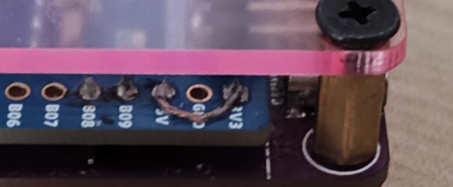 Note: After short-circuiting, never use the development board's built-in Type-C
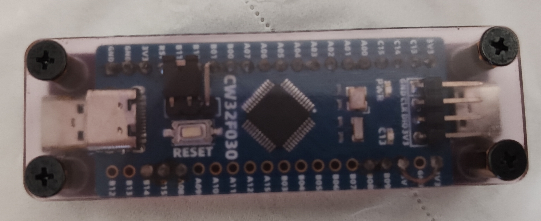
 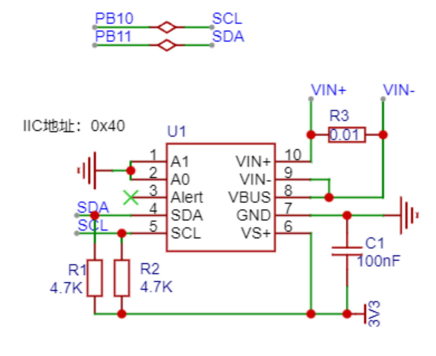 main control MCU
  . The display screen
 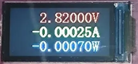 . Software components:
 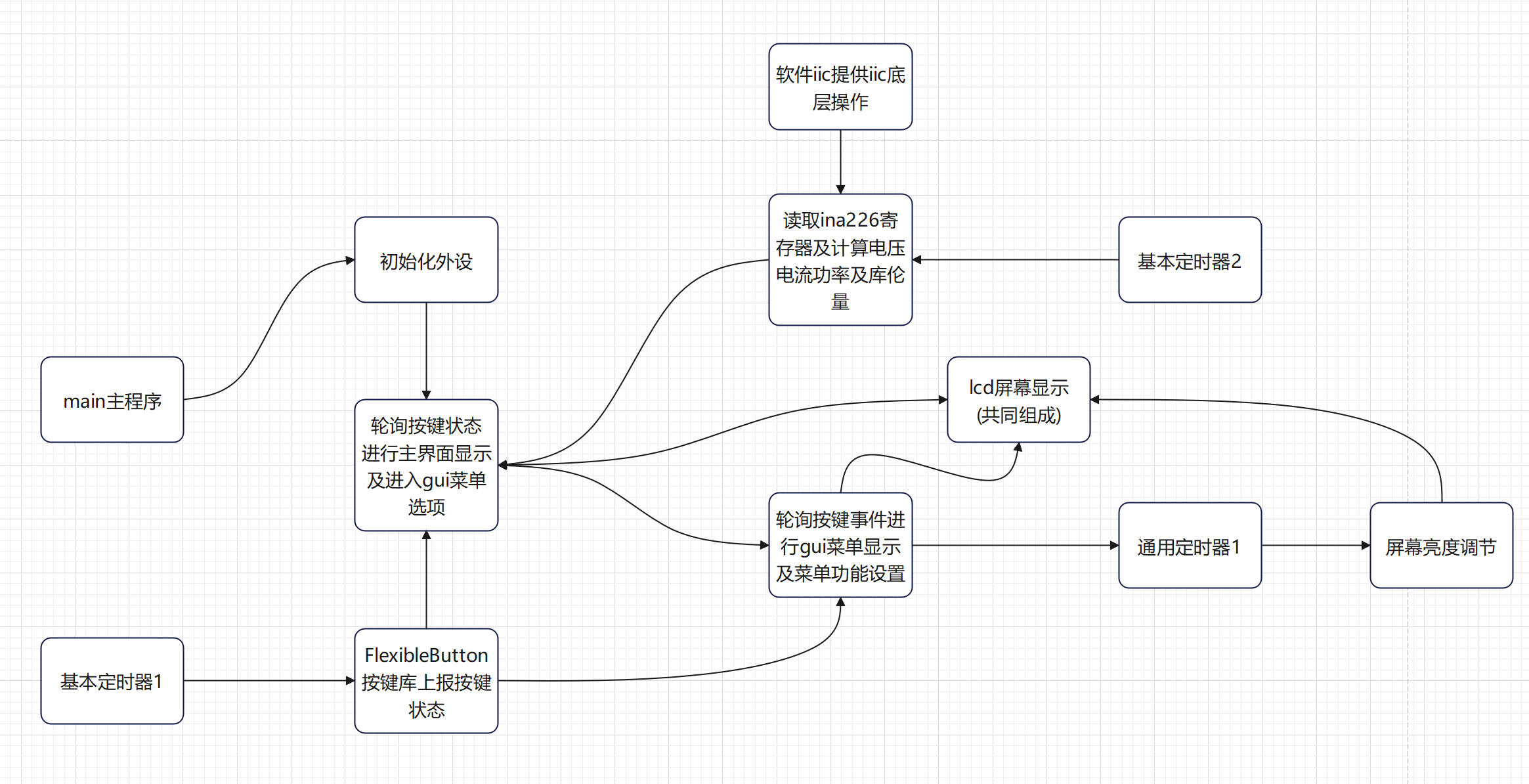 See source code: https://gitee.com/xmqor/cw32f030-mini-usb-voltage-ammeter
 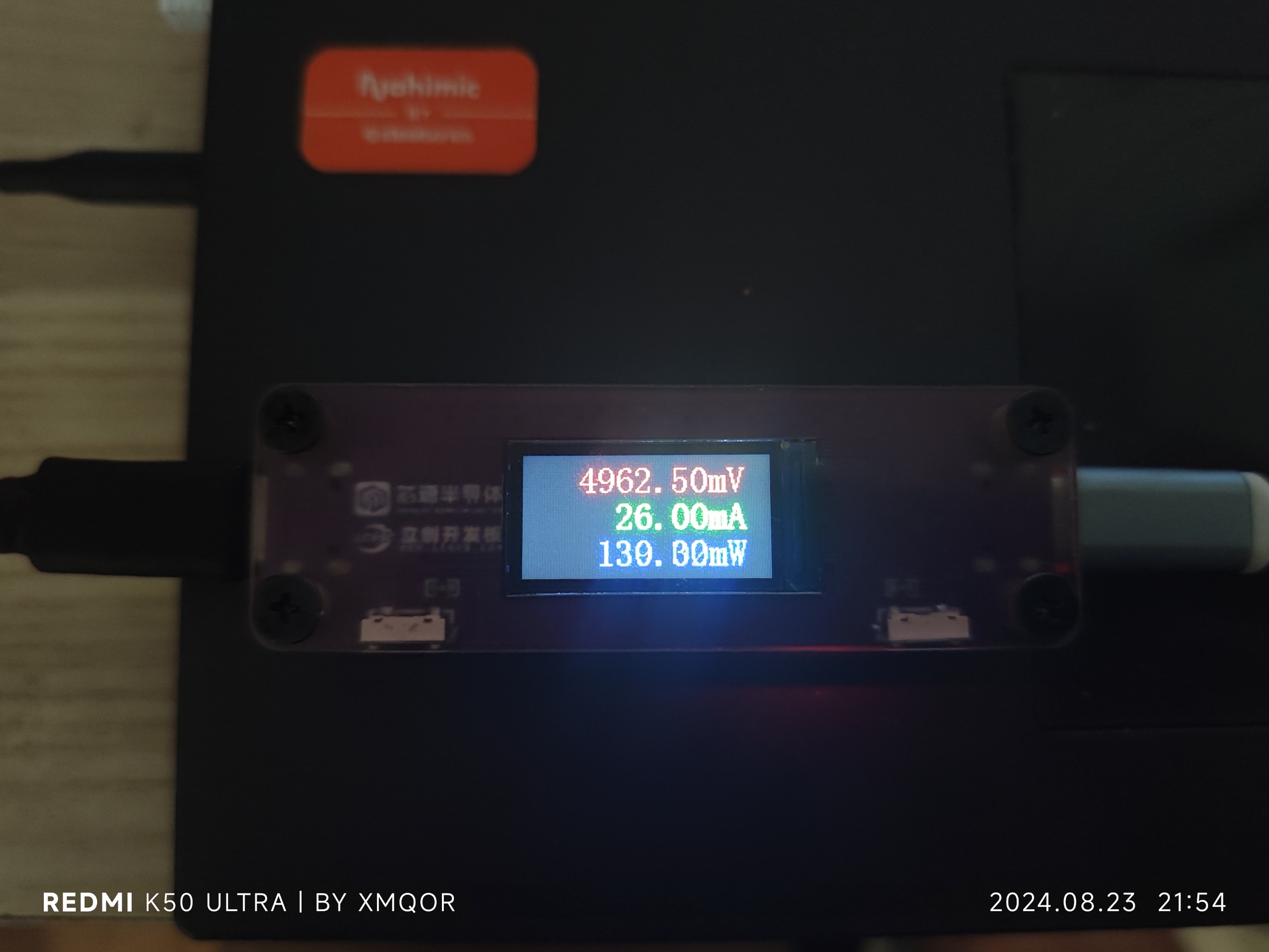 Coulomb meter: The coulomb meter samples power 100 times per second via a timer and calculates the integral.
 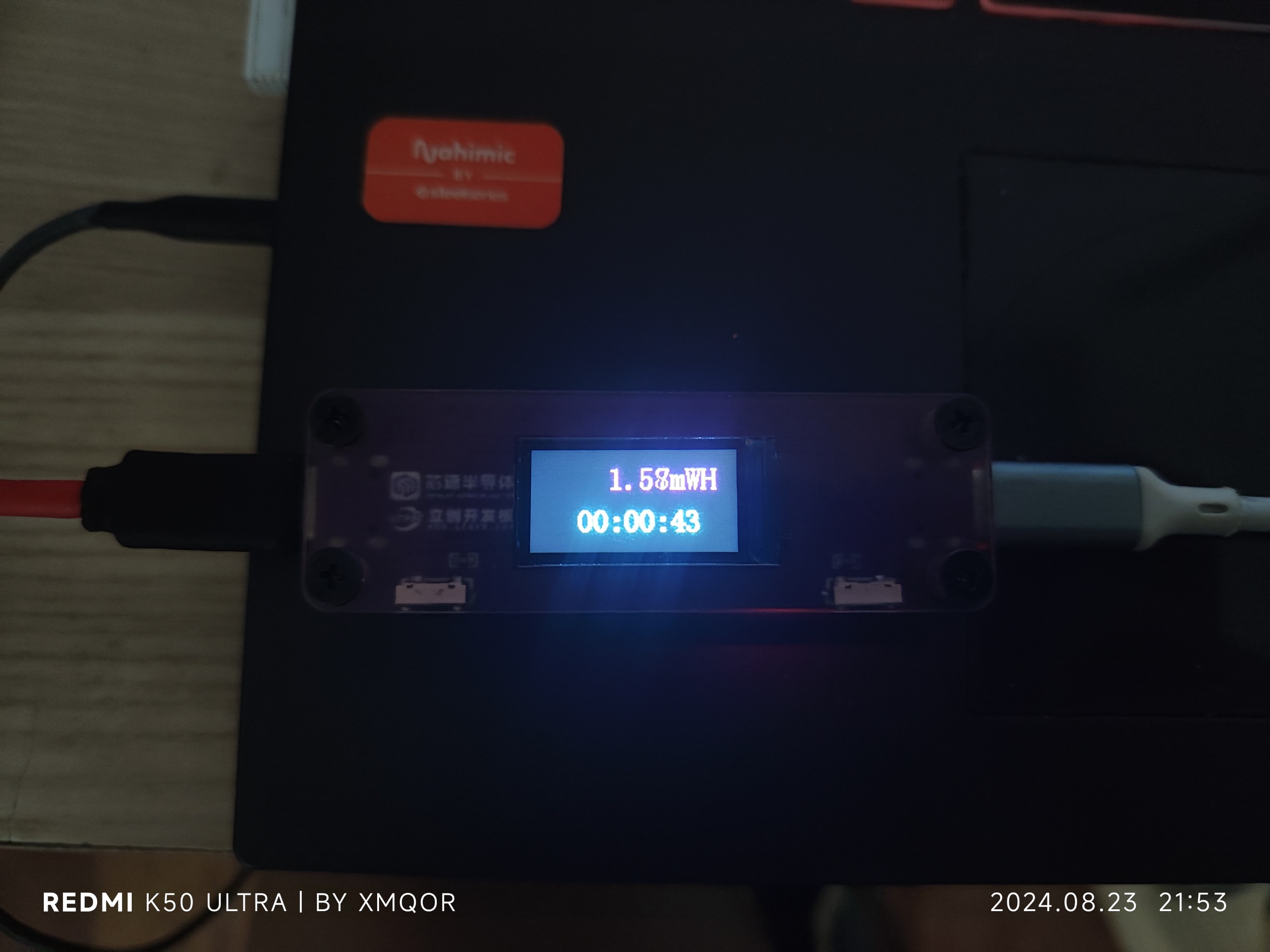 UI menu:
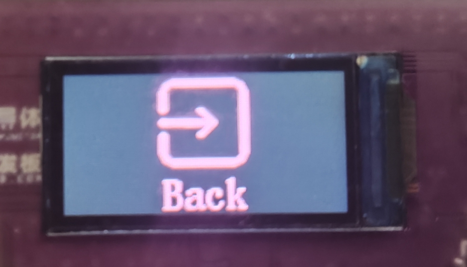
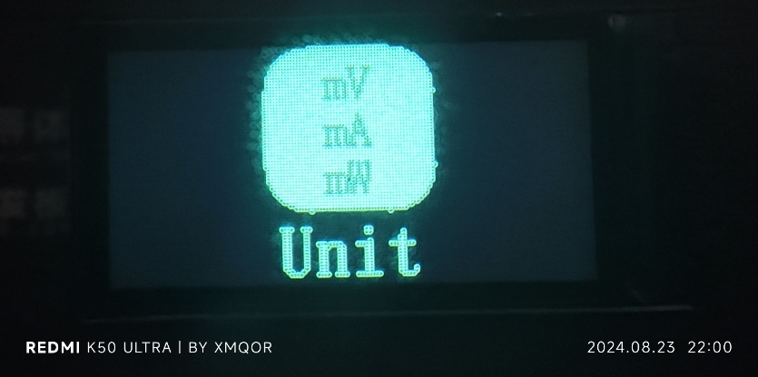 UI operation instructions:
  screws and nuts as spacers. Buy the size shown below.
  The printed panel is semi-transparent, and the text is very unclear. If you don't like it, adjust the transparency control layer yourself.
All reference designs on this site are sourced from major semiconductor manufacturers or collected online for learning and research. The copyright belongs to the semiconductor manufacturer or the original author. If you believe that the reference design of this site infringes upon your relevant rights and interests, please send us a rights notice. As a neutral platform service provider, we will take measures to delete the relevant content in accordance with relevant laws after receiving the relevant notice from the rights holder. Please send relevant notifications to email: bbs_service@eeworld.com.cn.
It is your responsibility to test the circuit yourself and determine its suitability for you. EEWorld will not be liable for direct, indirect, special, incidental, consequential or punitive damages arising from any cause or anything connected to any reference design used.
Supported by EEWorld Datasheet
EEWorld
subscription
account

EEWorld
service
account

Automotive
development
community

Robot
development
community

About Us Customer Service Contact Information Datasheet Sitemap LatestNews


Room 1530, 15th Floor, Building B,
No.18 Zhongguancun Street,
Haidian District,
Beijing, Postal Code: 100190
China
Telephone: 008610 8235 0740
 京公网安备 11010802033920号

 HLMP-3416-MQ401


