I found an article on Zhihu that mentioned using a constant current source for a voltage reference to improve its accuracy.
This module is just for testing purposes, and the provided resistance values may not be usable. Please use software simulation before building.
#7th LCSC Electronics Design Contest# USB Power Meter and QC-Tricked Adjustable Power Supply
USB power monitoring was implemented using the N32G430. MAX: 20V 2A. USB 2.0 pass-through supported. Includes QC3.0 spoofing simulation and DC current limiting protection output.
1. Project Function Introduction:
This project was submitted to the LCSC training camp.
Maximum input 20V 3A. Implements USB power and ripple detection. Supports USB 2.0 passthrough or QC3.0 decoy. DC buck current limiting output.
The power supply section uses a DC-DC to 3.3V converter to power the system. It uses the MT2492, which, although nominally rated at 12V, can still output 3.3V normally at 19V in actual testing.
Voltage detection uses an internal 12-bit ADC, and current detection uses an INA199 with a 10mΩ resistor differential-mode amplified 50 times before being converted to an internal 12-bit ADC.
2. Project Attributes
: First public disclosure
. Original reference to this project:
[Open Source] High-Precision QC3.0 Decoy_Bilibili_bilibili
Xie Ming used the line drawing function of this graphics library. Microcontroller Graphics Library Open Source Sharing 32 51 OLED_Bilibili_bilibili
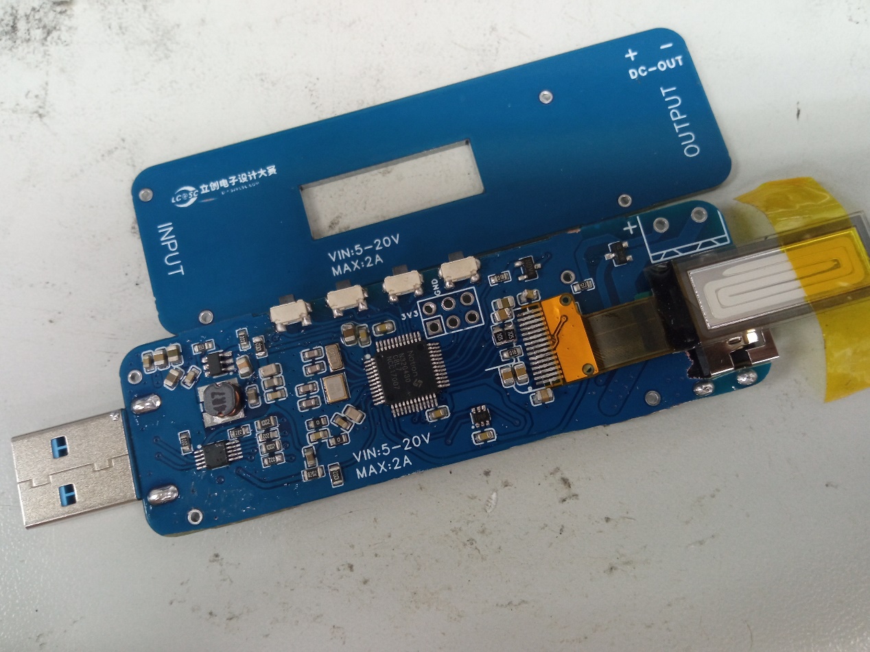
3. Hardware Part:
Hardware Structure Diagram

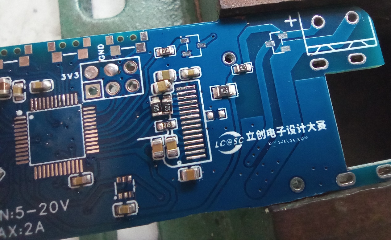
A. First is the minimum system of the single chip.
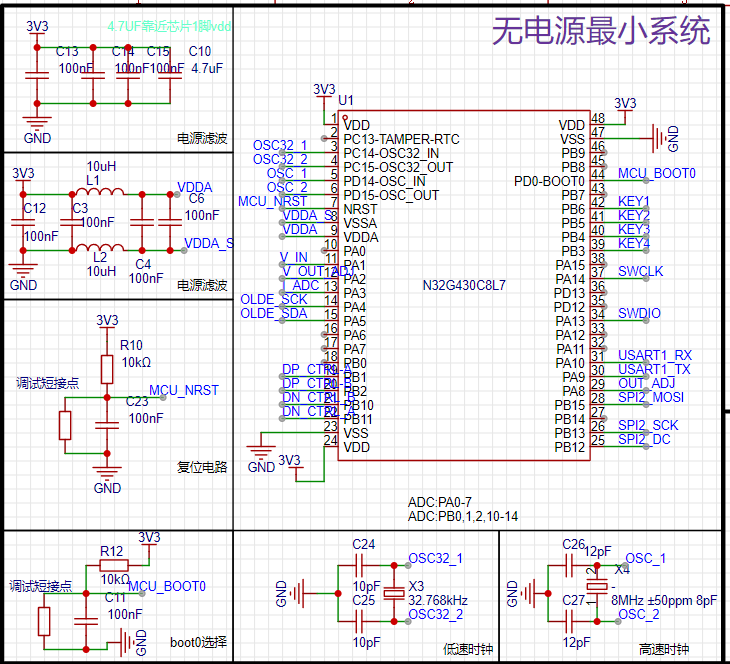
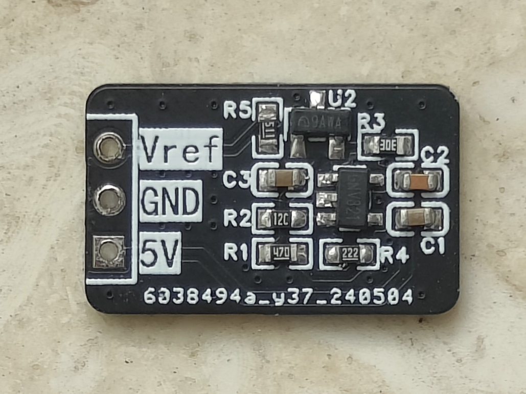
This is relatively standard; just follow the reference materials. It's worth mentioning that, to save costs, a reference power supply IC was not used; instead, a filter was added before connecting it to the ADC reference input. The BOOT0 boot partition selection and RST are only soldered with 0603 resistors, with external buttons attached. This allows for disassembly and adjustment after program debugging, improving the appearance.
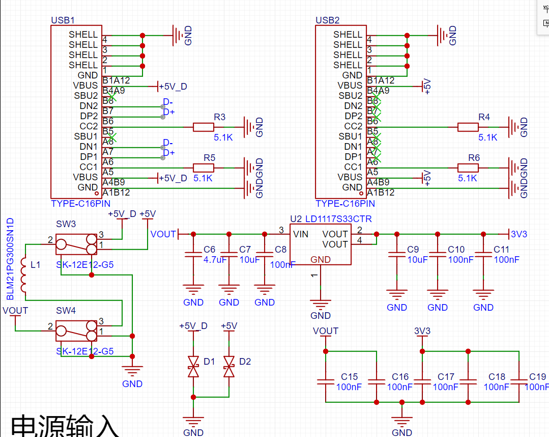
B. The module power supply section
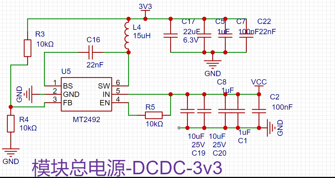

drops from 20V to approximately 0.5V, demonstrating excellent MCU protection. It has a sufficiently wide voltage tolerance and is fully compatible with QC3.0's 12V.
C. For programming and interactive

programming, UART serial programming and SWD are introduced. SWD is recommended for one-click programming in Keil. UART requires downloading the National Technology download software. Furthermore, UART cannot be debugged.
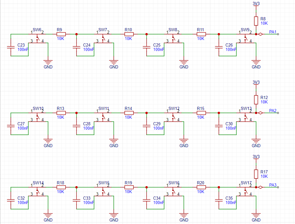
For human-machine interaction, four buttons are used. A better solution is to connect one end of each button to I/O and the other end to ground, referencing National Technology's development board. A 100nF capacitor can be connected in parallel with each button for filtering.
A 0.91µm SPI screen is used for display. It has to be said that the experience of 128x32 is significantly worse than 128x64. The drawing area is halved, and many displays are rather haphazard. The driver used is the sample project software SPI from the purchased website, and I rewrote the character drawing and other functions myself. Thanks again to the graphics library provided by the developer; I copied and adapted a line drawing function from it. The screen hardware is actually connected to the MCU hardware SPI pin; I'll work on that later when I have time.
D. The core sampling function
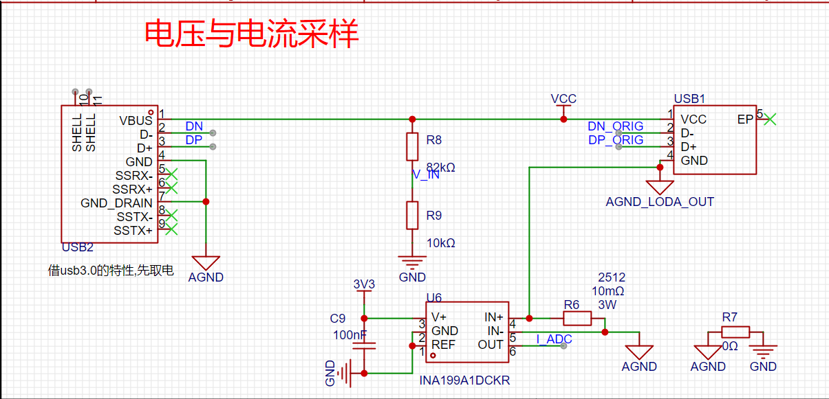
calculates power by collecting the input voltage and the current on the bus.
The voltage is divided by resistors and then connected to the ADC pin.
The current is amplified 50 times by the differential mode voltage of the 10 milliohm sampling resistor using the INA199 before entering the ADC pin. A small design detail: the MCU system is connected after the low-end sampling resistor to avoid the influence of the microcontroller system on the load power sampling.
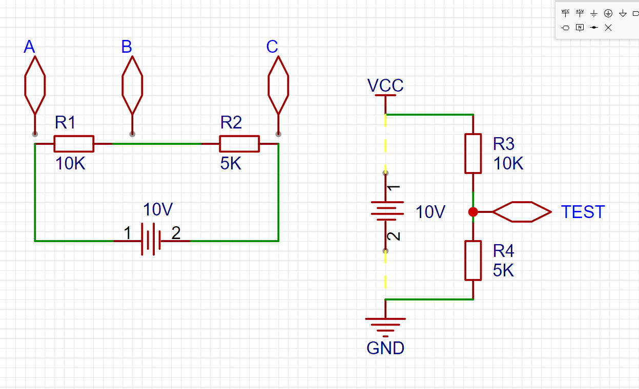
Using the voltage range of a multimeter, we can measure the voltage difference between any two points. Note that it's the voltage difference between two points. For example, in the above diagram, we would say that Uab voltage is 6.66V, and Ubc = 3.333V.
In Uxx, we use the latter voltage as a reference, such as Uab, which is actually Ua-Ub.
What is Ua?
It's the voltage at point a relative to 0V
. Where is 0V defined? Generally, it's anchored to the negative terminal of the power supply. (When doing calculations, you can arbitrarily set the voltage at a certain point to 0V and use this anchor point for calculations).
Therefore, in this electronic system, you'll find the representation in the diagram on the right to be so natural.
If you still don't understand, you can think of it as always keeping the black probe of the multimeter pressed against the negative terminal of the battery.
The voltage at point test can be calculated using voltage divider:
Utest = VCC * 5 / (10 + 5)
. If VCC = 10, then Utest = 3.33V. (The calculation approach here is based on a series resistor; the current is constant, and Ohm's law is used to derive the calculation.)
Conversely, if Utest = 1V is known... Therefore,
VCC = Utest ÷ [5/(10+5)] = 3V.
The microcontroller's ADC is like "the black probe of the multimeter always touching the negative terminal of the battery," and the ADC pin is the red probe.
Now, let's formally explain the calculation coefficient.
Using my example,

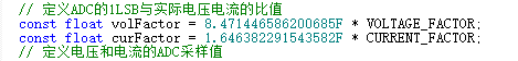
as shown in the figure, the actual ADC sampling value is 679.
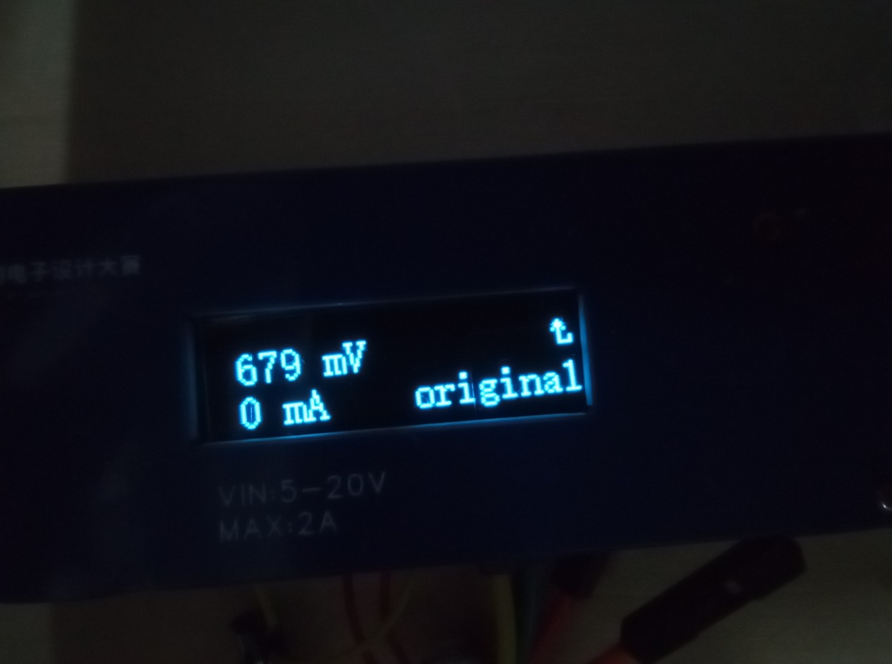
What does this ADC value mean?
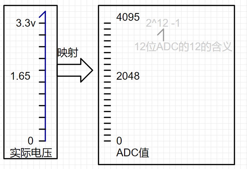
So, the ADC=679 comes from

ADC=Utest/3.3 *4095= 679.
We can work backwards to get
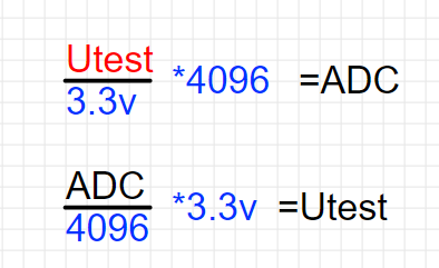
Utest=ADC ÷4096*3.3=0.547V.
Then, combining this with the previous resistor voltage divider,
Vcc= Utest÷[10/(10+82)]=5.03V, we
can further refine this:
Vcc= Utest÷[10/(10+82)]
Vcc= (ADC ÷4096*3.3) ÷[10/(10+82)].
Then, we simplify the constants:
Vcc=ADC* (7.4121X10^-3); Vcc=ADC*0.0074121 (volts);
If you have prior programming experience, you'll know that floating-point calculations have errors. Therefore, we multiply the coefficient by 1000, changing the output unit from volts to millivolts.
Vcc=ADC*7.4121; This is very close to the example. But why is it still different? That's because the MCU's ADC sampling has a bias. For an explanation, see page 74 of the datasheet (not the user manual; there are two PDFs with different focuses)
. Also, make good use of search engines.

Next is current acquisition. Here, the INA199's 50x differential voltage amplification is used. "Differential mode" can be understood as the voltage measured by pressing the multimeter probes across a resistor.
Knowing the voltage across the resistor, the current can be calculated using I=U/R; I won't elaborate further here.
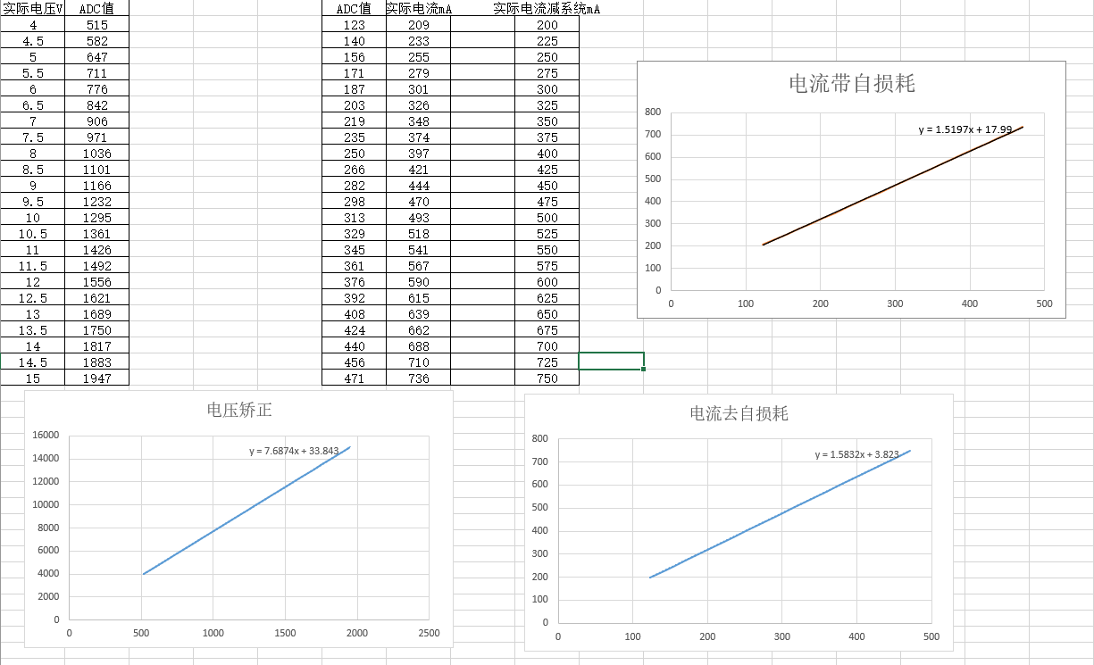
To correct the bias, I used an adjustable power supply coefficient correction. It's quite close to the theoretical calculation. (To achieve this, search for Excel fitting curves yourself.)
D. QC Deception and Channel Switching

. On the left is a USB 2.0 analog switch IC. Using a USB 3.0 male connector ensures the system powers on first and starts working, defaulting to USB 2.0 input/output. As you can see in the schematic, my positive and negative terminals don't match the IC; this is for easier routing in the physical PCB. The datasheet specifies rail-to-rail, which is why I dared to do it this way. Regarding the QC3.0 charging protocol, please search for information yourself.
4.
The main structure of the software is roughly as follows: A detailed demonstration video

will be provided on Bilibili later .
[LCSC Training Camp USB Power Meter - Bilibili] https://b23.tv/eCdln06
END. Project and LCSC Electronics Contest logo display.


PDF_#7th LCSC Electronics Design Contest# USB Power Meter and QC-Tricked Adjustable Power Supply.zip
Altium_#7th LCSC Electronics Design Contest# USB Power Meter and QC-tricked Adjustable Power Supply.zip
PADS_#7th LCSC Electronics Design Contest# USB Power Meter and QC-tricked Adjustable Power Supply.zip
BOM_#7th LCSC Electronics Design Contest# USB Power Meter and QC-induced Adjustable Power Supply.xlsx
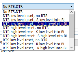
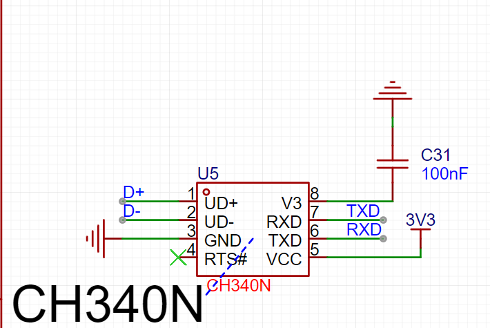
The GD32F130C6T6 minimum system board features an onboard CH340 serial port download circuit. It can be programmed using either GD32AllInOneProgrammer or STLink. When using GD32AllInOneProgrammer for serial programming, you need to select DTR LOW and RTS HIGH each time you open the software to enter the BootLoader.
Using salvaged chips may encounter flash protection issues preventing programming; GD32AllInOneProgrammer can remove this flash protection.
Onboard LEDs are connected to PC13 (low level lights up), and onboard buttons are connected to PB2 (pull-down, high level when pressed, do not press during startup).
The project was imported from an offline standard version, so theoretically there shouldn't be any problems; the current verification is based on a previous standard version project.

PDF_GD32F130C6T6.zip
Altium_GD32F130C6T6.zip
PADS_GD32F130C6T6.zip
BOM_GD32F130C6T6.xlsx
94531
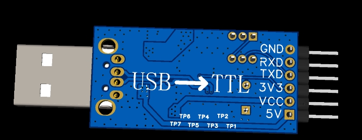
Unisolated USB to TTL converter supports 5V and 3.3V voltage levels.
USB to TTL programmer, stable output level, no board damage. Also supports one-click cable replacement.
I. Team Introduction
Personal: Shenlong Zaizai
II. Development Background
It's truly frustrating. I bought so many USB to TTL adapter modules, it's driving me crazy. Burning circuit boards, burning serial ports... they all break down after a few days. Although they're quite cheap, the constant failures are unbearable! I designed my own serial programmer that can stably output TTL levels, so it can be used continuously, infuriating those unscrupulous vendors (who send broken products and refuse returns).
These are actually quite cheap, probably less than 3 yuan each, while a CH340G chip might cost more. Indeed, in the industrial electronics era, the cost of transporting materials is higher than the materials themselves.

But today I want to talk about its problems.
First, its advantages:
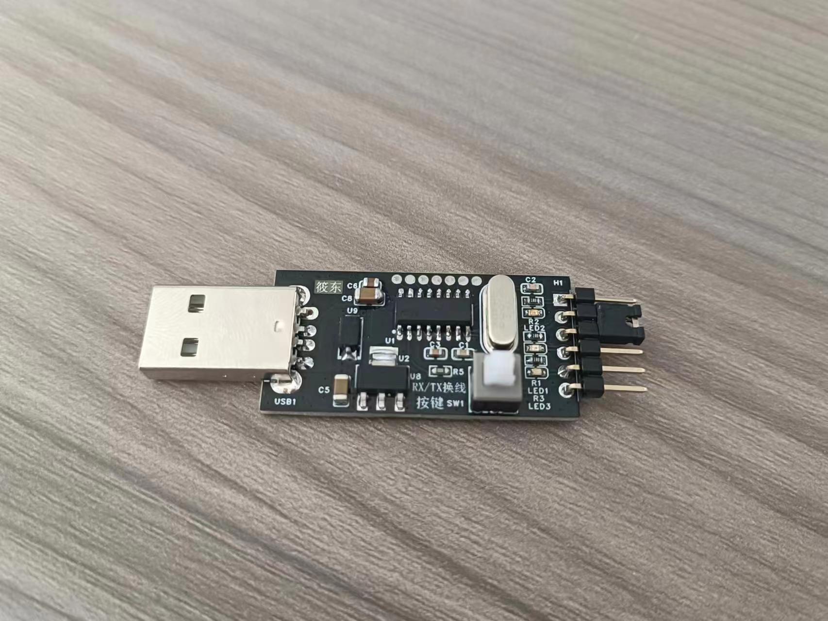
The design idea of this module is a classic one, integrating the 3.3V and 5V power supply outputs of the CH340G chip, corresponding to 3.3V and 5V levels. The materials used are top-notch (saving costs). The output TTL signal level voltage can be converted using the yellow jumper cap on the back.
It's perfectly compatible with all STC microcontroller series, unlike the PL2303 solution which has download issues due to driver problems (this is very stable).
It not only has a power LED but also TXD and RXD LEDs, making it easy to visually check if communication is working properly during product use.
It supports 32-bit or 64-bit systems like WIN7/WIN8/WIN10/SERVER 2008. It cleverly utilizes the two 4148 chips shown in the diagram to complete the 5V to 3.3V (normally 3.4V).
Now for its drawback:
the critical flaw of this module lies in the cost-effective voltage conversion of these two 4148 chips.
Normally, with a 5V input, the voltage is reduced by using two diodes and their internal resistance voltage drop (approximately 0.7V). In high-voltage applications, multiple diodes are usually connected in series for voltage division. However, in practical applications, it's unclear whether this is a problem with the 4148 chips themselves, or if some manufacturers use high-quality 4148 chips (with small voltage drops). This can cause abnormal output voltage. The highest I measured was around 3.7V, and the lowest was when the module suddenly stopped working. (The reason was that there was a voltage between one of the diodes and another diode, causing one of the diodes to remain off and not conduct. I measured the voltage with a multimeter, and it worked again. The module's power indicator light came on.) If you encounter this module malfunctioning, you can test it. Generally, the CH340G chip is quite reliable (unless the firmware is lost).
Getting back to the main point, experienced technicians know that if you read the manual, you'll find that whatever voltage VCC provides, the corresponding RX and TX voltage levels are roughly the same. If this voltage level is higher than 3.6V, it will definitely burn out. Secondly, when the serial port is sometimes not used or needs to be disconnected, we usually only disconnect the USB end. In this case, the board will supply power in reverse (I suspect that my abnormal voltage was caused by this, resulting in abnormal voltage levels across the diodes and preventing them from working).
The faults of this product are basically all in the diodes. If you measure the diodes individually, they are fine; a voltage of 5V is not enough to break down and damage the diodes. However, if you measure the chip's input voltage under USB power, you'll sometimes see no 3.3V input, and the power indicator light will be off. But when you measure the voltage between the two diodes to ground, the module will magically light up again. It's not a matter of discharging or removing power. (I've tried this; this indicates a damaged diode, and I recommend replacing it. However, I've found that new diodes might be of very high quality (low voltage drop), resulting in a very high 3.4V output voltage, so be careful.) In other words,
if it's not broken, why would you buy a new one? If the indicator light doesn't light up, you assume it's faulty and replace it. If the computer can't find the driver or it doesn't pop up, you assume it's faulty. Actually, it's all a problem with the diodes; unstable or abnormal power supply leads to abnormal output.
III. Design Summary:
I wanted to improve this aspect to make the 3.3VTTL stable and avoid burning out the board's serial port.
For easier testing, I added a one-click cable switching function, making it convenient to switch the RX and TX lines by pressing a button in case of incorrect connections.
I don't want to be ripped off anymore. Even though it's not expensive individually, my board is expensive, and I only have one for testing. If it breaks, I have to fix it myself.
IV. Problem Analysis
and Reference Technical Manual: I found that the V3 pin of the chip
is best used to control the TTL 3.3V input voltage; otherwise, it's prone to failure.
Other pins are rarely used, so I've designed them to be exposed for those who need them. Those who don't need them can leave them as is; they look nice.
V. Overall Design Block Diagram

: Below is the schematic diagram for design reference.
When designing, pay close attention to the V3 pin.
VI. Hardware Circuit Composition:
First and foremost, modify the power supply to ensure a stable 3.3V output. 5V USB power is actually quite stable. My first design used an LDO + diode reverse current protection design, but the voltage was too low. It only reached 2.7V and couldn't pick up.
Later, I switched to a diode + LDO. Testing showed that the LDO could supply 5V in reverse without problems. I was initially worried about the LDO being sensitive to reverse power supply, so I designed it that way. Therefore, what you see here is the second, improved version.
The LDO is powered by 5V single-phase power, and the actual measured output voltage is around 4.6V (1117-3.3). In actual use, it can output 3.3V normally, which is very stable. The power supply is solved.
The one-click cable replacement function uses a double-locking switch to achieve RX/TX switching of the output, which is perfect and has been tested.
VII. Program Flowchart:
Pure hardware, no software, and no software operation interface.
VIII. Physical Display:
The back looks a bit abrupt, but it is indeed the smoothest way, and the relationship and direction are consistent.
The physical product is still good.

IX. Precautions :
1. Other designs are reserved on the board, and I have perfectly integrated the two LDO packages.
2. In order to make others' paths unusable, a compatibility design has been made. It is also possible to use a diode + diode step-down method. As long as you think it is okay, I will not force everyone to use it. It is up to you. It is mainly for friends who need to replace broken modules. You can directly port it to my board to experience the one-click cable replacement function and other pins.
3. V3 requires special attention to the pin connection method. I've seen some open-source projects neglect this. When designing for 5V and 3.3V compatibility, they need to consider reverse power supply and shared power issues, just like I have.
4. Let's exchange ideas if we have any questions. I hope vendors will see this too. This is really painful!
X. Demo
Video I've put the demo video at the end; the effect is very good. Recorded with one hand, please understand.
Serial Port Assistant.zip
WIN7 64-bit USB to Serial CH340 Driver.rar
USB to Serial Port - BOM_.xlsx
Serial Port Debugging Assistant.zip
Communication test, one-click cable switching test.mp4
LLT Level Voltage Test.mp4
PDF_Non-isolated USB to TTL supporting 5V and 3.3V levels.zip
Altium_Non-isolated USB to TTL supports 5V and 3.3V levels.zip
PADS_Non-isolated USB to TTL supports 5V and 3.3V levels.zip
BOM_Non-isolated USB to TTL supports 5V and 3.3V levels.xlsx
94532
Direct-plug RP2040 six-axis 3D printer motherboard
A stable, high-performance 6-axis 3D printer motherboard with direct-plug RP2040 chips (this was built using my existing parts and can be modified to have a larger MOSFET) (I rarely use 3D printers anymore).
This is a stable, high-performance 6-axis 3D printer motherboard with direct-plug capability, based on the JLCPCB RP2040 direct-plug king version: https://oshwhub.com/yoshino/rp2040-spi-tong-xun-da-yin-ji-zhi-cha-jian-zhu-ban. It's soldered onto my own 0.1 and TT printers and is compatible with printers like the BigFish TT and CC, Gugu Chicken, Voron 0.1, and Trident, but only works with Klipper and not Marlin. My own Voron 0.1 and TT printers have been used for approximately 300 hours. The motherboard operates at 12-24V, with a maximum current support of 20A for the heated bed interface and a maximum output of 10A for the extruder heating rod interface. Configuration: 1. Full-axis UART support: Compatible with TMC2209/2208/2225/2226 and other UART drivers. 2: Three controllable fans; 3: Two thermistors; 4: Three limit switches and one probe limit switch with optical isolation, the probes support NPN and PNP; 5: The heated bed, heating rod, and fans all have optical isolation (the MOSFET for the heated bed thermistor can be matched with different power ratings).
1285164291.mp4
RP2040 configuration file.txt
PDF_Direct-plug RP2040 Six-Axis 3D Printer Motherboard.zip
Altium_Direct-plug RP2040 Six-Axis 3D Printer Motherboard.zip
PADS_Direct-plug RP2040 Six-Axis 3D Printer Motherboard.zip
BOM_Direct-plug RP2040 Six-Axis 3D Printer Motherboard.xlsx
94534
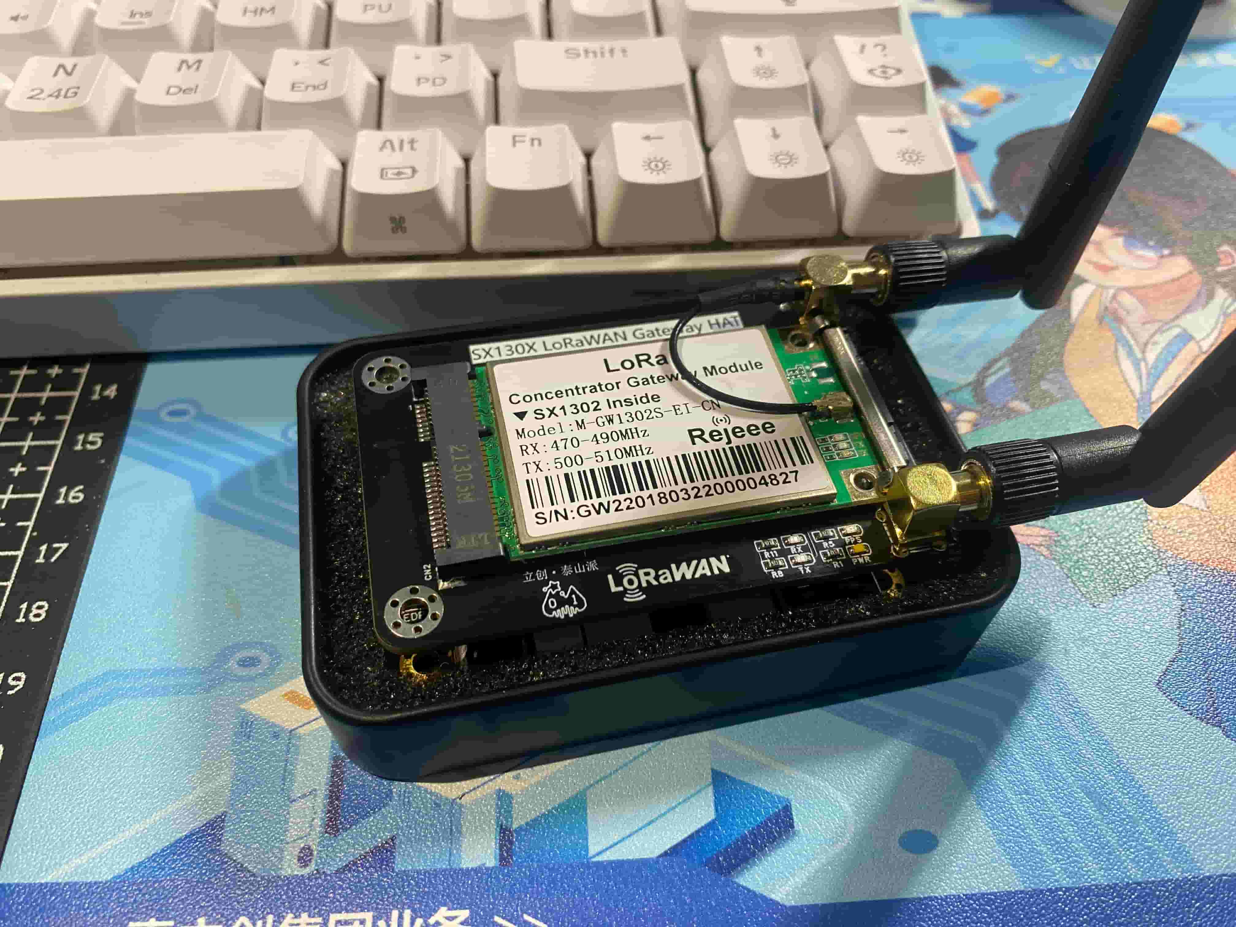
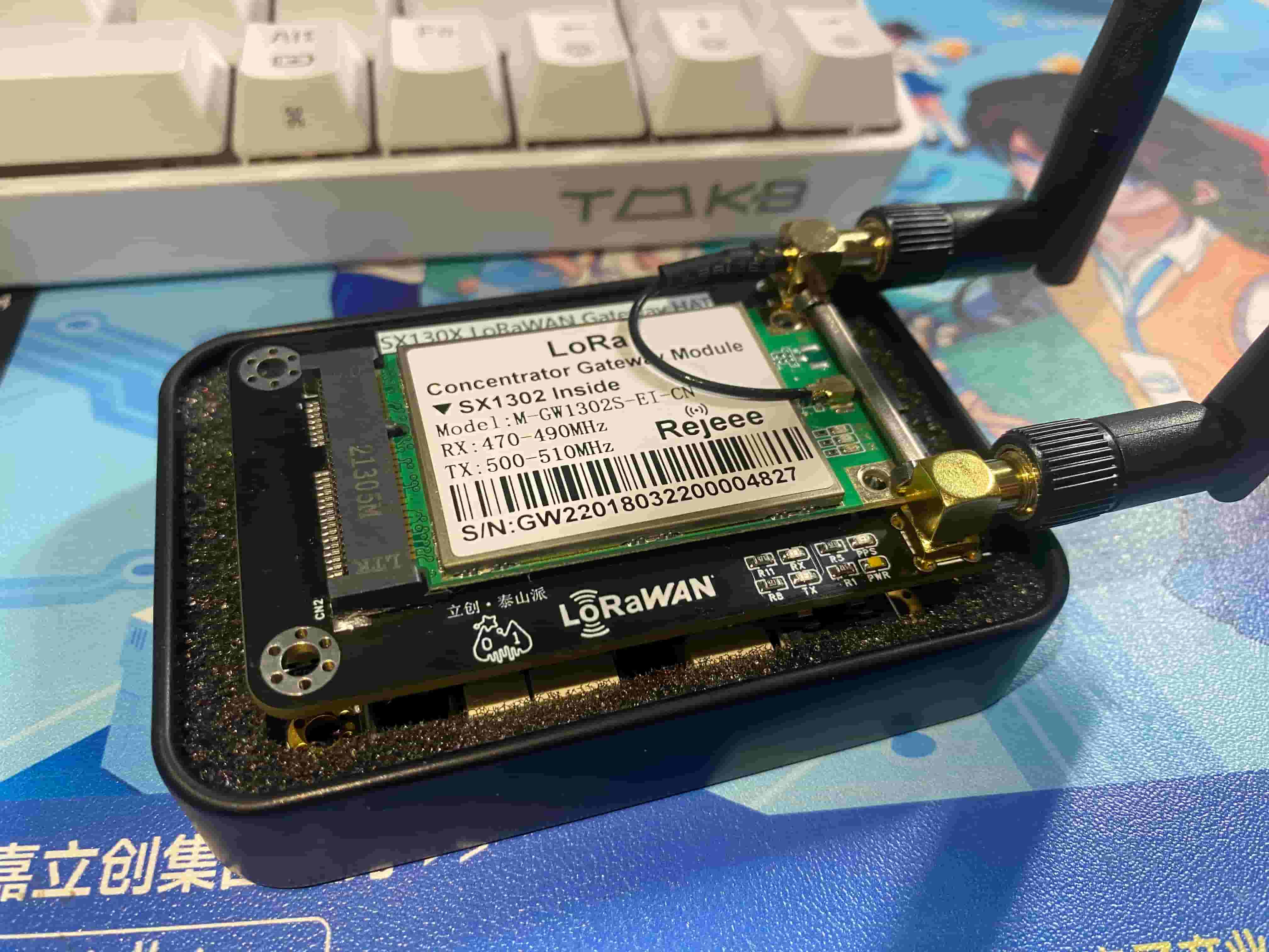
Taishanpai LoRaWAN Gateway Expansion Board SX1302
It is compatible with Taishanpai's LoRaWAN gateway expansion board, and adds GPS for location and message timestamps.
Project Log:
------Hardware Version: V1.1 Software Version: V1.0 Log------
1. Modified the order of expansion interfaces
2. Modified the order of logo silkscreen printing
3. Modified the DC-DC circuit layout.
Data has been uploaded as an attachment. Please leave a message at the bottom if you have any questions.
Video Address:
Project Introduction:
This project is a LoRaWAN expansion board based on the Taishanpai development board. Installing this board can instantly turn Taishanpai into a LoRaWAN gateway server.
This solution has lower manufacturing and cost compared to other LoRaWAN development boards, and is easy to manufacture.
If you like it, you are welcome to replicate it and make progress together, building the Taishanpai ecosystem.
Project Functions:
Onboard red LED indicator for power supply indication
. Uses the Hezhou AIR530Z GPS module. Compact, powerful, and easy to use.
Onboard three indicator lights for displaying GPS status (transmitting and receiving PPS signals).
Built-in GPS hot-start circuit. Uses a 3V rechargeable battery.
Uses the M-GW-SX1302S-EI-CN SPI LoRaWAN module from Jiangsu Ruijie Intelligent Technology Co., Ltd.
Powered by a Silergy SY8089 DC-DC power supply.
An SMA antenna mount is used for signal reception and transmission, and various antenna styles and lengths can be connected.
Instructions for use:
The project is still under testing; successful testing will be uploaded as an attachment.
Physical demonstration:

Precautions:
1. When soldering, please pay attention to the soldering order to ensure correct power supply and avoid burning out subsequent circuits!
2. The soldering order should follow the principle of from shortest to smallest, and from inside to outside.
3. Data calibration should be performed according to the steps in the official manual; select the appropriate NTC resistor according to your needs.
PDF_Taishanpai LoRaWAN Gateway Expansion Board SX1302.zip
Altium_Taishanpai·LoRaWAN Gateway Expansion Board SX1302.zip
PADS_Taishanpai LoRaWAN Gateway Expansion Board SX1302.zip
BOM_Taishanpai LoRaWAN Gateway Expansion Board SX1302.xlsx
94536
PMDG737-MPU peripherals developed based on SimConnect
The PMDG737-MCP is based on SimConnect and
has only been tested in MFS2020 so far.
The power input directly provides 5V to the MAX7219 and 3.3V to the AT24C02, CH340, and STM32F103C6T6 via the 1117. Considering the potentially high power consumption of the digital tube, a power supply connection is reserved.
The main control

digital tube display uses a digital tube driver chip, which effectively reduces I/O usage.
Buttons are acquired using an ADC, achieving the effect of one I/O for multiple buttons. In practice, it can connect eight buttons and
three rotary encoders. However, most purchased rotary encoders already have buttons, which is an oversight and can be modified.

The AT24C02 is not very useful and can be left unsoldered. Its initial purpose was to store the digital tube brightness, but this is not yet implemented in the program.

The CH340 communicates with the PC, and
LEDs are used for indication. See the

program documentation: https://gitee.com/gu2188/PMDG737-MPU-PC_microcontroller_program
, https://gitee.com/gu2188/PDMG737-STM32_demonstration_video
, and https://www.bilibili.com/video/BV1JU411d7mi
PDF_PMDG737-MPU Peripherals Based on SimConnect.zip
Altium_PMDG737-MPU peripherals developed based on SimConnect.zip
PADS_PMDG737-MPU peripherals developed based on SimConnect.zip
BOM_PMDG737-MPU Peripherals Based on SimConnect.xlsx
94537
electronic


 京公网安备 11010802033920号

 P8395-90


