


 Design Process Record:
  testing of AD9910 module waveform output function.
 Overall System Construction and Function Verification:
  During this period, the system baseboard was designed, located in the function file directory -- project name: Baseboard PCB.

 and assembling the baseboard is the basic process, which will not be elaborated here, as this is a basic skill for electronic engineers.
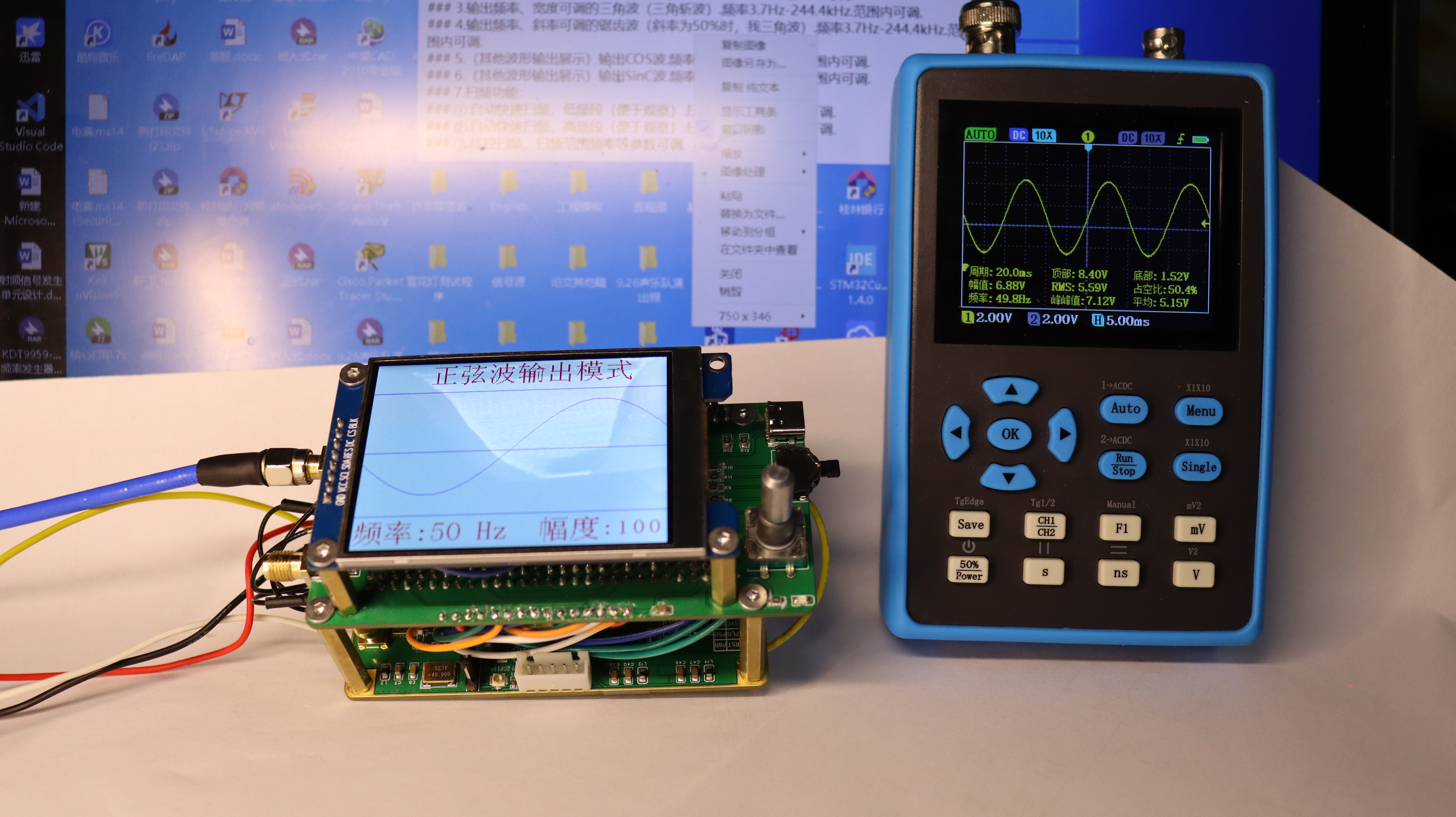
  Operation Instructions: The frequency of the sine wave can be adjusted in this interface, with a minimum adjustment step of 1Hz. The waveform amplitude can also be adjusted in this interface, with a maximum amplitude of full-scale output, approximately 700mVpp.
 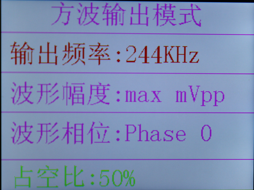 Operation Instructions: The frequency and duty cycle can be adjusted in this interface, with a maximum frequency of 244kHz and a minimum of 3.7Hz. The step size is related to the register data; please refer to the datasheet for details. The example shown is a 16-step value. The square wave waveform has a duty cycle step frequency of 10%, with a maximum of 90% and a minimum of 10%.
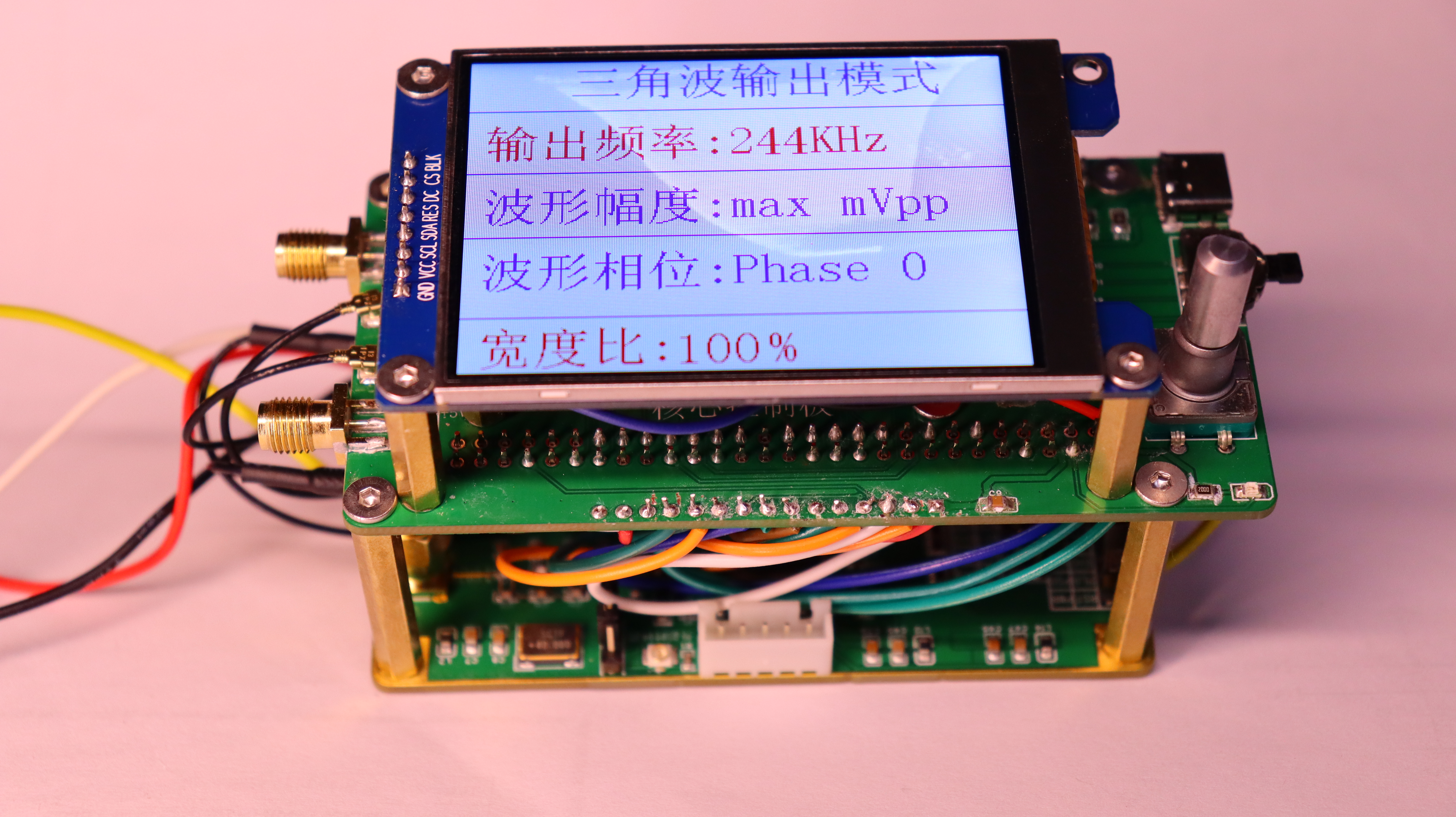
 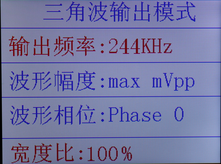 Operation instructions: In this interface, the frequency and width ratio of the waveform can be adjusted. The frequency range is the same as that of the square wave. The width ratio of the triangle wave is 10%-100%, with a step of 10%.
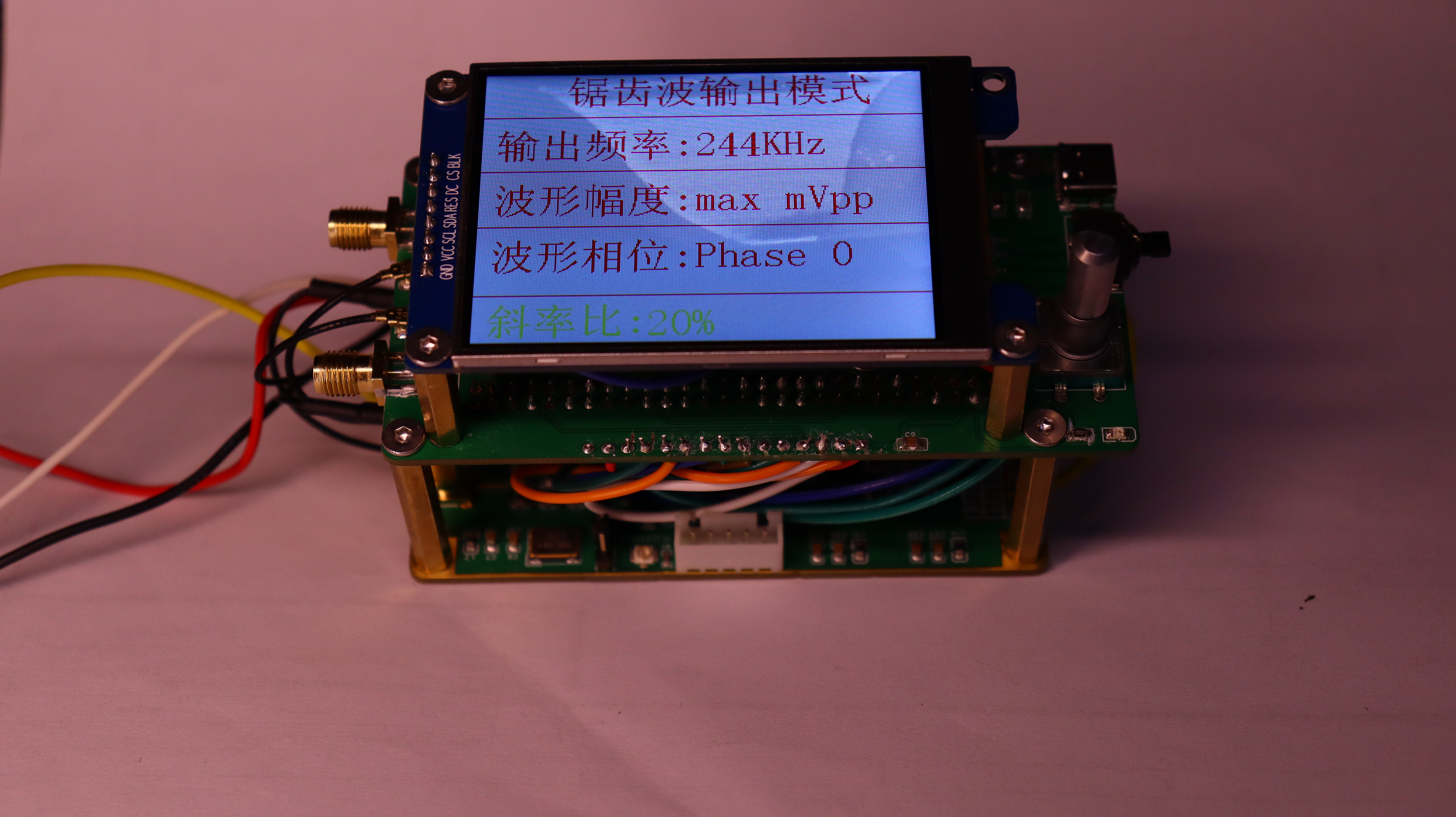
  Operation instructions: In this interface, the frequency is adjusted in the same way as the square wave and sine wave. The slope ratio of the waveform can be adjusted, with an adjustment range of 10%-100%, and a step of 10%. When the slope ratio is 50%, the waveform is the same as that of the triangle wave when the width ratio is 100%.
 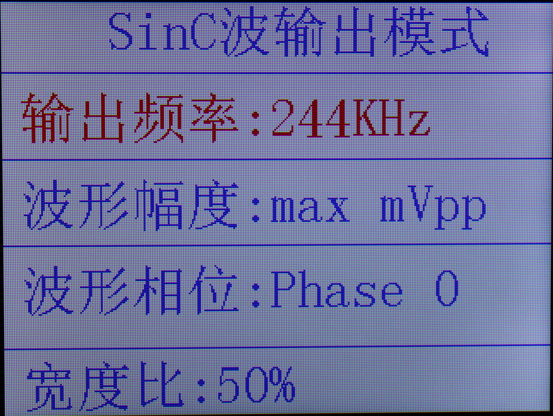 Operation instructions: In this interface, the frequency of the waveform can be adjusted. The frequency range is the same as that of the waveform described above.
 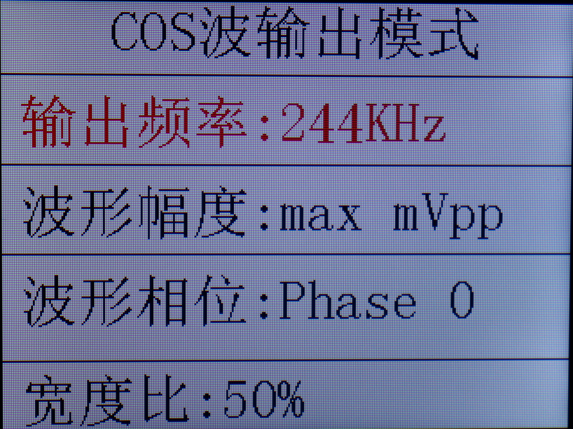 Operation instructions: The waveform frequency can be adjusted in this interface; the frequency range is the same as the waveform frequency described above.
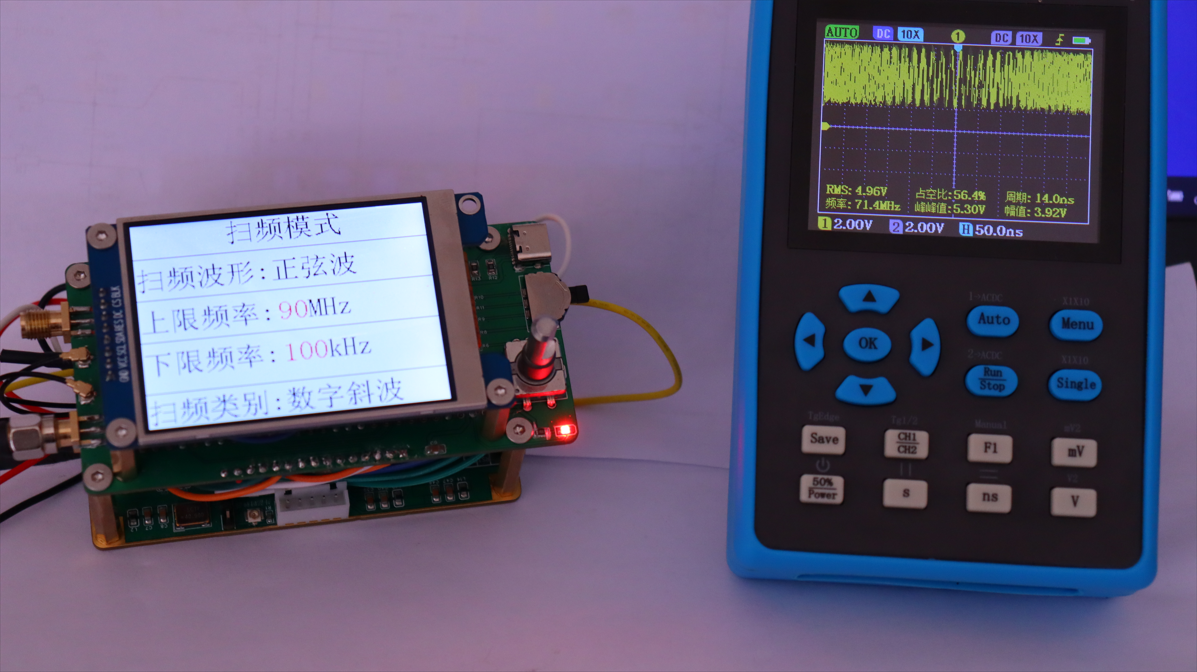
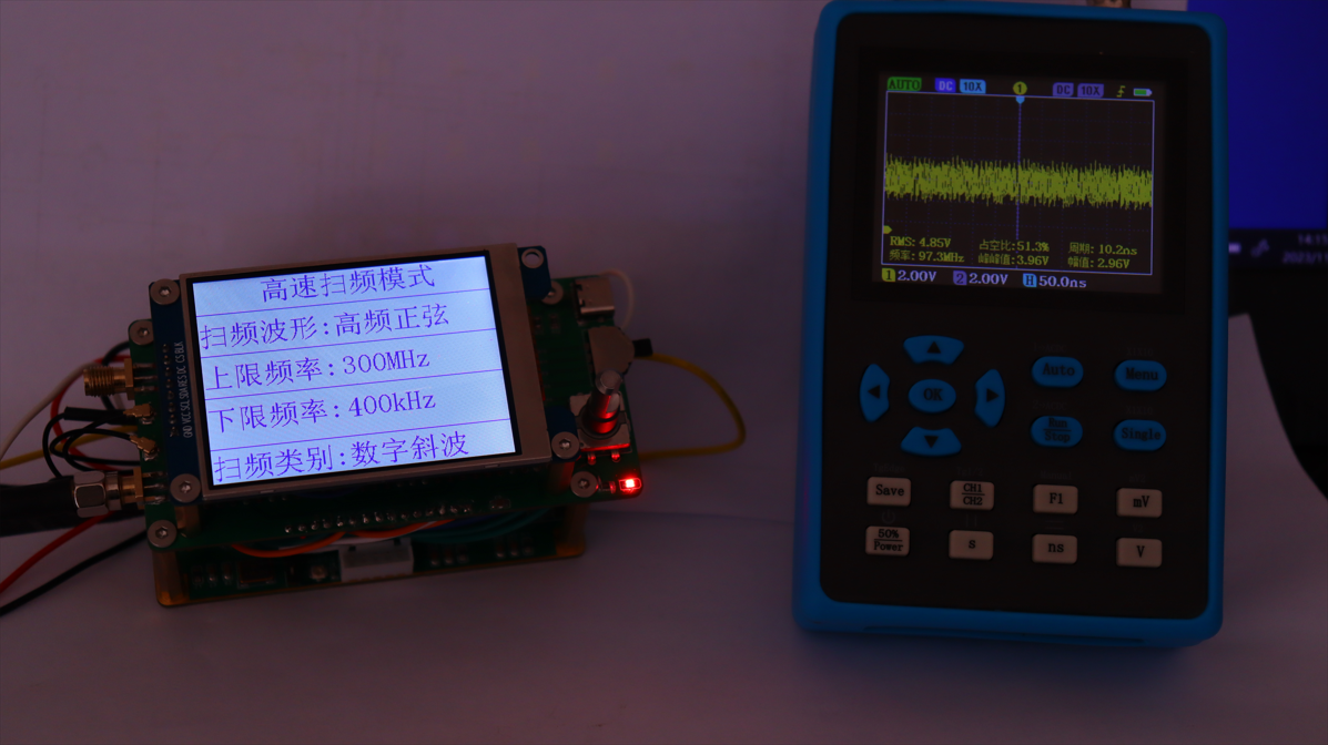
 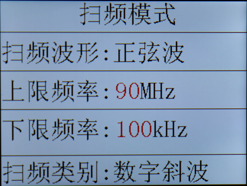 Operation instructions: In this mode, the upper and lower limit frequencies of the waveform can be adjusted; the frequency range is 1Hz-420MHz.
 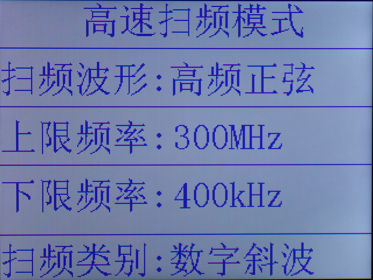 This mode only displays the frequency sweep waveform; the adjustable frequency sweep range is not shown. (The oscilloscope is terrible, the waveform is unclear even after scanning!).
 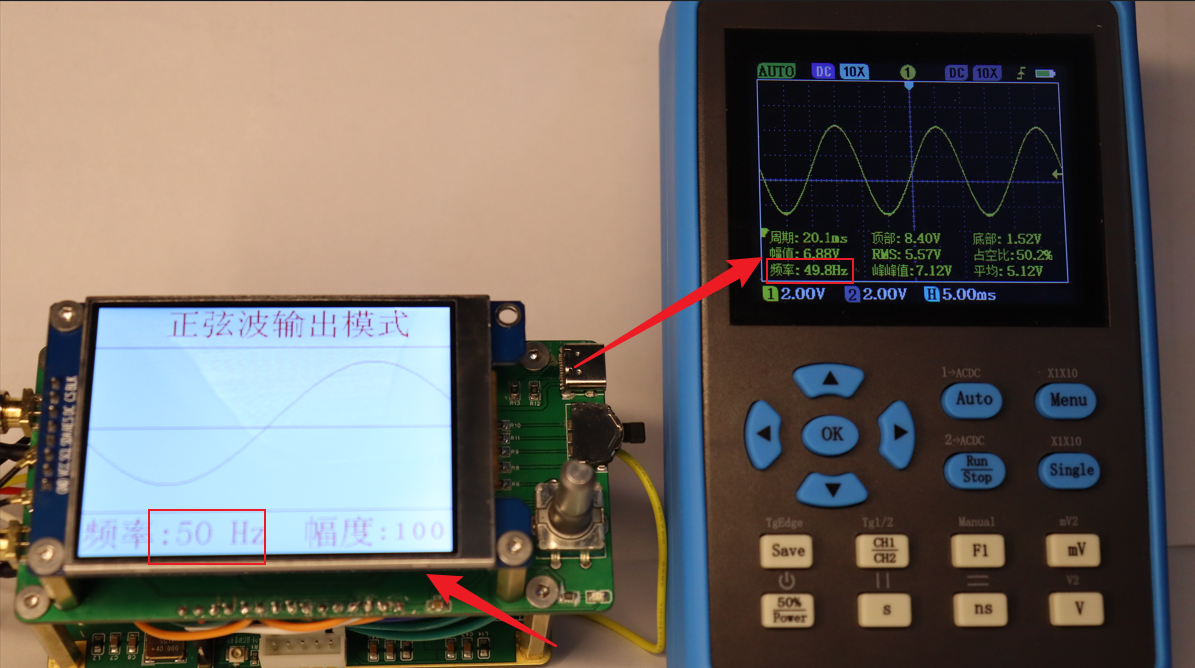 2. 136Hz waveform, amplitude 100% output.
  3. 203Hz waveform, amplitude 54% output.
  4. 363Hz waveform, amplitude 75% output.
  5. 502Hz waveform, amplitude 91% output.
 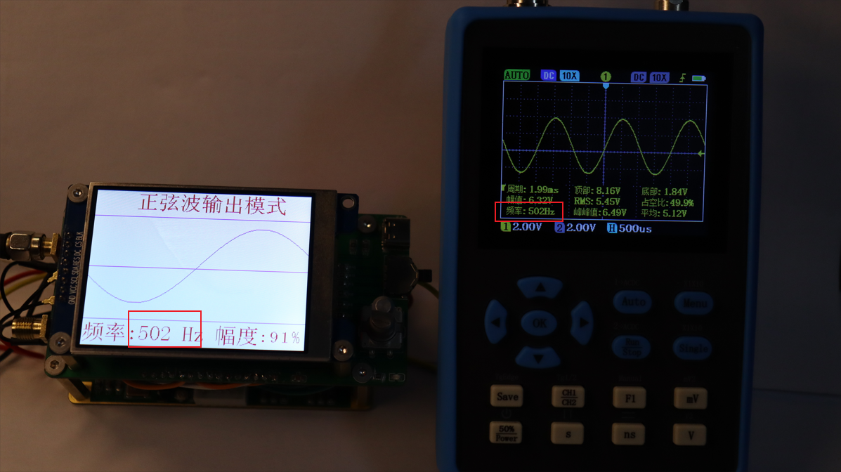 This shows that within the Hz range, the waveform parameters and output parameters are consistent.
 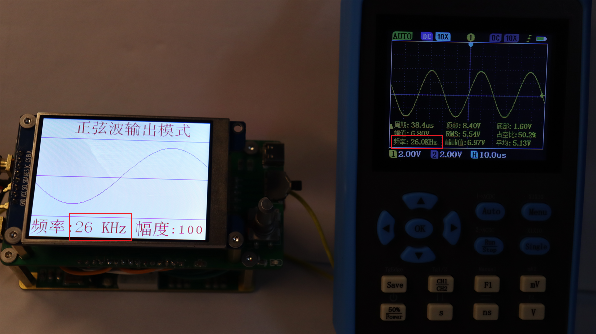 2. 53kHz waveform, amplitude 55% output.
  3. 145kHz waveform, amplitude 71% output.
 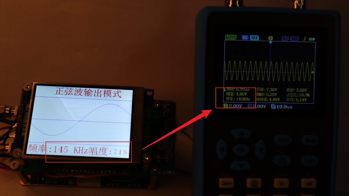 4. 220kHz waveform, amplitude 51% output.
  5. 369kHz waveform, amplitude 66% output.
 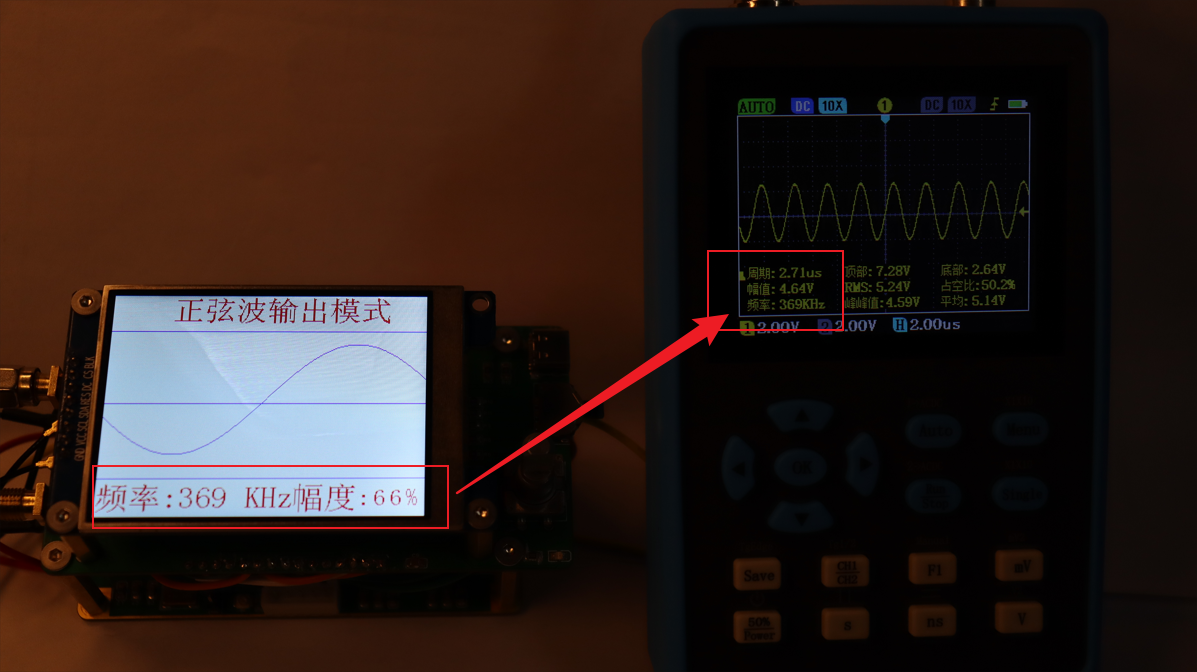 6. 593kHz waveform, amplitude 100% output.
  #Testing waveform output in the MHz range of a sine wave:
  2. 16MHz waveform, 77% amplitude output.
 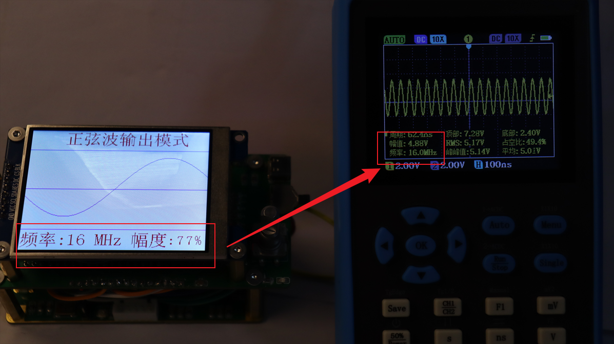 3. 39MHz waveform, 77
 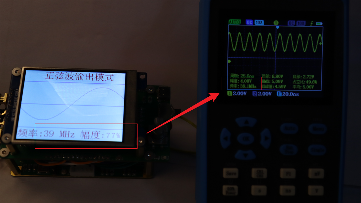 % amplitude output. 4. 81MHz waveform, 77% amplitude
  output. 5. 96MHz waveform, 77
 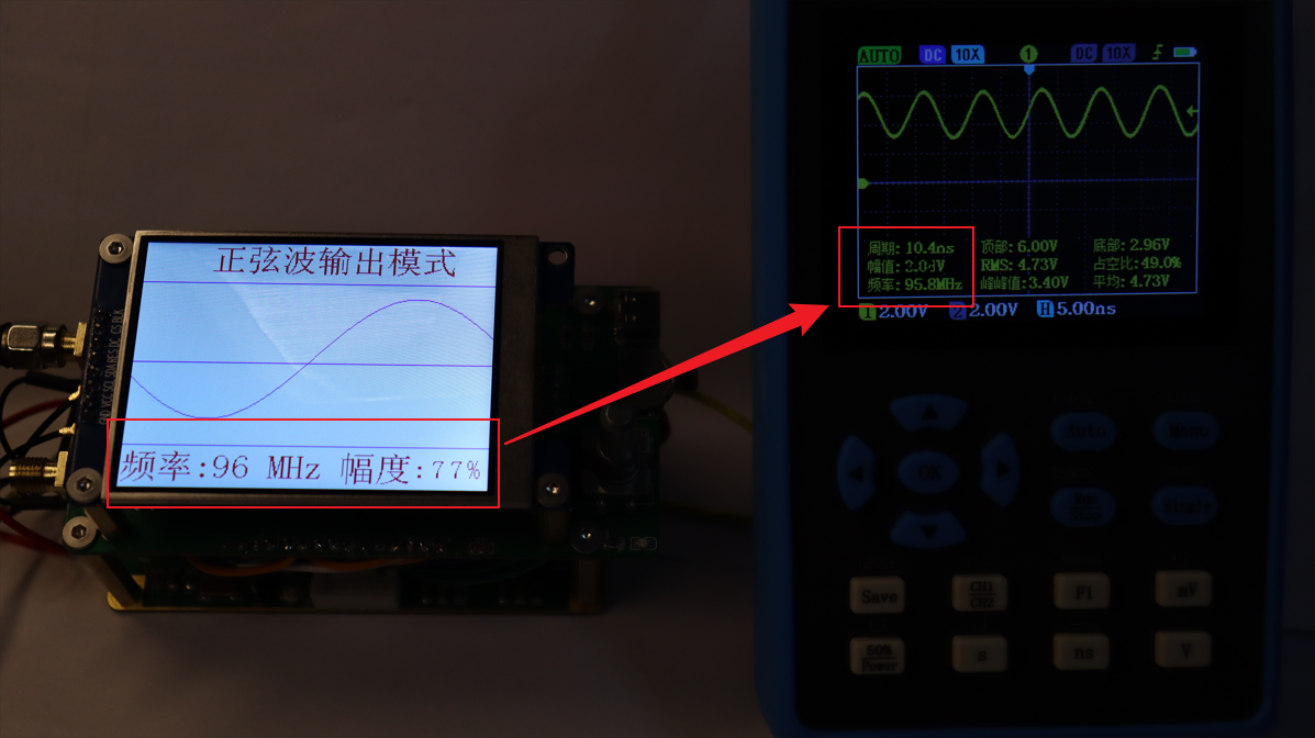 % amplitude output. 6. 95MHz waveform, 100% amplitude output.
 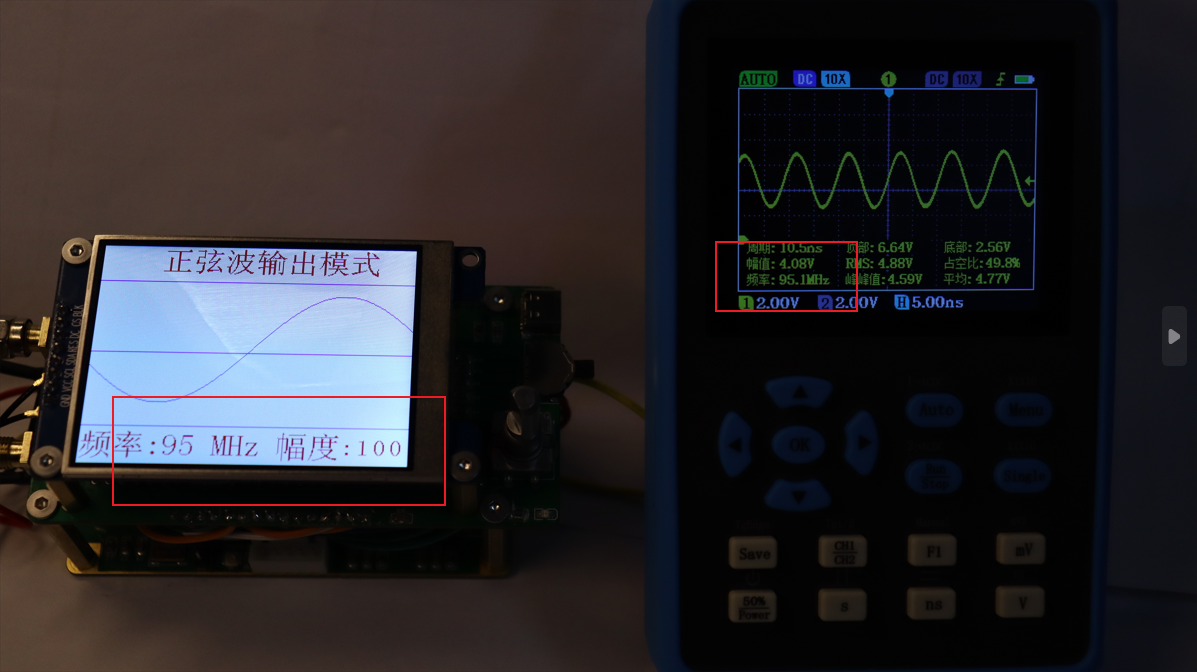 My oscilloscope can measure waveforms up to 100MHz without distortion, so frequencies above 100MHz cannot be tested. The AD9910 has a maximum output of 400MHz.
 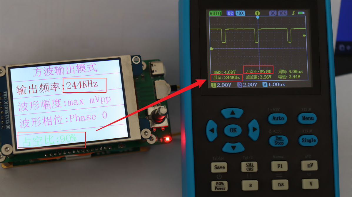 2. Output waveform with 90
  % duty cycle, frequency 122kHz. 3. Output waveform
 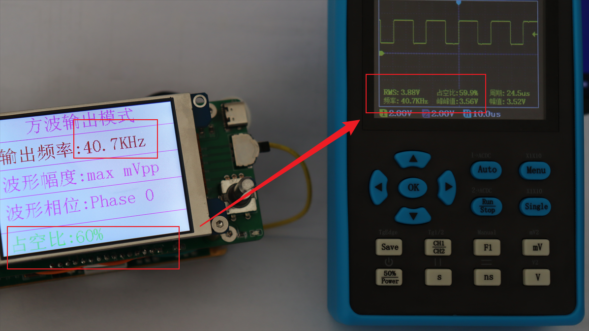 with 60% duty cycle, frequency 40.7kHz. 4.
  Output waveform with 60% duty cycle, frequency 34.9kHz. 5. Output waveform with 60% duty cycle, frequency 24.4kHz.
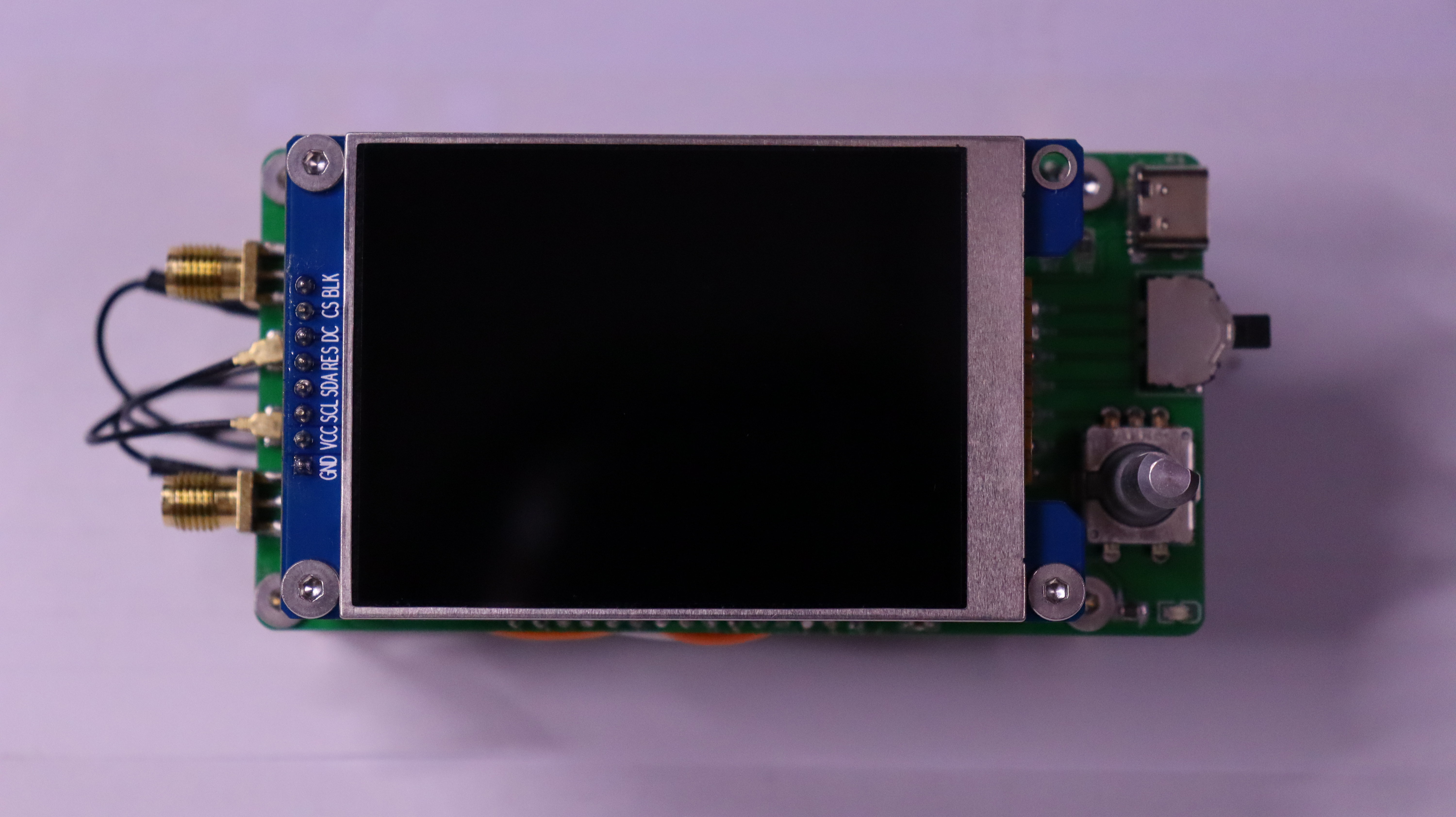
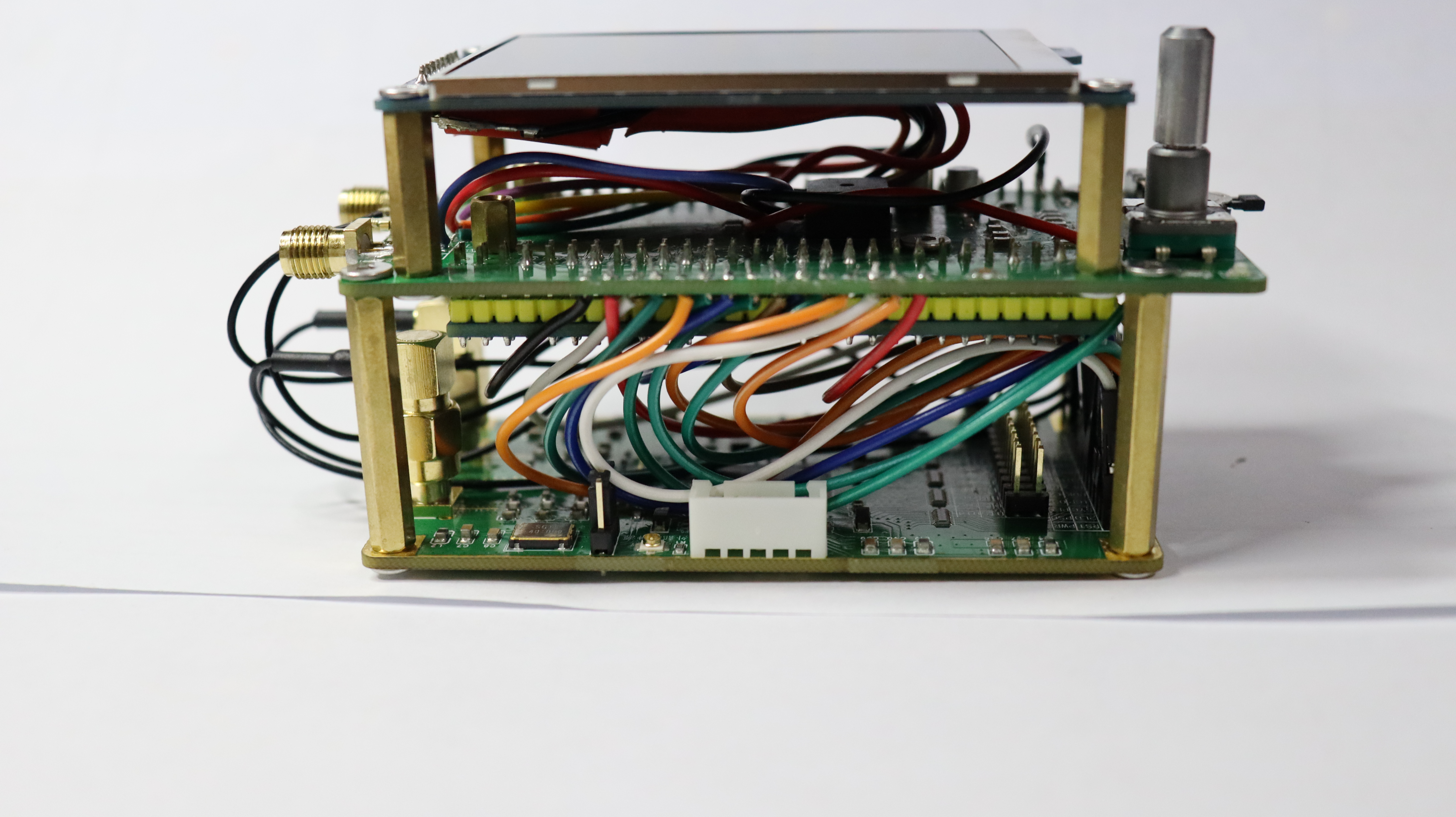
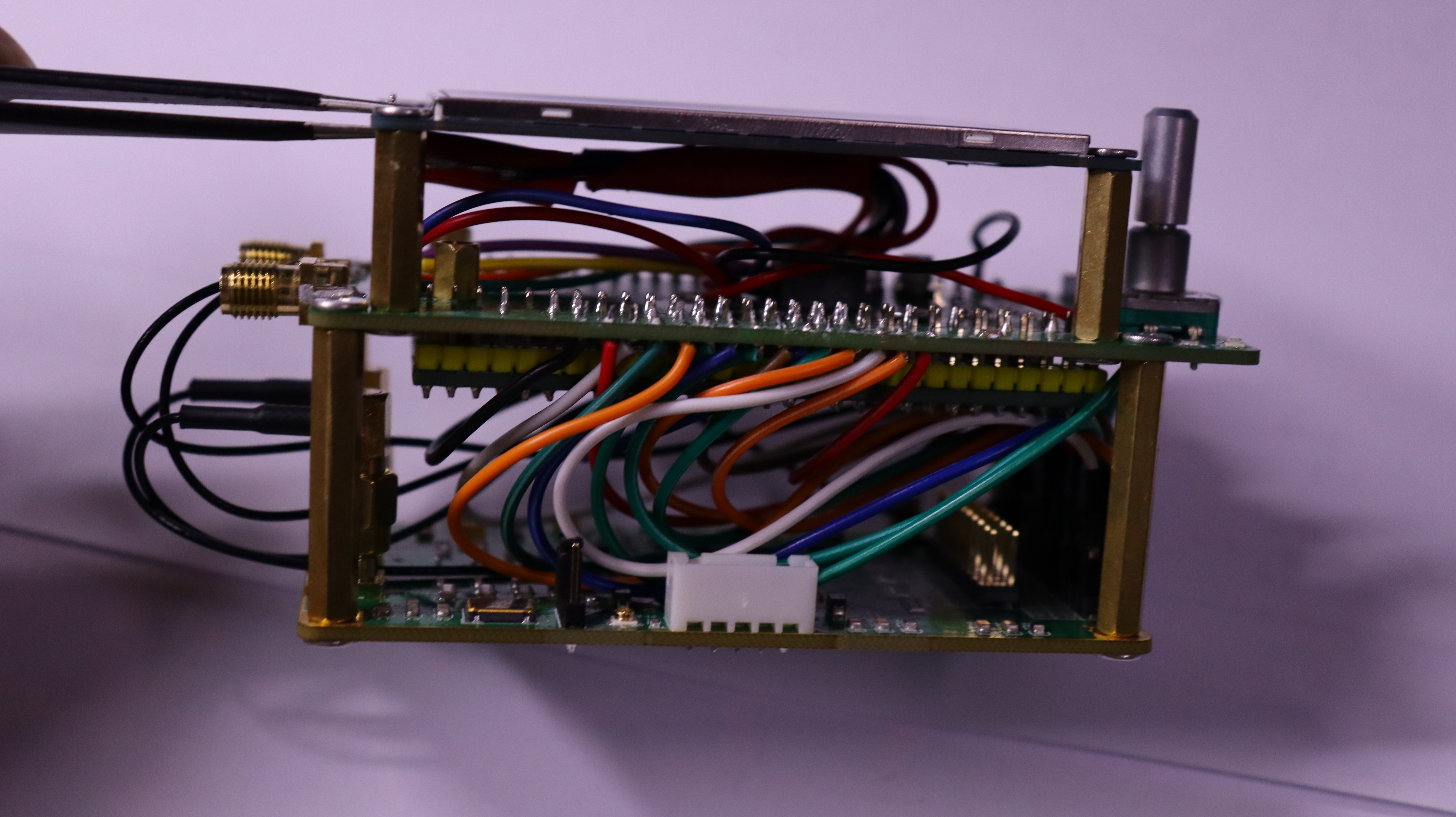
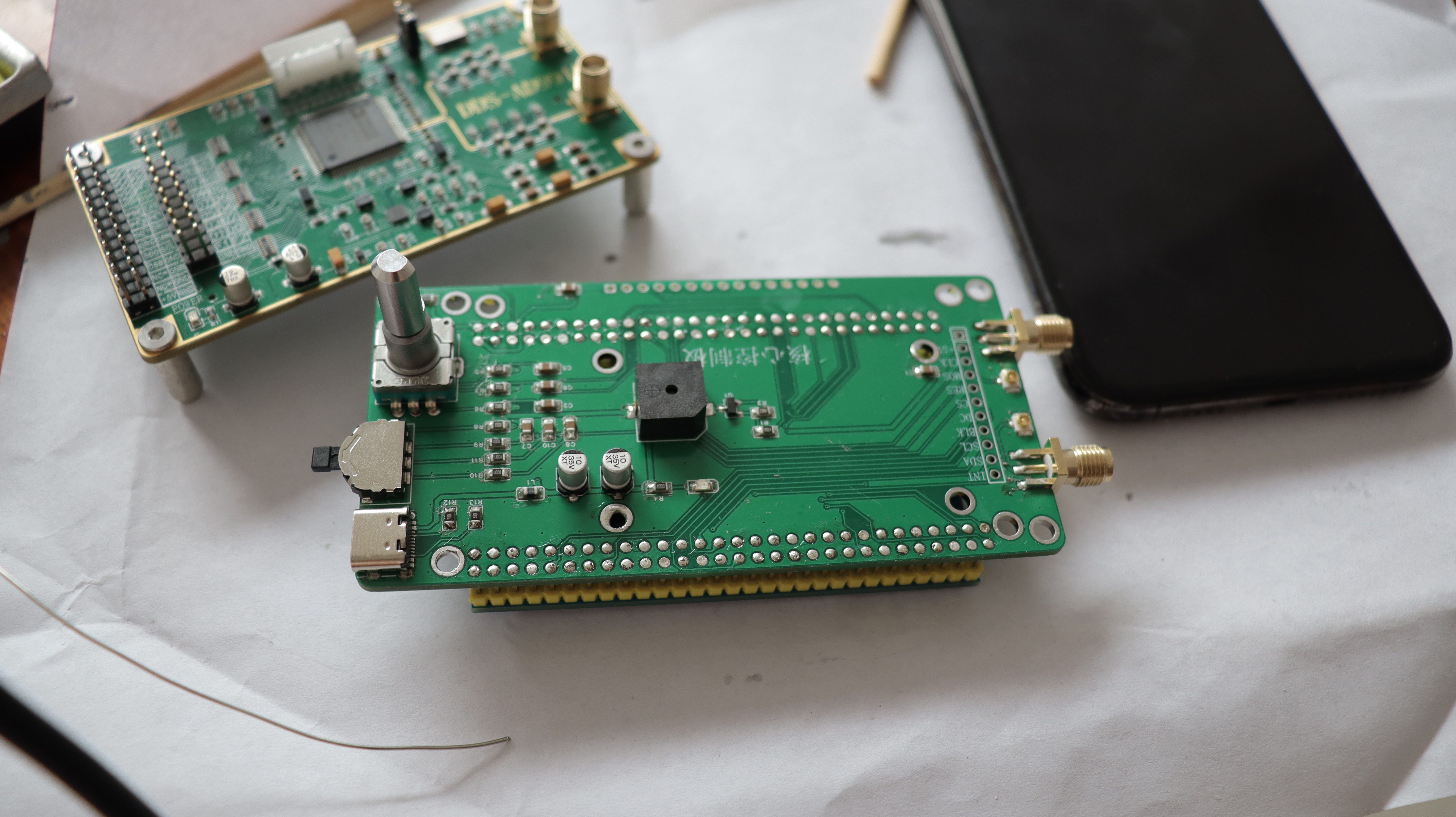
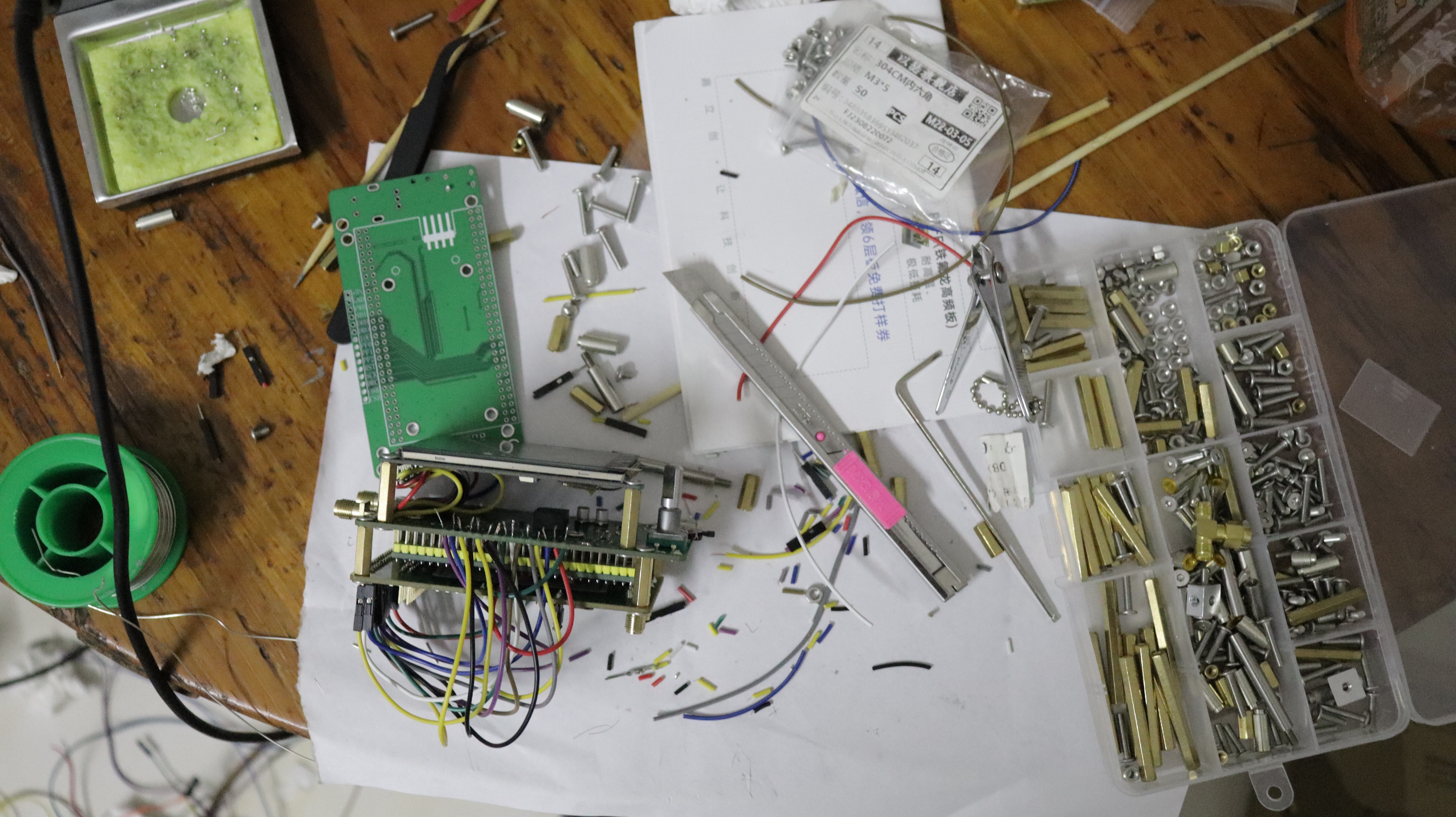
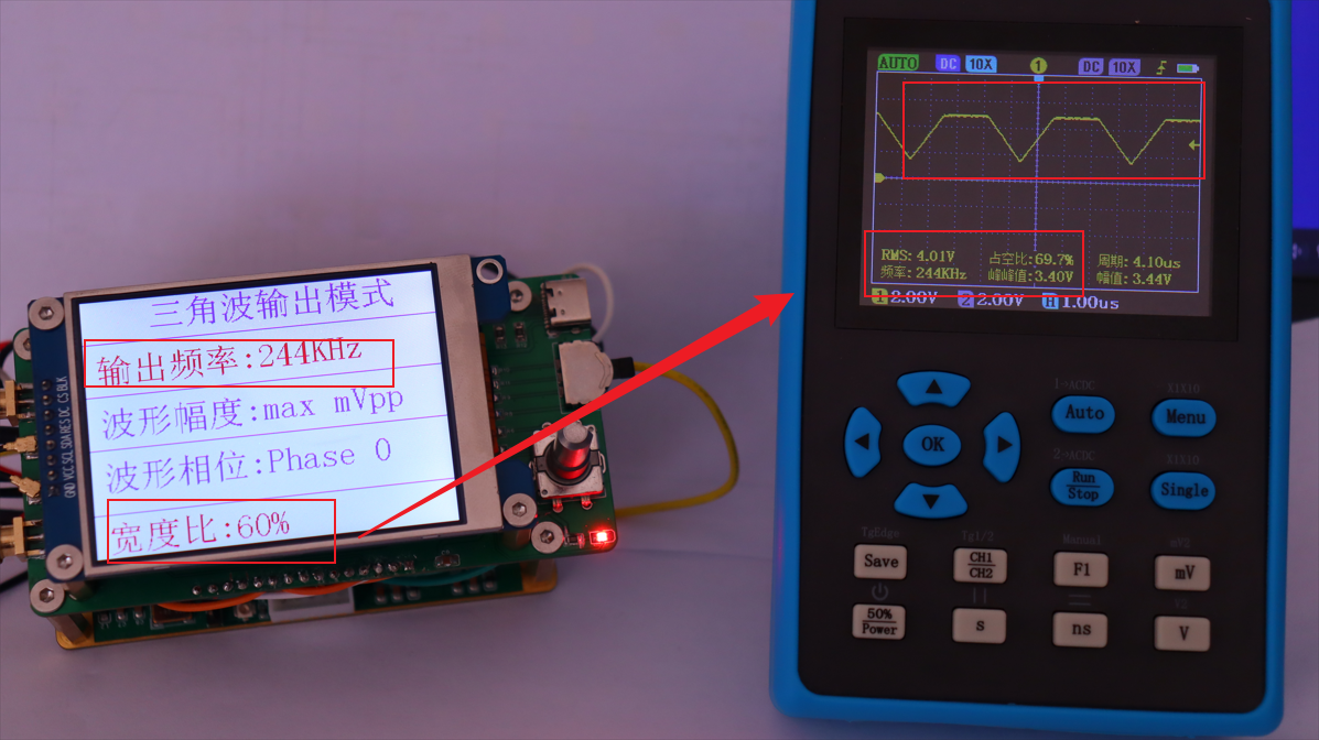
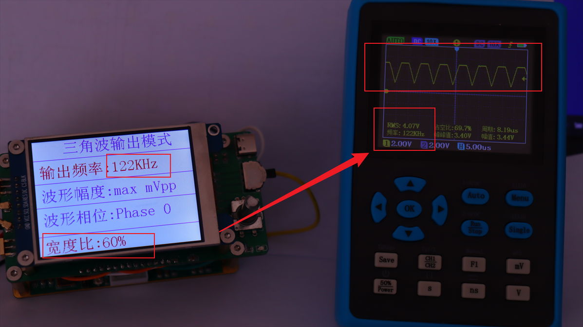
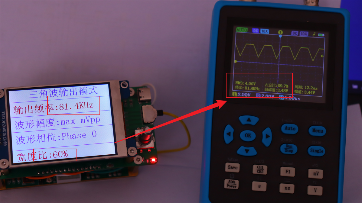
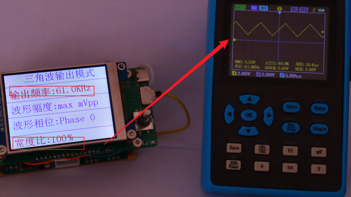
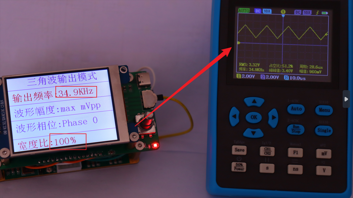
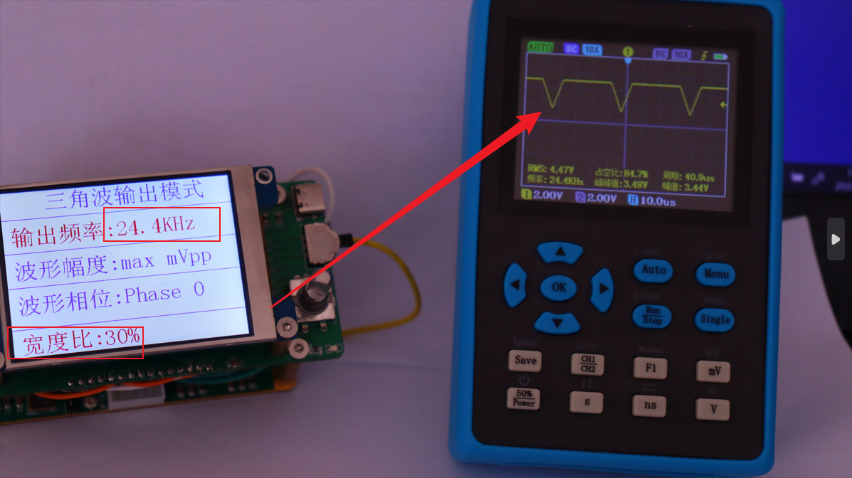
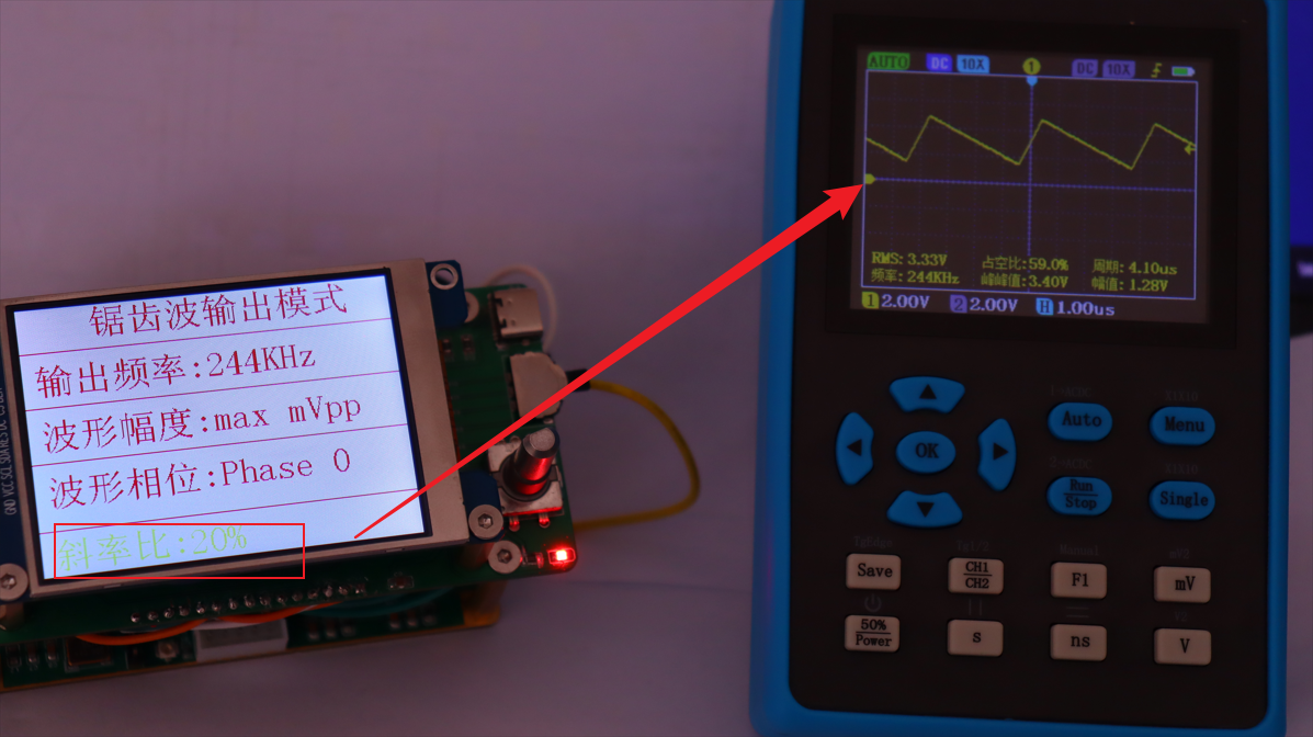
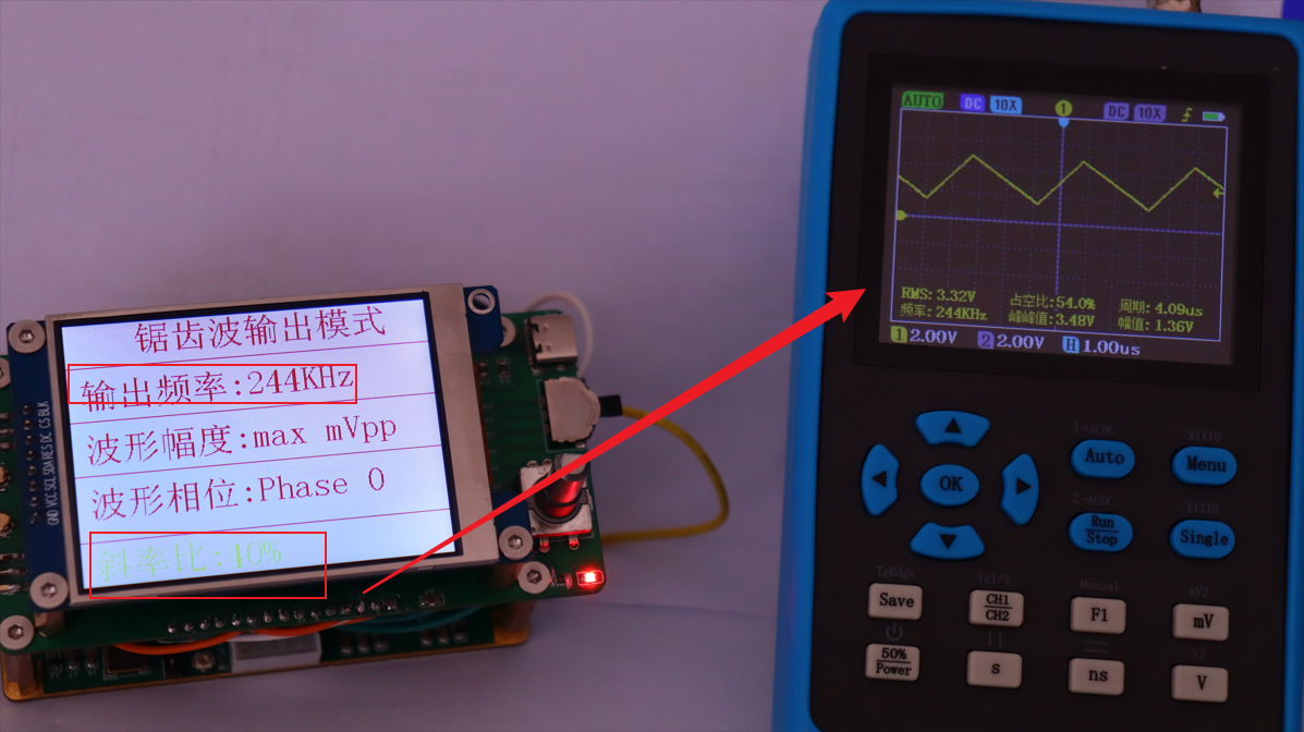
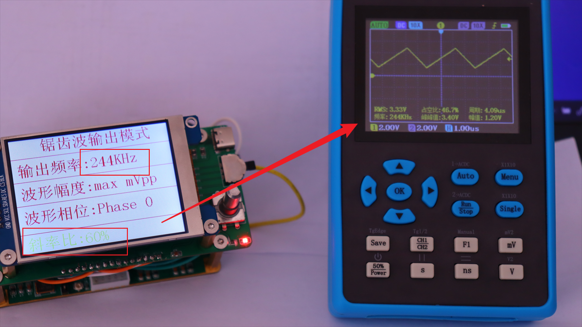
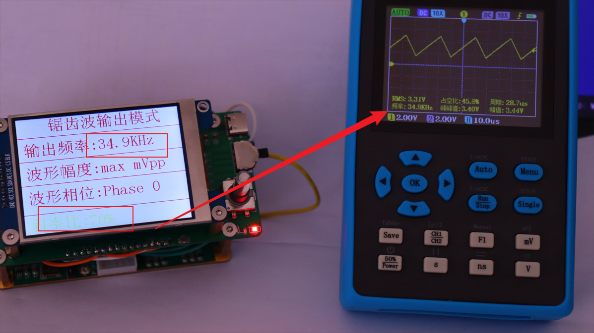
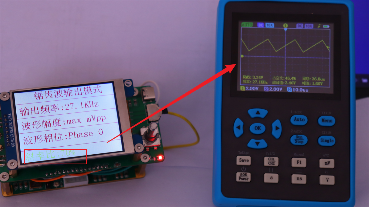
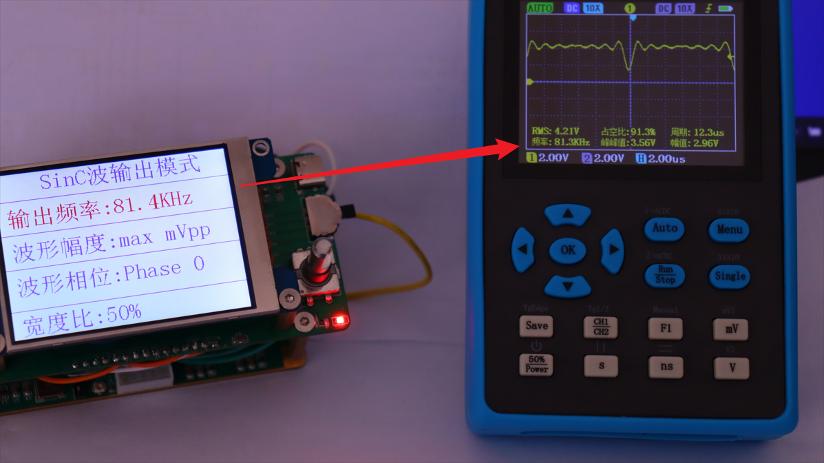
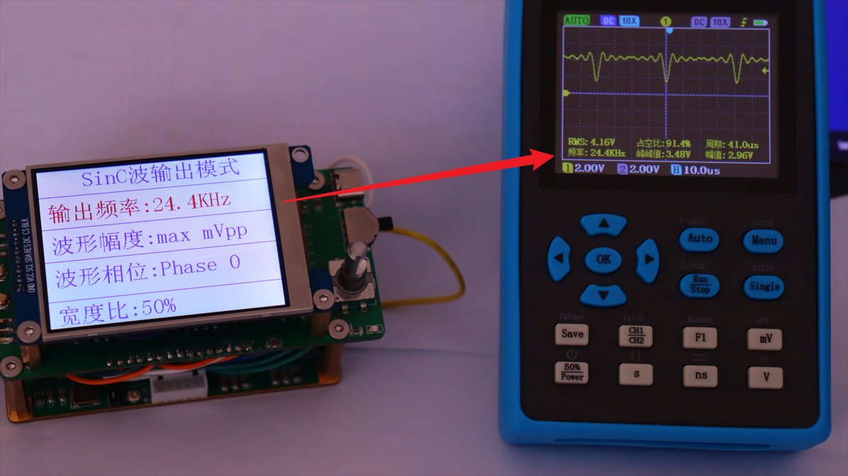
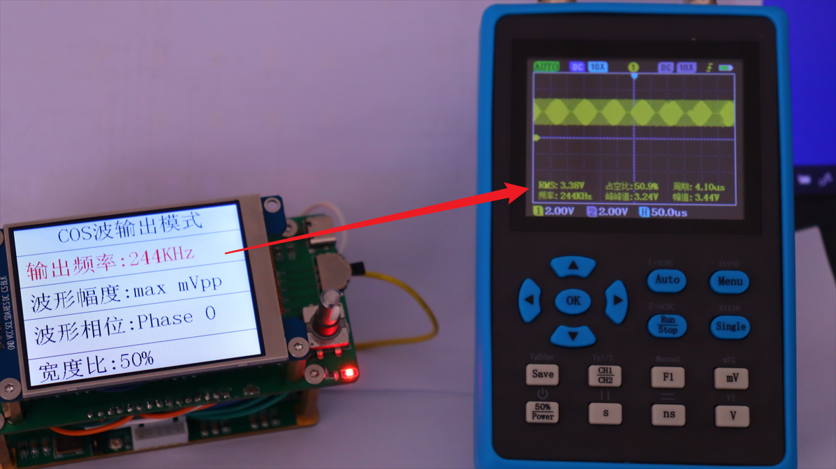
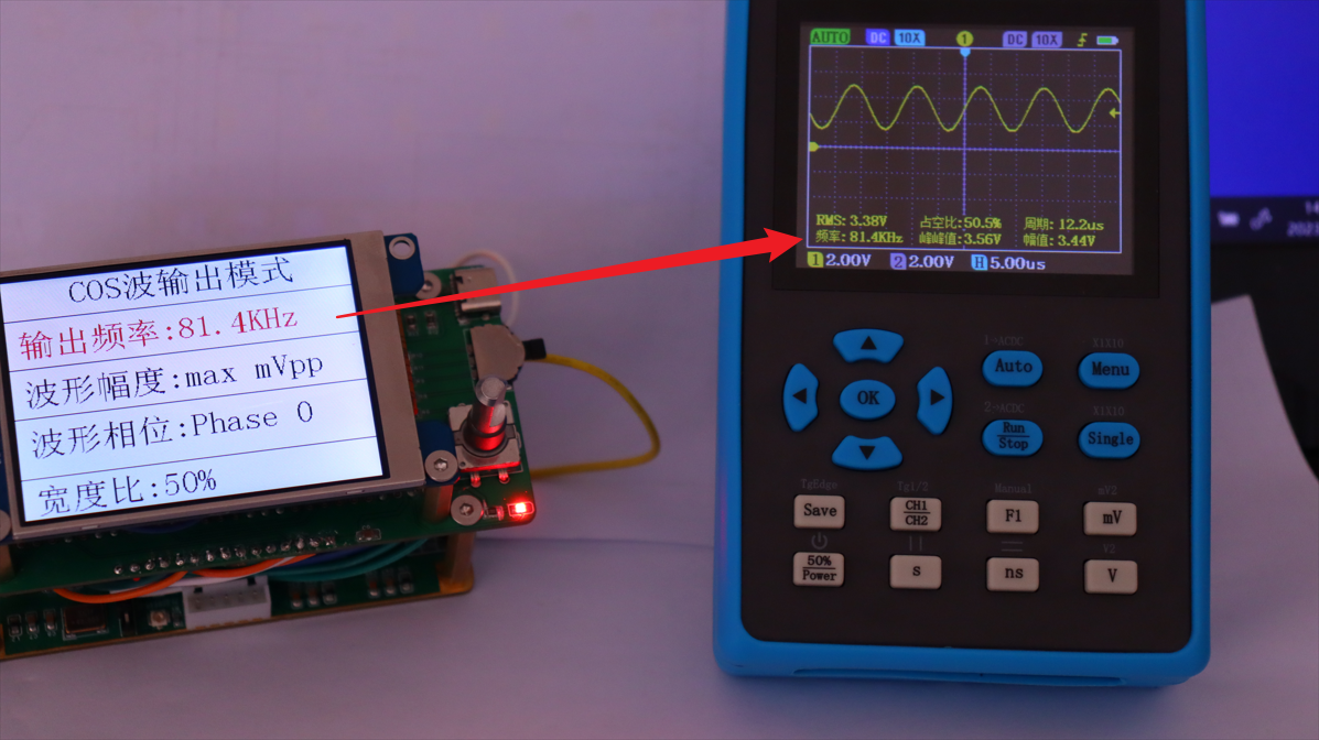
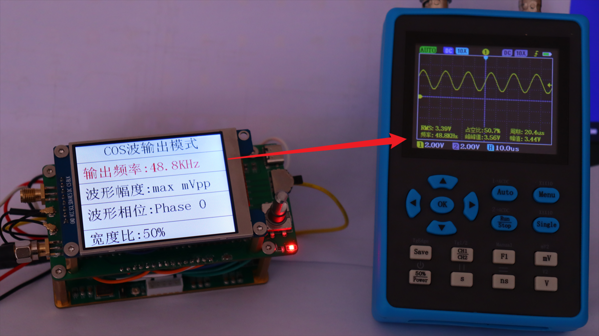
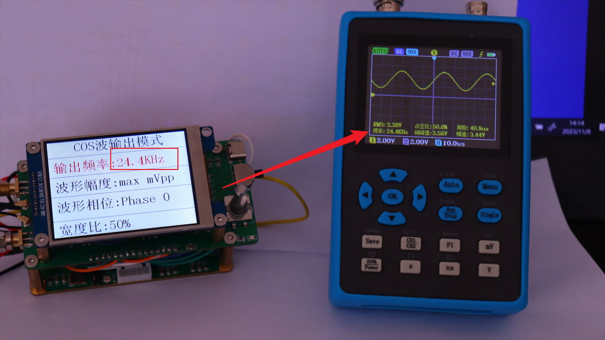
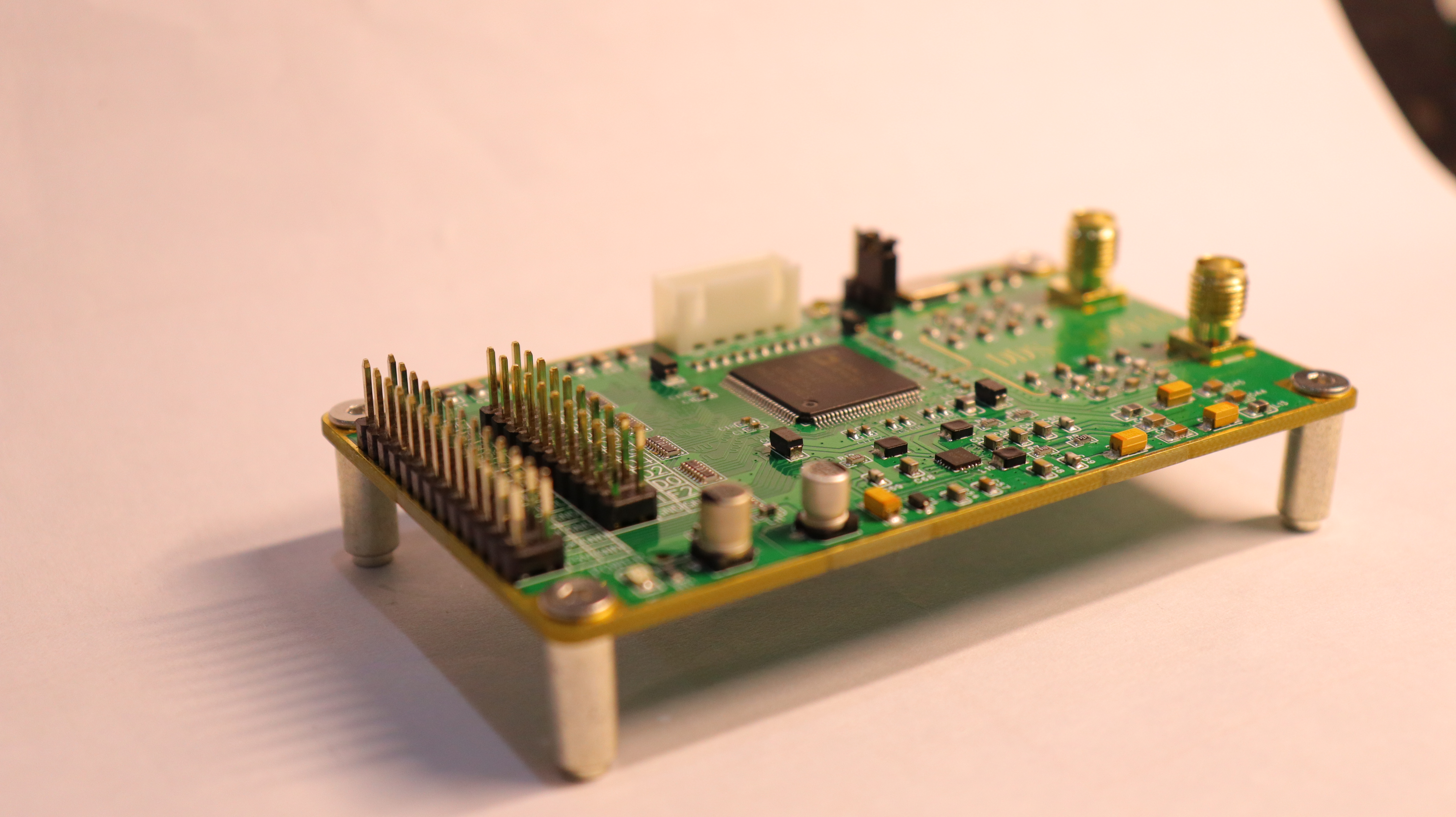
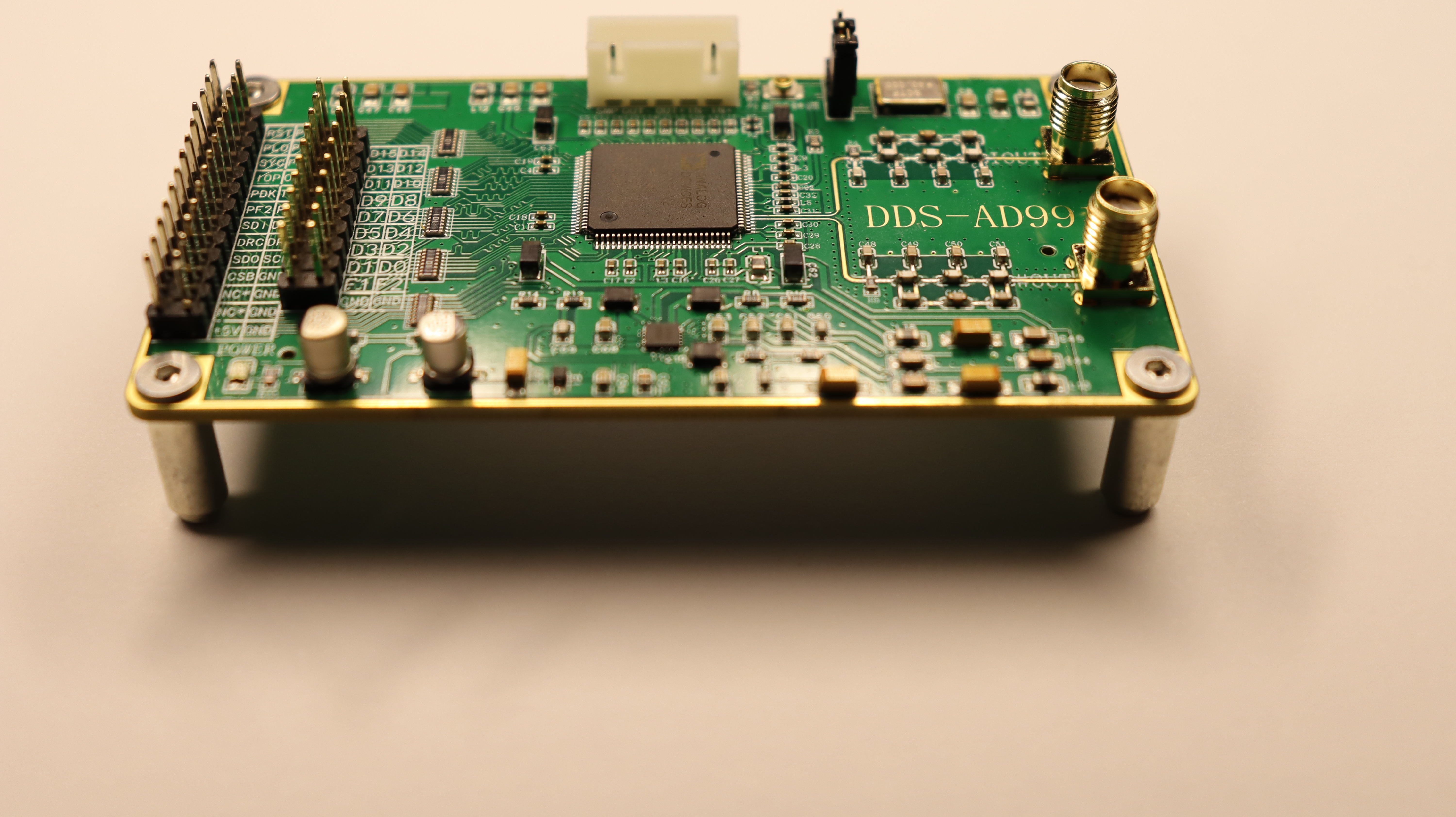
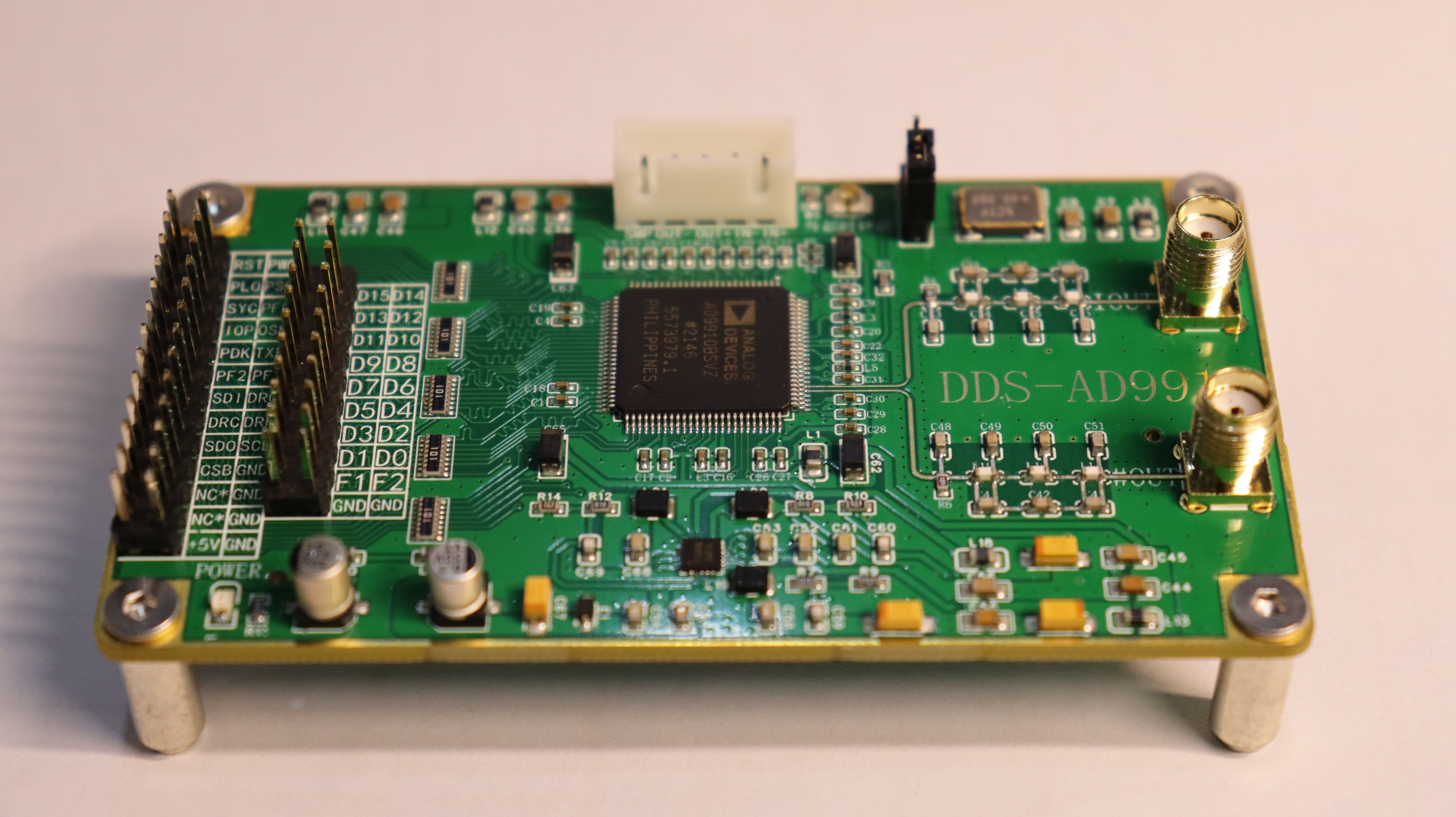
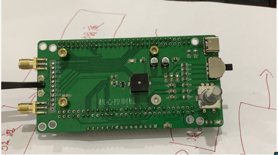
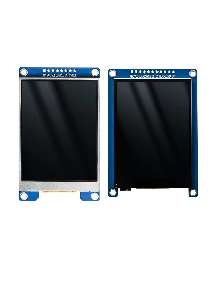
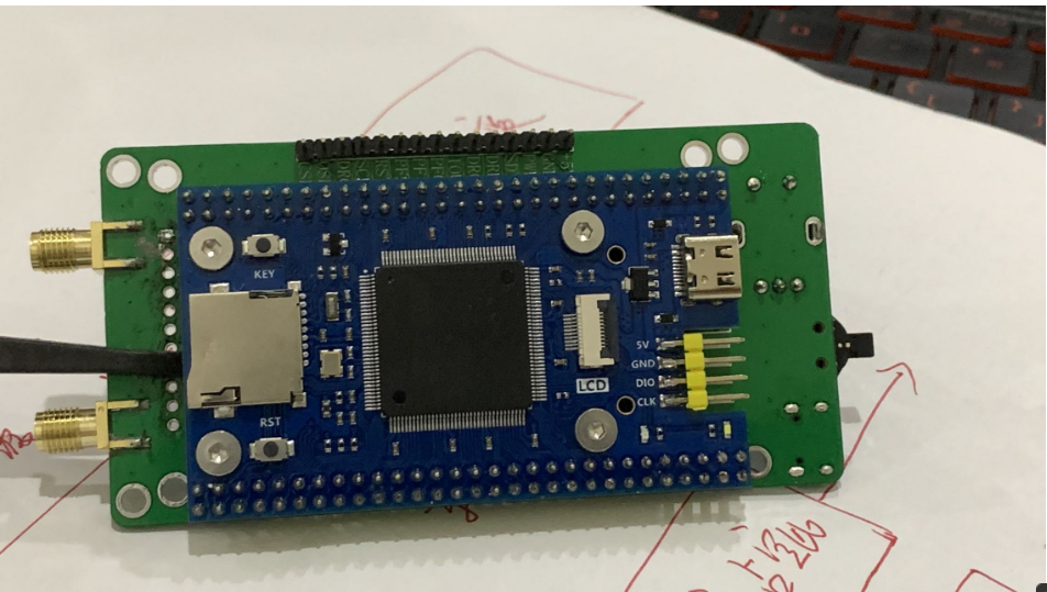
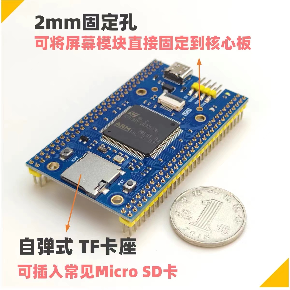
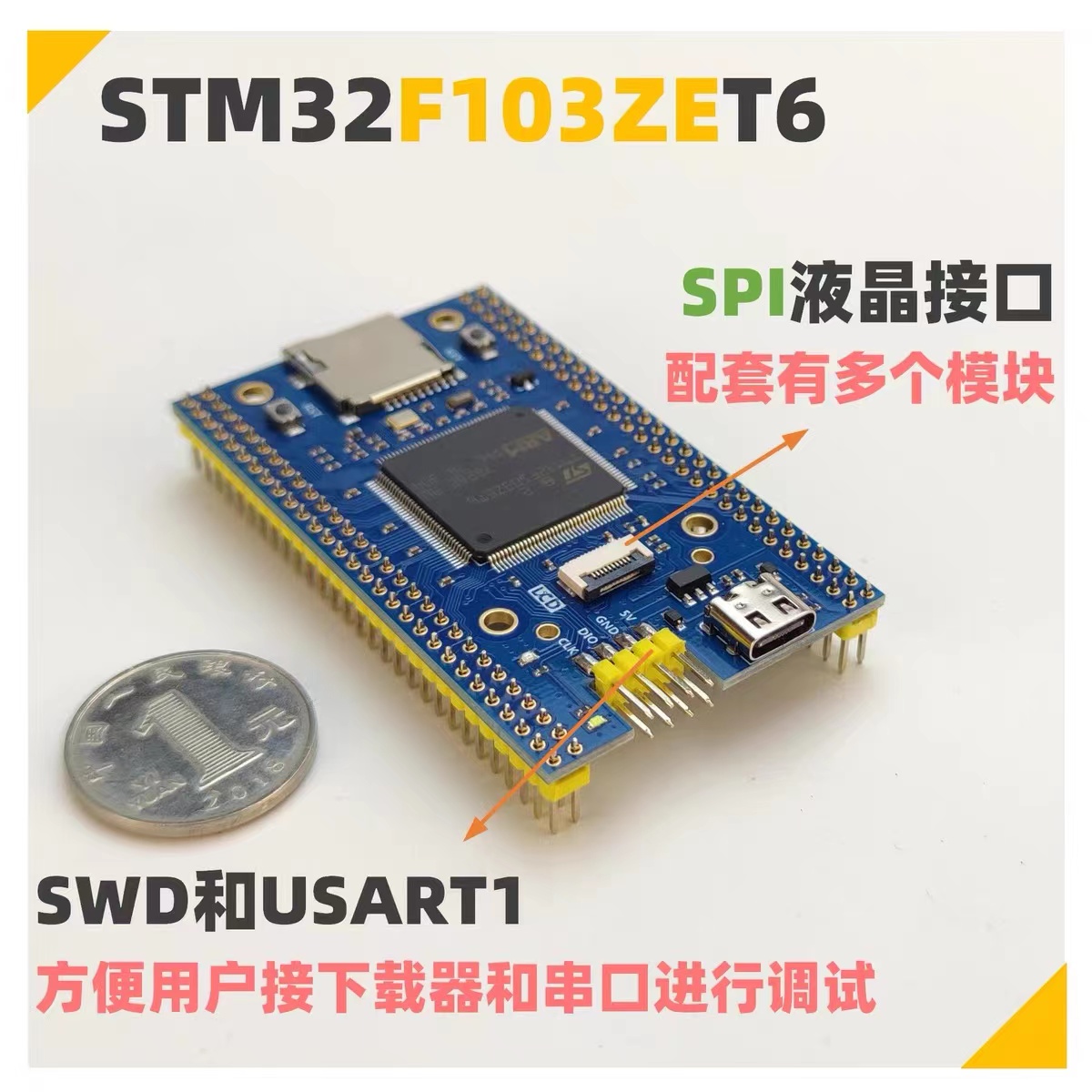
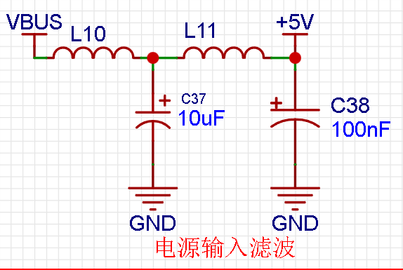
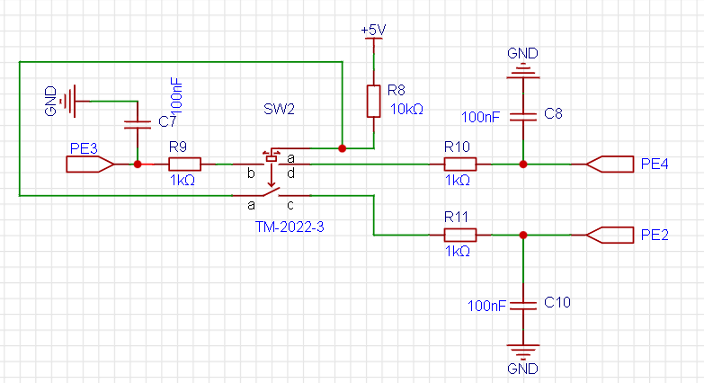
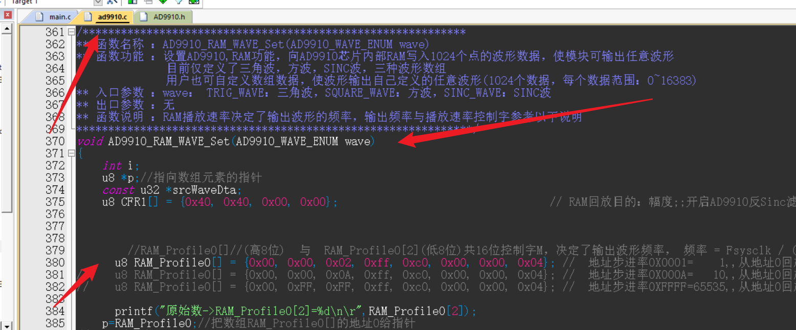
 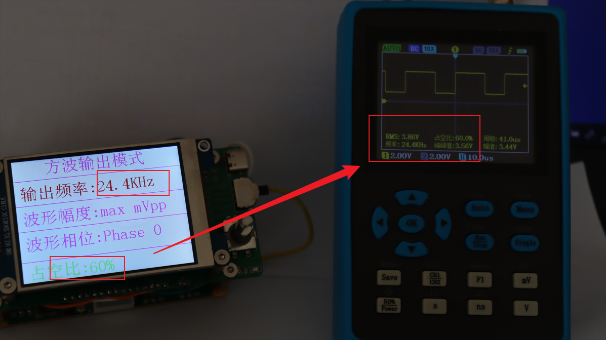 #Testing triangle wave waveform output (step width 10%): 1. Triangle wave output waveform with 100% width and a frequency of 244kHz. 2. Triangle wave output waveform with 60% width and a frequency of 244kHz. 3. Triangle wave output waveform with 60% width and a frequency of 122kHz. 4. Triangle wave output waveform with 60% width and a frequency of 81.4kHz. 5. Triangle wave output waveform with 100% width and a frequency of 81.4kHz. 6. Triangle wave output waveform with 100% width and a frequency of 61.0kHz. 7. Triangle wave output waveform with 100% width and a frequency of 34.9kHz. 8. Triangle wave output waveform with 30% width and a frequency of 24.4kHz. 9. Triangle wave output waveform with 90% width and a frequency of 22.2kHz. #Test sawtooth wave waveform output (step slope 10%): 1. Sawtooth wave output waveform with a slope of 20% and a frequency of 244kHz. 2. Sawtooth wave output waveform with a slope of 40% and a frequency of 244kHz. 3. Sawtooth wave output waveform with a slope of 60% and a frequency of 244kHz. 4. Sawtooth wave output waveform with a slope of 30% and a frequency of 81.4kHz. 5. Sawtooth wave output waveform with a slope of 30%, and triangle wave output waveform with a frequency of 48.8kHz. 6. Sawtooth wave output waveform with a slope of 70%, and triangle wave output waveform with a frequency of 34.9kHz. 7. Sawtooth wave output waveform with a slope of 70%, and triangle wave output waveform with a frequency of 27.1kHz. #Test output SinC waveform: 1. SinC waveform output with a frequency of 122kHz. 2. SinC waveform output with a frequency of 81.4kHz. 3. SinC waveform output with a frequency of 61.0kHz . 4. SinC waveform output with a frequency of 48.8kHz. 5. SinC waveform output with a frequency of 34.9kHz. 6. SinC waveform output with a frequency of 24.4kHz. #Test output Cos waveform: 1. Cos waveform output with a frequency of 244kHz. 2. Cos waveform output with a frequency of 122kHz. 3. Cos waveform output with a frequency of 81.4kHz. 4. Cos waveform output at 61.0kHz. 5. Cos waveform output at 48.8kHz. 6. Cos waveform output at 34.9kHz. 7. Cos waveform output at 24.4kHz. Frequency Sweep Modes : Frequency Sweep Mode 1: Frequency Sweep Mode 2 (High Frequency): Special Note: The waveforms in frequency sweep modes should be observed using a higher-performance oscilloscope. Due to equipment limitations, only the waveforms of frequency sweeps are shown here. Please consult relevant documentation for specific applications of the frequency sweep function. Test Results: The above waveform output tests indicate that the module functions well and meets basic functional requirements. Project Function Demonstration Video: Hardware Circuit Introduction: ### The hardware circuit module mainly includes the following: 1. DDS-AD9910 (Independent design of circuit and PCB layout and routing) 2. STM32F1 minimum system core (Designed by Fanke Technology) 3. 2.8-inch IPX-OLED touch screen (Independent design of circuit and PCB layout and routing) 4. Signal output control board (Independent design of circuit and PCB layout and routing) 5. Control core board (Independent design of circuit and PCB layout and routing) Hardware Circuit 1 Display Images: AD9910 Module Hardware Circuit Physical Detail Display Photos: Aesthetics from Immersion Gold Craft---AD9910: Baseboard: LCD: Core Board AD9910 Module Hardware Circuit Design Details: This circuit module is probably the one I'm most satisfied with so far, both in terms of layout and routing and the actual finished product. The waveform output terminal of AD9910 is first replaced with straight lines, and then converted into pads to form an exposed trace pattern. (Whether to expose the circuit should be analyzed based on the actual situation.) For modules with complex functions like this, when programming or designing the PCB, try not to deviate from the datasheet. For example, this module uses +3.3V and +1.8V power supplies, and it's important to distinguish between analog and digital voltages, as well as digital and analog grounds. The datasheet should group the power supplies accordingly. (For specific grouping details, please refer to the attached AD9910 datasheet; this is just a brief tip for developers.) When designing the PCB for the AD9910 module, I followed the datasheet requirements as closely as possible. For instance, I isolated the digital +3.3V power supply from the analog +3.3V power supply using ferrite beads, and I added numerous filter units, using a filter network consisting of ferrite beads and 0.1uF and 100nF filters. The filter circuit is shown in the figure below. For high-precision operational amplifier circuits, a 10uF bypass capacitor is generally required for power supply filtering. I learned this from the AD9853 op-amp datasheet, so I added four 10uF capacitors around the AD9910 chip to increase power supply stability and reduce power supply interference. The 10uF capacitors are placed at the four corners of the chip, corresponding to different power supplies. For active crystal oscillator circuits, the power supply generally needs to be filtered by a ferrite bead, as shown in the circuit diagram. The dial button circuit is connected to a 5V level. By default, the voltage is 5V; when pressed, the voltage jumps to 0V. The corresponding operation can be assigned by the software program. (For any questions, please refer to the datasheet for the dial operation parameters.)
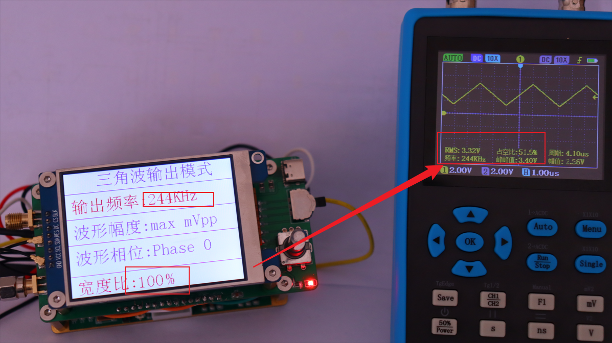


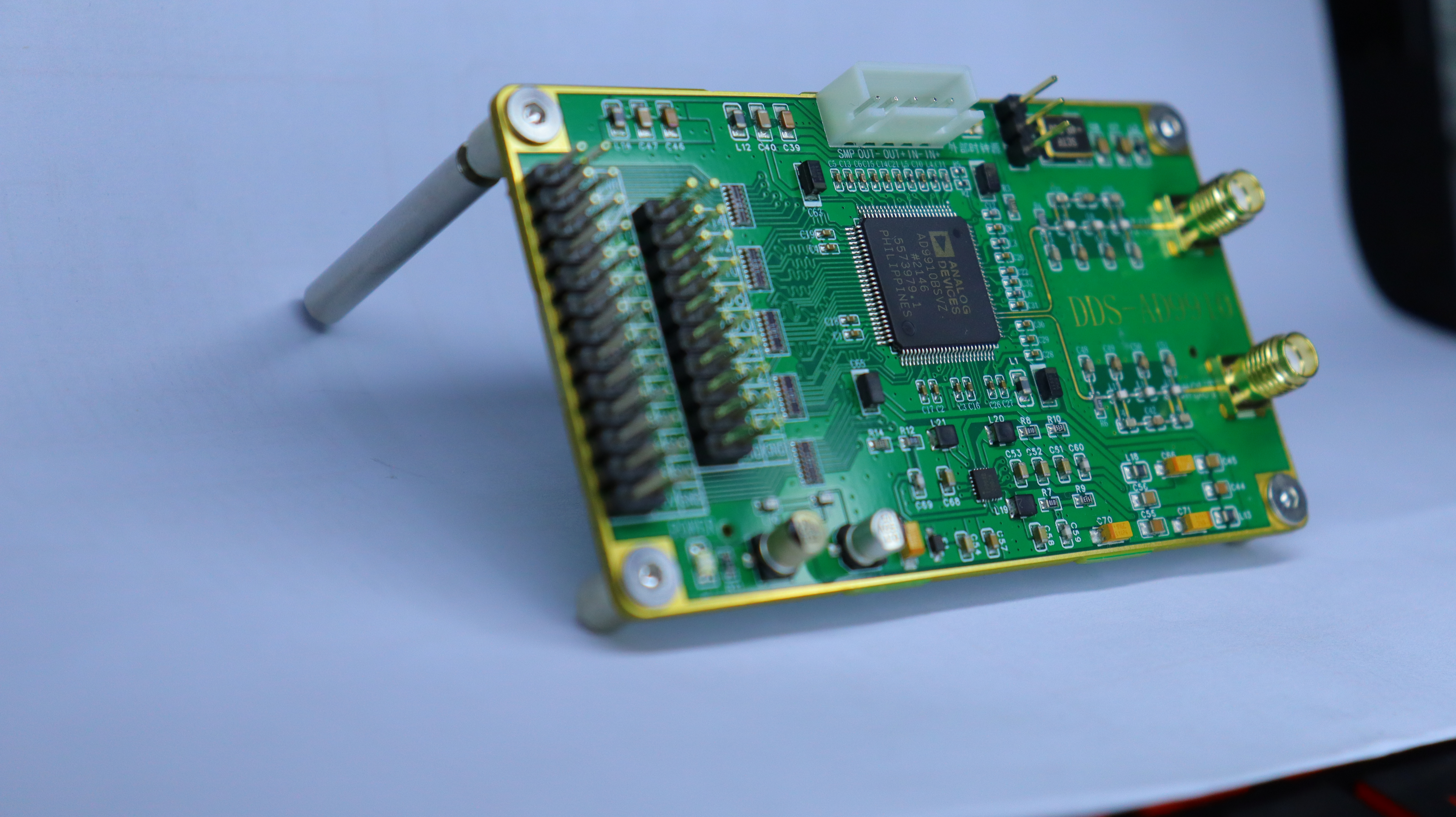
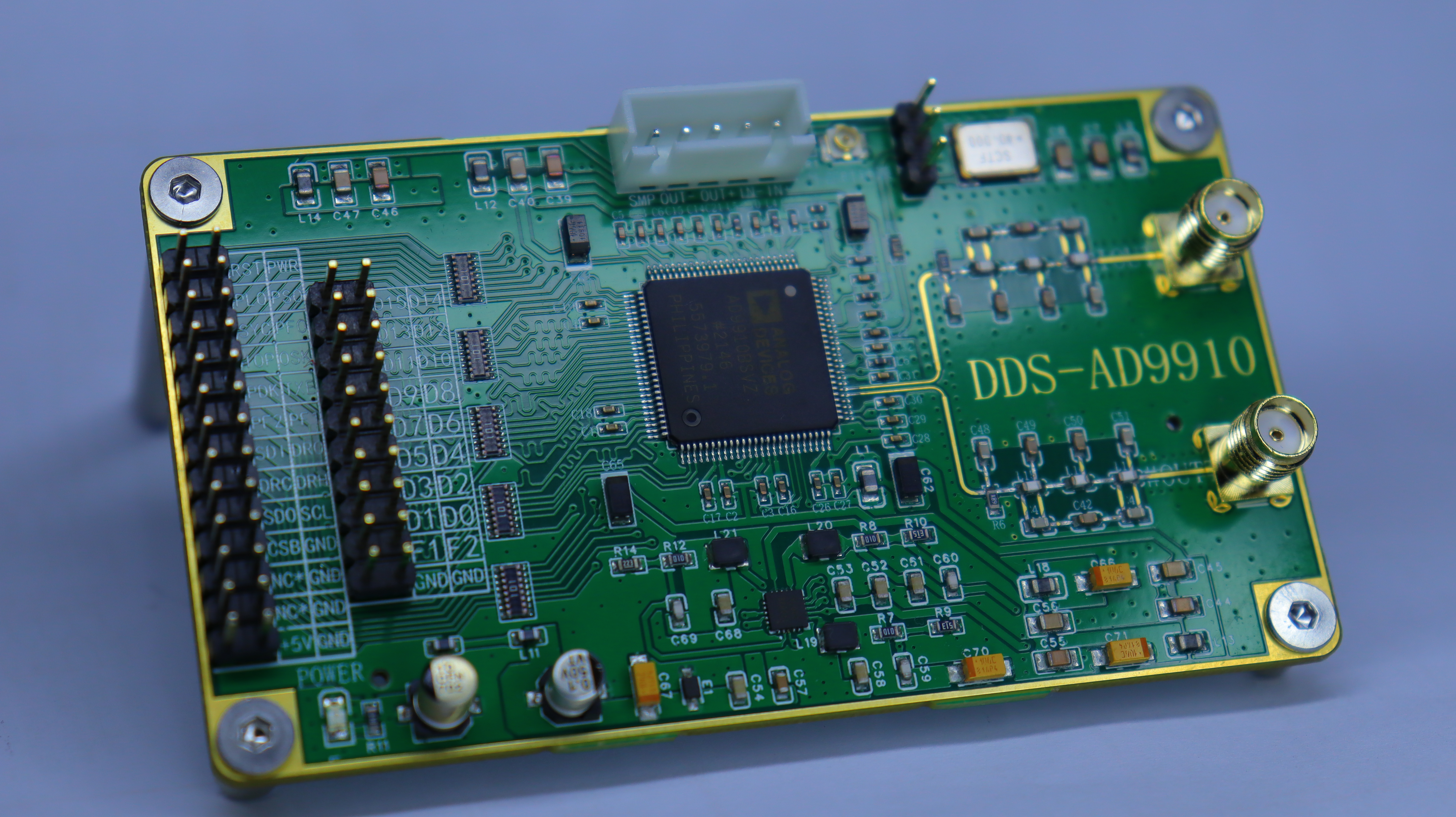


 It's worth noting that the AD9910 has many I/O interfaces due to considerations for other scenarios during its design. However, if you only use it to communicate with low-speed devices like STM32, you can connect fewer than 10 driver I/Os, significantly reducing the PCB area occupied by I/Os. You can refer to AD9910 module design diagrams found on Taobao, including those from the Tianjin-based Kodite store. I'll only briefly describe their products here. When
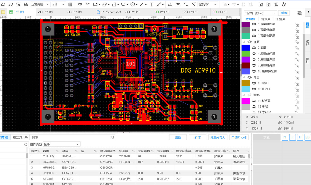


 The outer edging was originally intended to be metal-based, but that's too expensive... a bit unaffordable!
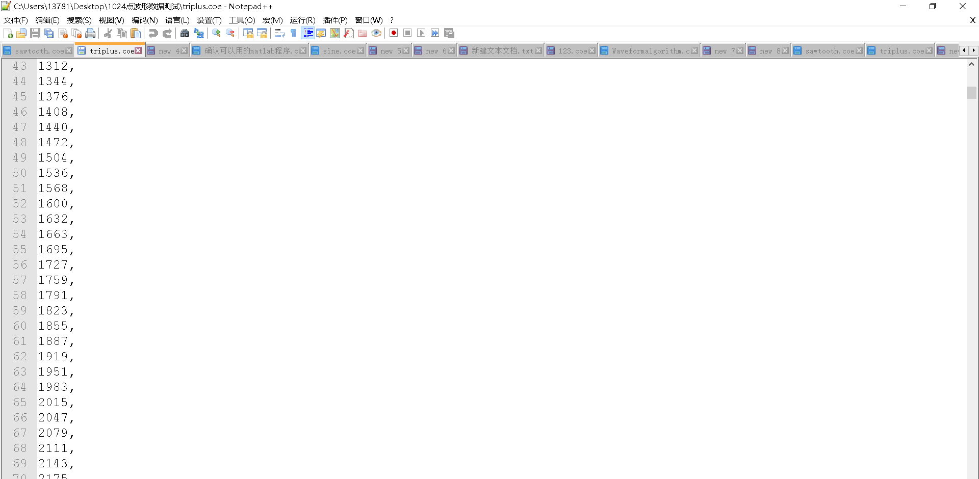
 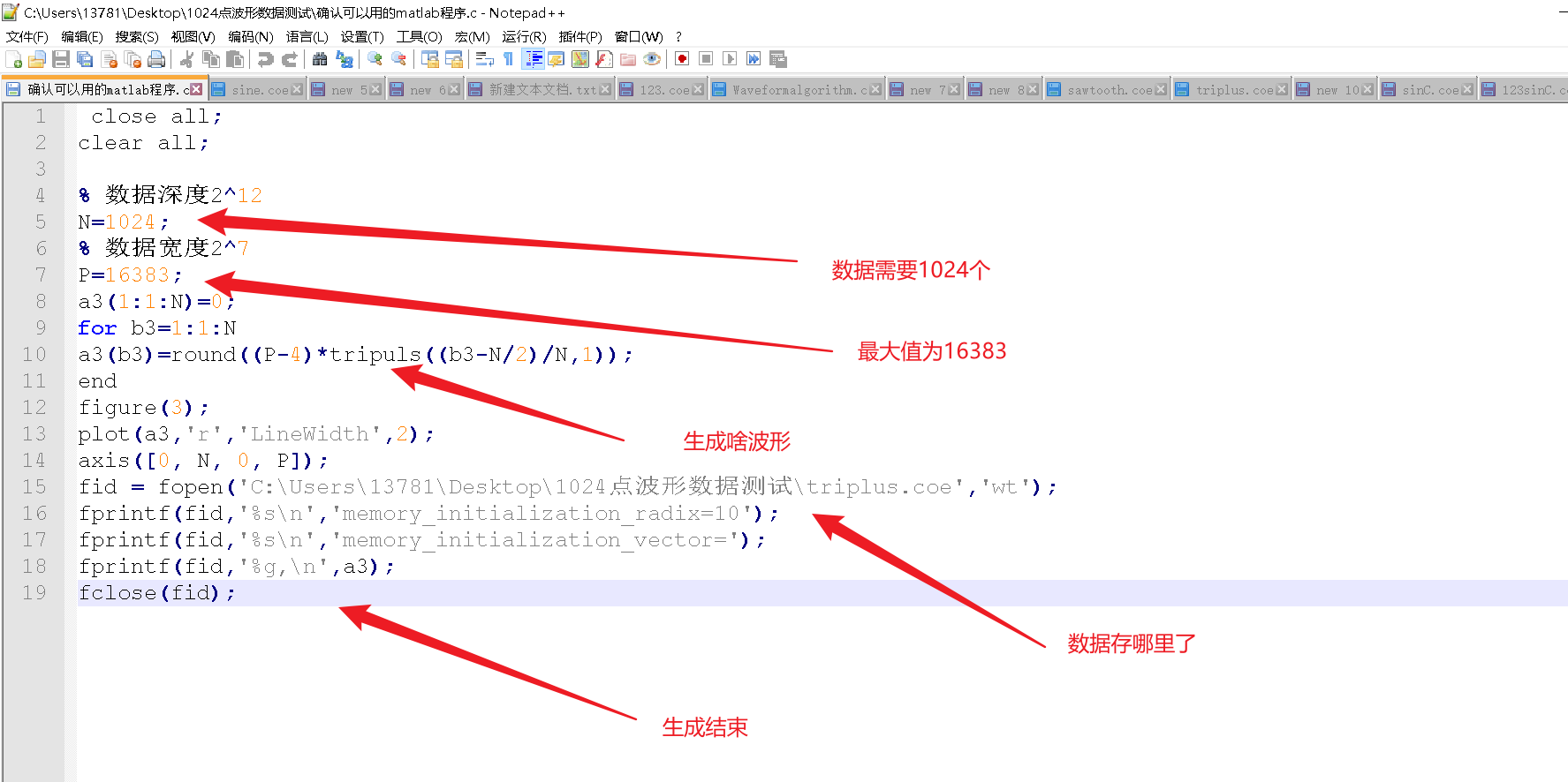 . It provides reference code for generating triangular wave function waveform data. `


All reference designs on this site are sourced from major semiconductor manufacturers or collected online for learning and research. The copyright belongs to the semiconductor manufacturer or the original author. If you believe that the reference design of this site infringes upon your relevant rights and interests, please send us a rights notice. As a neutral platform service provider, we will take measures to delete the relevant content in accordance with relevant laws after receiving the relevant notice from the rights holder. Please send relevant notifications to email: bbs_service@eeworld.com.cn.
It is your responsibility to test the circuit yourself and determine its suitability for you. EEWorld will not be liable for direct, indirect, special, incidental, consequential or punitive damages arising from any cause or anything connected to any reference design used.
Supported by EEWorld Datasheet
EEWorld
subscription
account

EEWorld
service
account

Automotive
development
community

Robot
development
community

About Us Customer Service Contact Information Datasheet Sitemap LatestNews


Room 1530, 15th Floor, Building B,
No.18 Zhongguancun Street,
Haidian District,
Beijing, Postal Code: 100190
China
Telephone: 008610 8235 0740
 京公网安备 11010802033920号

 BSSH-209-S-08-GT


