Project description: The STM32F103C8T6 minimum system board uses a CH340C USB-to-serial chip with a built-in crystal oscillator. It has a 5V to 3.3V LOD with a maximum current of 1A, and a SWD download interface. BOOT0 and BOOT1 have leads to facilitate the user to set various settings. In this mode, most of the pins of the microcontroller are led out with 2.54mm pin headers to facilitate connection with external circuits. The pins are marked on the back of the PCB. This minimum system board can be downloaded with one click. One click refers to clicking on the computer. You can download it.
Circuit introduction: This system is a minimum system circuit of a single-chip microcomputer, which has an additional USB to serial port circuit. The serial port circuit can control the potential of BOOT and control the reset circuit through an external transistor to realize downloading and automatic running of user programs after downloading.
 Inside the red circle 1 is the USB to serial port circuit. There is no crystal oscillator to reduce the board area. A TVS transient suppression diode is added at 5V to prevent the CH340C chip from being damaged by excessive instantaneous voltage. Inside the red circle 2 is a 5V step-down 3.3V LDO low-dropout voltage regulator. Red circle 3 is the automatic download and automatic operation control circuit.
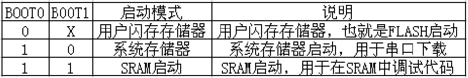
 To understand the automatic download and automatic operation control circuit, you must first understand the startup configuration setting mode of STM32. I am using the serial port download, so I set BOOT0 to high level and BOOT1 to low level through jumpers. In the circuit in red circle 3, Q2 controls BOOT0 to be high level. Q1 is used to reset the microcontroller to run the user program. You can see it by looking at the timing diagram below. When USB is using serial port communication to download the program, DTR and RTS respectively. First, DTR maintains a high level for almost more than 100 milliseconds and then turns to a low level. RTS remains at a low level until the program is downloaded. Then DTR and RTS are both high at the same time. When RTS is low, it just passes. Q2 sets BOOT0 to high level to realize serial port mode download. BOOT1 requires the user to set low level through short-circuit jumper. After downloading the user program, DTR will be set to high level earlier than RTS, and Q1 will lead Pass, pull down the NRST voltage to achieve reset, Q2 will also be cut off. The BOOT0 pin has a 100K resistor to ground and is set to low level, then the microcontroller will be in the user flash memory storage mode. At this time, the capacitor of the reset circuit will slowly fill up. , you can slightly increase the pull-up resistor of the reset circuit.


PCB blank board


There is a lighting program uploaded in the attachment. Use the PC13-GPIO pin to connect a 470R resistor and a light-emitting diode to the 3.3V positive power supply to flash. The ISP download software uses domestic software. When automatically downloading, everyone must set the same settings as those in the red circle, otherwise the download will not be successful. BOOT1 must be set to ground level, BOOT0 must also be set to low level, and the rest It’s nothing, you can search and download it online.

https://lceda.cn/editor#id=|155c0dd211864e7a898e98eeff06e930|9b454d15e54c4d58b8d53d1b00495dc2Open source

All reference designs on this site are sourced from major semiconductor manufacturers or collected online for learning and research. The copyright belongs to the semiconductor manufacturer or the original author. If you believe that the reference design of this site infringes upon your relevant rights and interests, please send us a rights notice. As a neutral platform service provider, we will take measures to delete the relevant content in accordance with relevant laws after receiving the relevant notice from the rights holder. Please send relevant notifications to email: bbs_service@eeworld.com.cn.
It is your responsibility to test the circuit yourself and determine its suitability for you. EEWorld will not be liable for direct, indirect, special, incidental, consequential or punitive damages arising from any cause or anything connected to any reference design used.
Supported by EEWorld Datasheet
EEWorld
subscription
account

EEWorld
service
account

Automotive
development
community

Robot
development
community

About Us Customer Service Contact Information Datasheet Sitemap LatestNews


Room 1530, 15th Floor, Building B,
No.18 Zhongguancun Street,
Haidian District,
Beijing, Postal Code: 100190
China
Telephone: 008610 8235 0740
 京公网安备 11010802033920号

 103R-820KB


