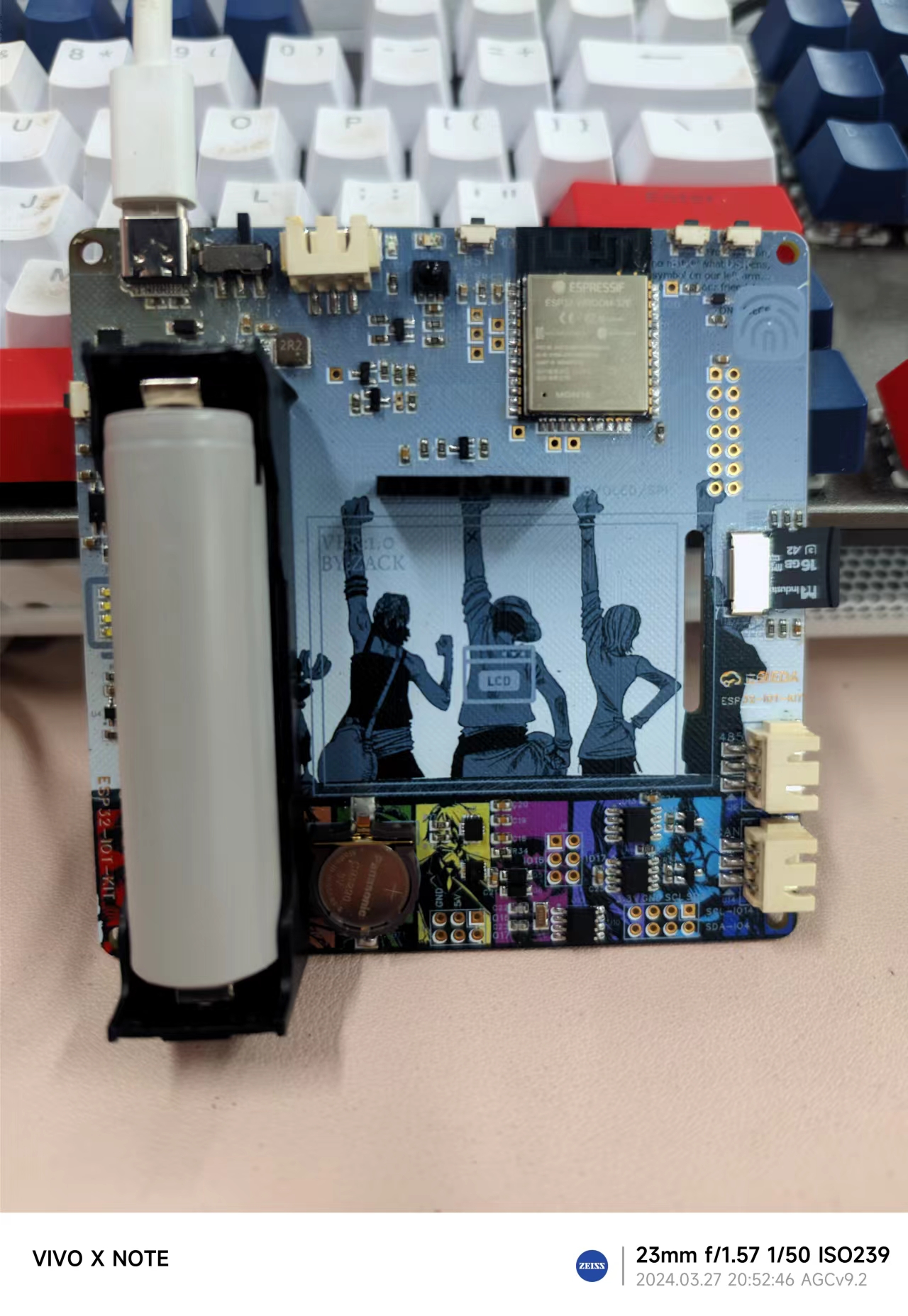
This "To Youth – Dream-Building ESP32 Learning Board"
is a replica of @mazhiliang's "ESP32-IOT-KIT Fully Open Source IoT Development Learning Board" project (project verification completed). The development board uses the ESP32-WROOM-E module as the main controller and supports communication methods such as WIFI, Bluetooth, Ethernet, RS485, and CAN. I personally plan to learn IoT development using MicroPython on the Thonny IDE. This differs slightly from the original developer's open-source learning plan.
Since I am still in the learning stage, I strongly recommend that those who want to systematically learn and replicate this project refer to the original developer's open-source project. The original developer provides a supporting Easyio driver library and CSDN blog tutorials, guiding everyone from ESP-IDF to IoT learning and development. The hardware and software introductions and guidance are very comprehensive and detailed. Original developer's open-source link: ESP32-IOT-KIT Fully Open Source IoT Development Learning Board.
The detailed introduction below is mainly taken from the original developer's article, with modifications and innovations noted.
The hardware peripherals have been upgraded.
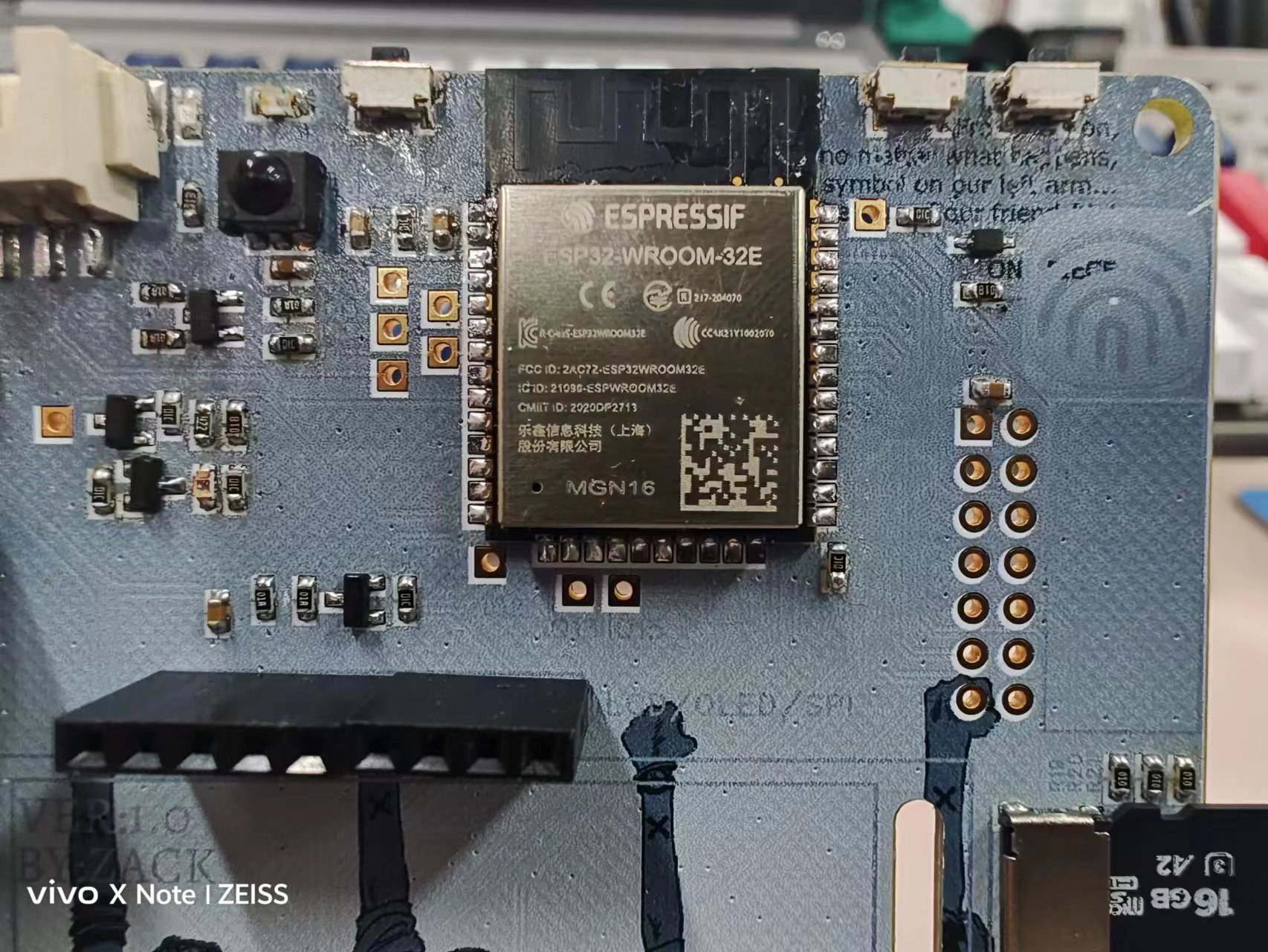
The ESP32 module has been changed from WORWER-E to WROOM-32E, removing PSRAM and adding two IOs:
ADC * 2 (battery, light; power is programmable),
4 buttons (BOOT, user buttons, and two more for reset and battery level indication)
, 1 touch button, and
1 user LED (same as the IO expansion WS2812B LED strip)
. It also includes 38kHz infrared receiver and transmitter,
RS485, and CAN (multiplexed with the IO, can also be multiplexed for UART, etc.). The circuitry has been upgraded, with the 2-pin terminal becoming a 3-pin terminal and the addition of GND. ESD protection has been added. The RS485 chip MAX3485 has been replaced with MAX13487.
4 I2C peripherals (ICM-20600 six-axis inertial measurement unit, SHT30 temperature and humidity sensor, PCF8563 - RTC, and a capacitive touchscreen FPC socket on the back)
2.0-inch single-point capacitive touchscreen (320*240 resolution. LCD screen uses SPI and capacitive touch I2C)
LCD/OLED/SPI expansion interface. I2C expansion interface. 3.3/5V power expansion interface.
TF card interface. (MicroSD)
Ethernet expansion interface. (Can connect to LAN8720 Ethernet module)
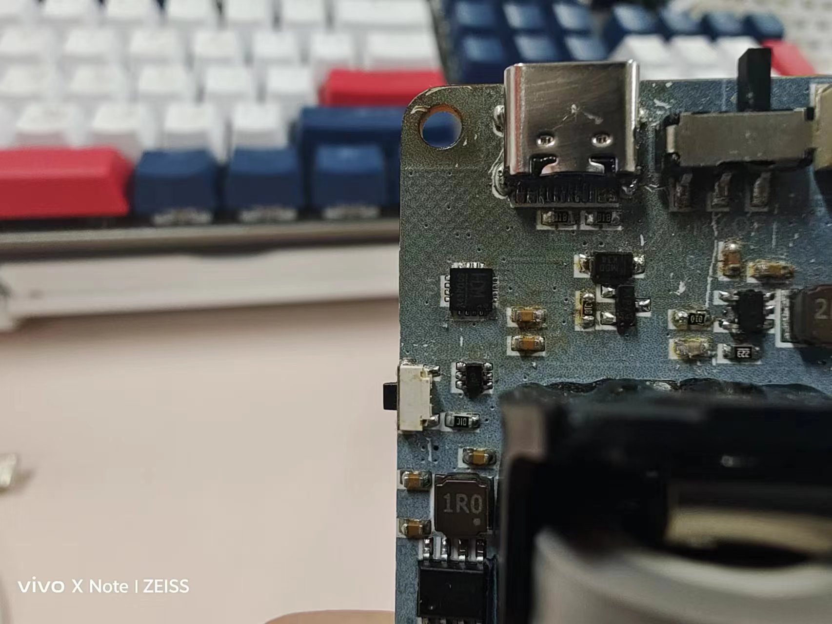
Type-C power, download, and debug interface.
Onboard CH343P automatic download circuit. Upgraded from the original CH340 USB to TTL circuit, smaller, faster, and more stable.
Onboard 18650 battery holder, lithium battery protection IC, and charge/discharge power management chip, providing 2A power output of 3.3V and 5V using only the onboard battery. The 3.3V voltage rail is a UPS, ensuring uninterrupted operation of the onboard hardware.
Hardware Features:
The board features an onboard ESP32-WROOM-32E dual-core 240MHz microcontroller, enabling development and application of Wi-Fi, Bluetooth, and Ethernet.
All onboard ESP32 I/O pins are exposed for easy debugging and expansion.
The PCB measures only 9.8 * 9.8cm, compact yet fully functional.
It supports expandable LAN8720 100Mbps Ethernet, conveniently located in the upper right corner header for wired Ethernet expansion. The
2.0-inch capacitive touchscreen is a combination of ST7789V and FT6236U, featuring IPS full-viewing angle and single-point capacitive touch, offering significantly better feel and lifespan than resistive touchscreens.
For those on a budget who prefer not to use a capacitive touchscreen, a row of SPI expansion interfaces is provided on the front for connecting LCD/OLED displays, compatible with many display modules available online.
An onboard 18650 battery holder provides lithium battery protection and charge/discharge management. When the power switch is on, the 3.3V supply is uninterrupted, preventing the ESP32 from restarting due to USB plugging or unplugging.
It features a Type-C interface for charging and downloading/debugging, with an onboard CH343 fully automatic download circuit. Connecting to a computer only requires a Type-C cable; no additional downloader is needed.
It integrates a six-axis IMU accelerometer/gyroscope (ICM-20600), an SHT30 temperature and humidity sensor, a PCF8563 independent RTC, infrared transceiver, and a light sensor, enabling comprehensive smart home solutions.
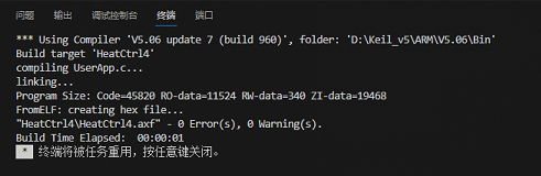
Currently, serial port connections are verified to be normal, and program downloading and burning are quite stable. Simple I/O port control applications function normally.

Power circuits such as lithium battery charging and automatic battery-to-power switching have also been tested and found to be stable.

0599127d68898bb8da76f7caae0b0d3d.mp4
PDF_To Youth—Dream Weaving ESP32 Learning Board.zip
Altium_To Youth—Dream Drawing ESP32 Learning Board.zip
PADS_To Youth - Dream Weaving ESP32 Learning Board.zip
BOM_To Youth—Dream Drawing ESP32 Learning Board.xlsx
95528
USB to Serial Port CH343g
USB to serial port programmer
The CH343G has a simple external circuit. Referring to the official documentation of Nanjing Qinheng Microelectronics Co., Ltd., all interfaces are brought out. The commonly used interfaces are RXD and TXD, while others can be left floating. All capacitors, resistors, and LEDs are 0805 packages for easy soldering. The interface is a mic-USB interface. Generally, the chip is programmed at 3.3V, with jumper VIO-V3. A 5V jumper VIO-5V is required, which has been verified.
CH343SER driver.EXE
uartassist5.0.10 serial port debugging.zip
Artery_ISP_Programmer_V2.0.12 burning software.zip
TCICP_V6.87_burning software.zip
27399c3c8c9cddc02f7fad017121e8de.mp4
PDF_USB to Serial CH343g.zip
Altium_USB to Serial CH343g.zip
PADS_USB to Serial CH343g.zip
BOM_USB to Serial CH343g.xlsx
95529
USB 3.0 HUB Expansion Dock Based on TUSB8041
TUSB8041 main controller, dual power supply
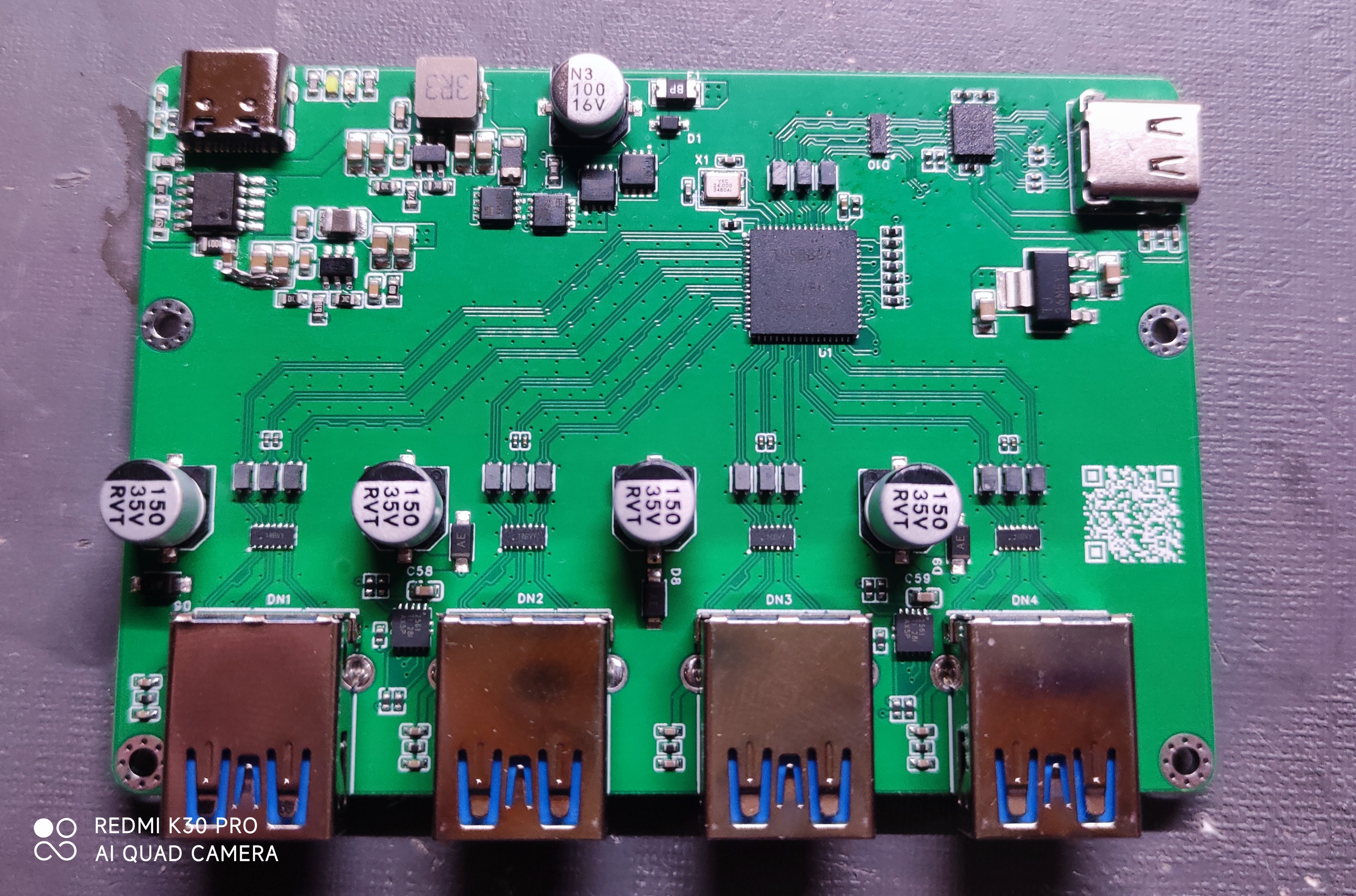
Figure 1 Original physical image
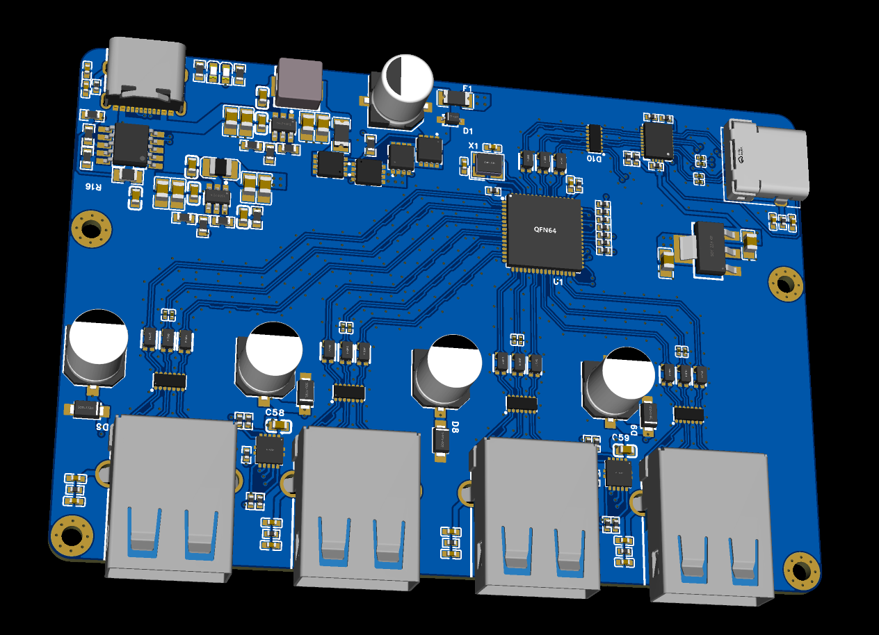
Figure 2 Revised 3D drawing
Using JLCPCB's four-layer 3313 laminated structure,
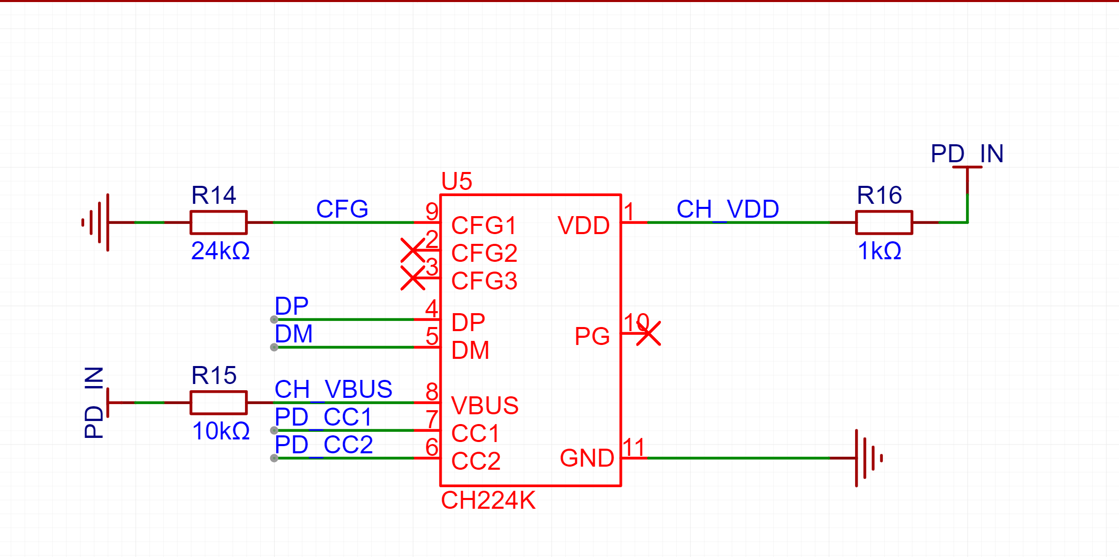
the power supply section has been revised with a 1.6mm board thickness. When drawing the schematic, a capacitor was forgotten at CH224K, causing it to not work. A jumper wire was added and tested, and it works fine. The open-source version has been corrected.

(a)
(b)
Figure 3 Forgotten capacitor
The power switching section is implemented using two PMOS and two NMOS. The LED lights up on whichever side has power. It is recommended to use LEDs of different colors for differentiation.
The 1.1V power supply has an RC delay start to meet the power-on sequence required by the main controller.
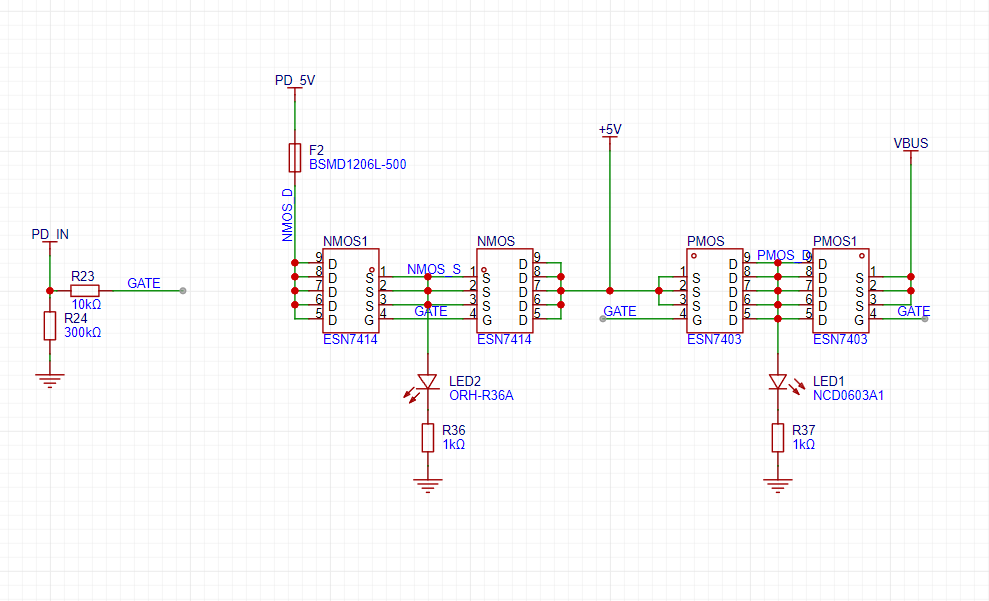
Figure 4 Power switching circuit
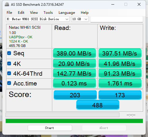
The speed was tested using a Netac WH61 hard drive enclosure (Figure 5(a)). The speed of the hard drive enclosure directly connected to the computer is shown in Figure 5(b).
(a)
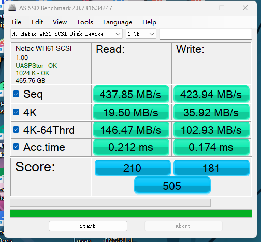
(b)
Figure 5 Speed test
This design uses JLCPCB's free PCB+SMT fabrication. Except for VL160, all can be purchased from the LCPCB online store.
Because SMT was used, some capacitors were in 0201 packages, which are more difficult to solder. Those who are making their own boards and soldering them themselves can replace them with 0402 package capacitors.
The USB 2.0 data cable on the CH224K side is for fast charging protocol communication; the speed is not high, and strict length matching is not required. Please ignore the DRC error here.
PDF_USB 3.0 HUB Expansion Dock Based on TUSB8041.zip
Altium_USB3.0 HUB Expansion Dock Based on TUSB8041.zip
PADS_USB 3.0 HUB Expansion Dock Based on TUSB8041.zip
BOM_USB 3.0 HUB Expansion Dock Based on TUSB8041.xlsx
95531
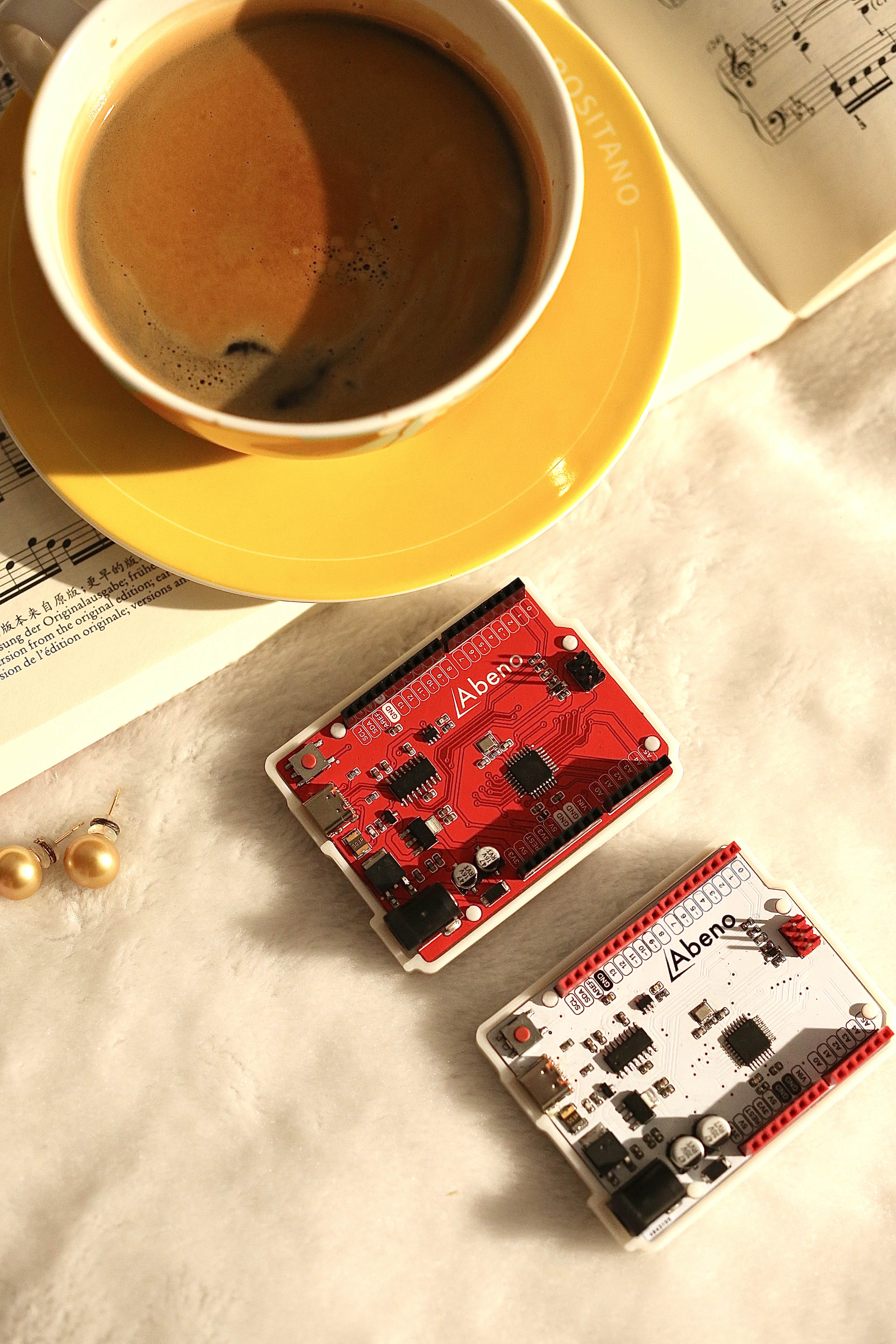
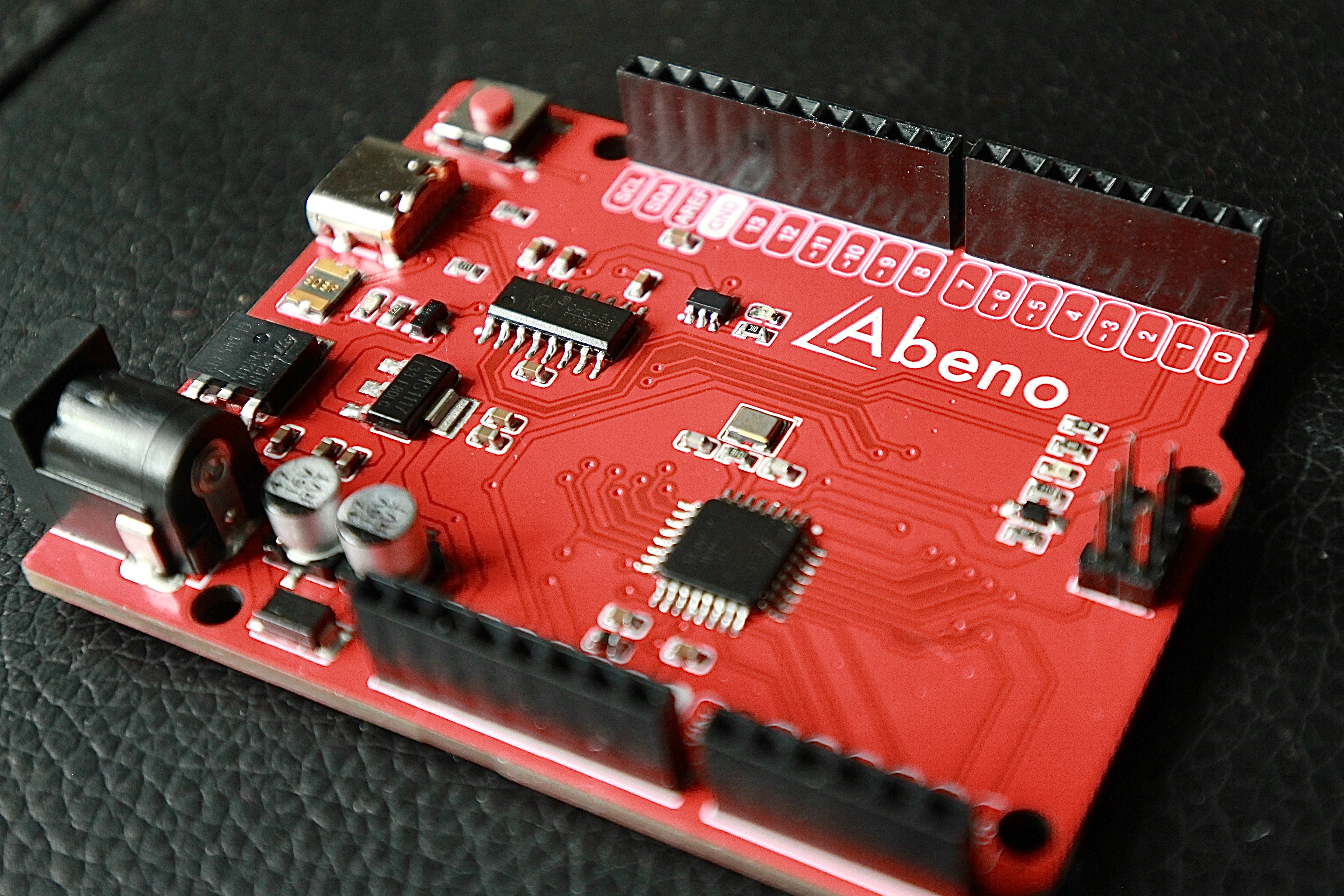
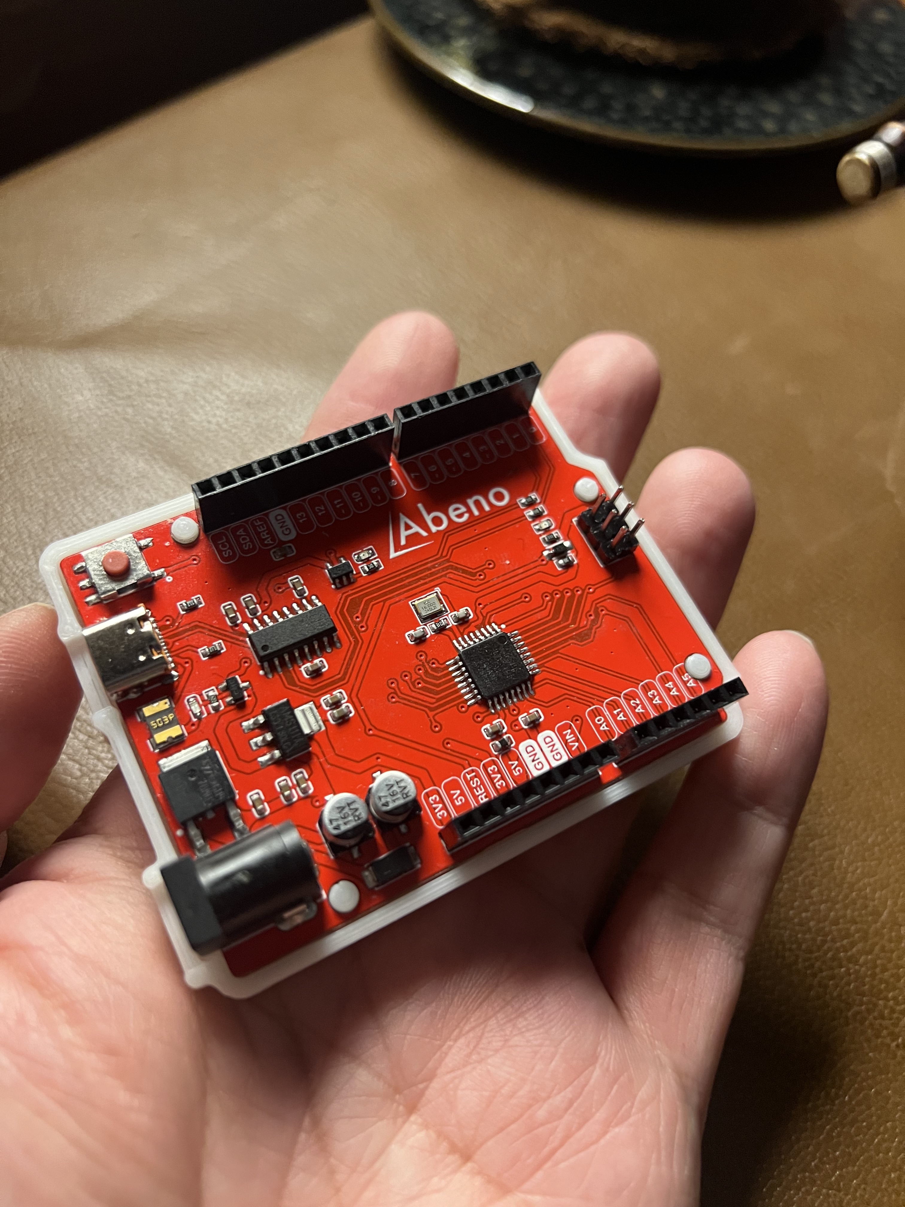
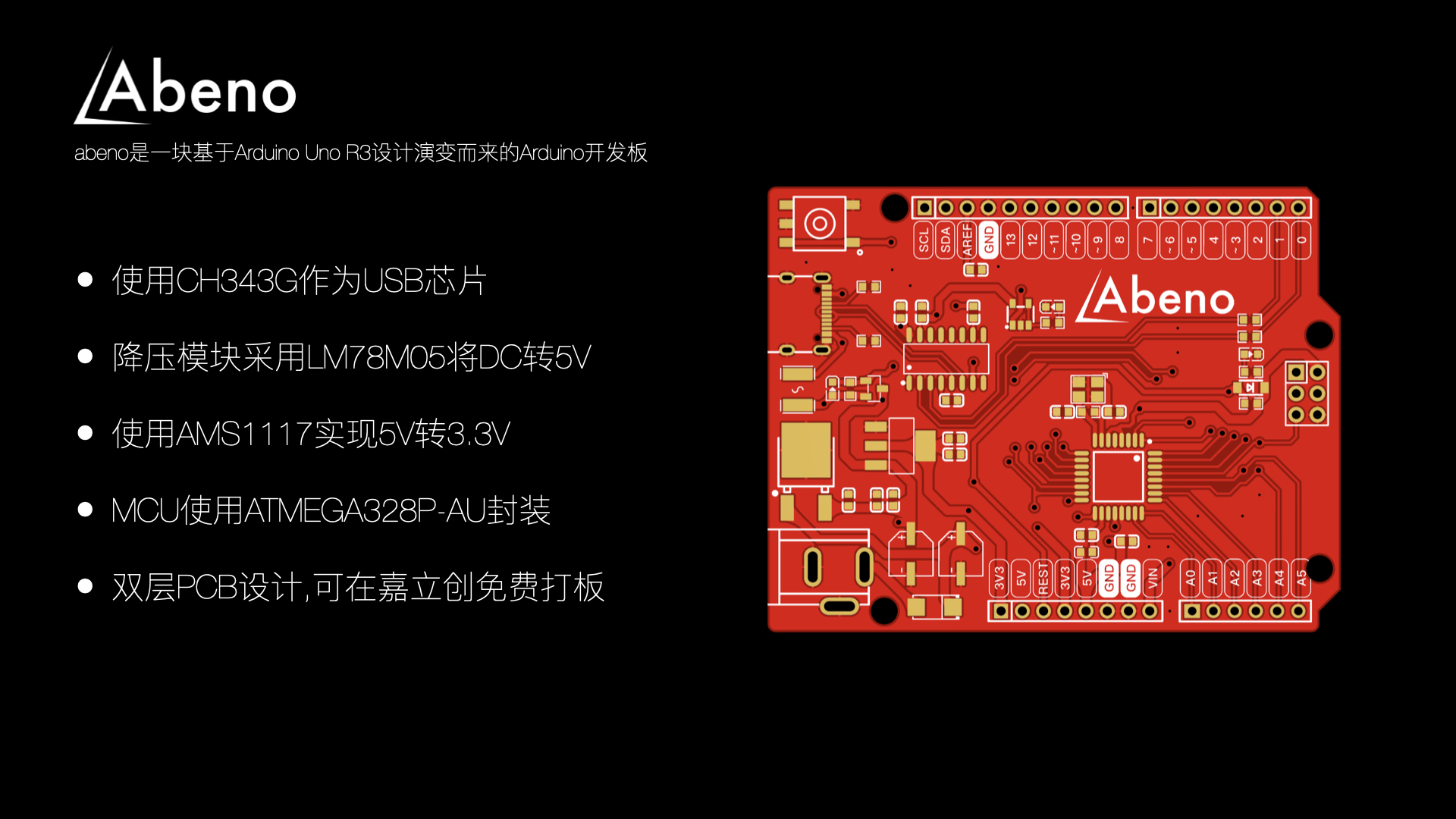
Abeno: A simple Arduino development board
Arduino Uno version CH343G / AMS1117 / 78M05 / ATmega328p-AU
copy_F29FA8D4-E98D-4D15-8B5D-254F45A924CF-Wi-Fi (High).mp4
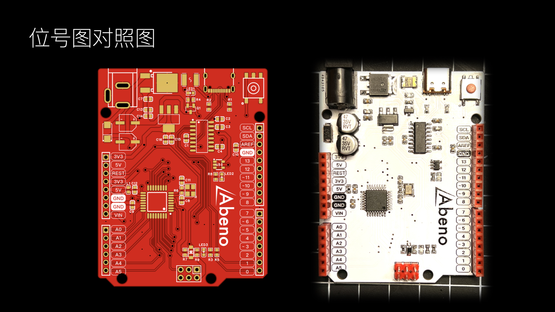
BOM and tag number diagram (printed version).pdf
Abeno Instructions.pdf
hardware.zip
AbenoShell.3mf
PDF_Abeno A Simple Arduino Development Board.zip
Altium_Abeno: A simple Arduino development board.zip
PADS_Abeno - A simple Arduino development board.zip
BOM_Abeno A simple Arduino development board.xlsx
95532
Temperature control equipment 1.0
STM32-based temperature control device with OLED, A24C64 memory, CH340E serial port, TJA1050 CAN communication, PD12V decoy, etc.
For educational purposes only, not for commercial use.
This project is a temperature control device based on the STM32F103CBT6 and FreeRTOS system. Peripherals and functions used include an SPI OLED screen, TJA1050 CAN communication, CH340E serial communication, a five-way button, ADC, PID control of PWM output, IIC AT24C64 storage, CH224K PD12V decoy, and step-down.
A 3D-printed extruder head is used as a load to demonstrate the functionality. The main purpose of this project is to practice using FreeRTOS, IIC, SPI, and CAN protocols.
Code link:
https://github.com/cnxft/Temperature_Control_Equipment/tree/main
I. Overall Design Block Diagram
Power Supply:
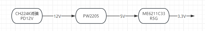
Others:

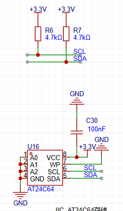
II. Hardware Circuit Composition
1. AT24C64 memory section, chip and its IIC pull-up
2. 12864 OLED screen SPI wiring

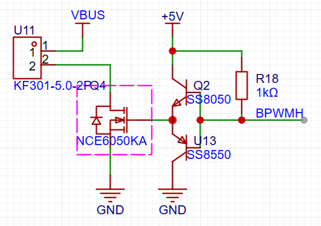
3. PWM control output size circuit
III. Program Flowchart
The following content is initialized or started before starting the FreeRTOS task scheduler:
HAL_ADCEx_Calibration_Start(&hadc1);
HAL_ADC_Start_DMA(&hadc1, (uint32_t *)&dmaadc, 3);
HAL_TIM_Base_Start_IT(&htim2);
HAL_TIM_PWM_Start_IT(&htim2, TIM_CHANNEL_1);
HAL_TIM_PWM_Start_IT(&htim2, TIM_CHANNEL_3);
NTC1save_init(ntc1save);
Key_Loading();
userShellInit();
CAN_SetFilters();
HAL_CAN_Start(&hcan);
u8g2Init(&u8g2);
A progress bar then appears on the OLED screen, its length increasing as parameters are retrieved from the AT24C64.

This project uses the FreeRTOS system, making the overall design relatively simple. A total of 7 tasks are used:
void AppTask_App(void *argument);
// Reads the NTC value and calculates
void AppTask_OutPut(void *argument);
// Calculates the duty cycle of the output PWM waveform using the PID algorithm
void AppTask_MessSend(void *argument);
// Sends CAN, serial port messages, and saves data to the AT24C64
void AppTask_SerCom(void *argument);
// Uses the shell_letter open-source library
void AppTask_CanCom(void *argument);
// Receives messages via polling CAN
void AppTask_Key(void *argument);
//Using the multi_button open-source library to generate a 5ms tick
void AppTask_Menu(void *argument);
//The program that drives the OLED screen
1. Task content
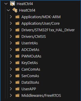
Each task is written in a file under UserApp, which you can check yourself
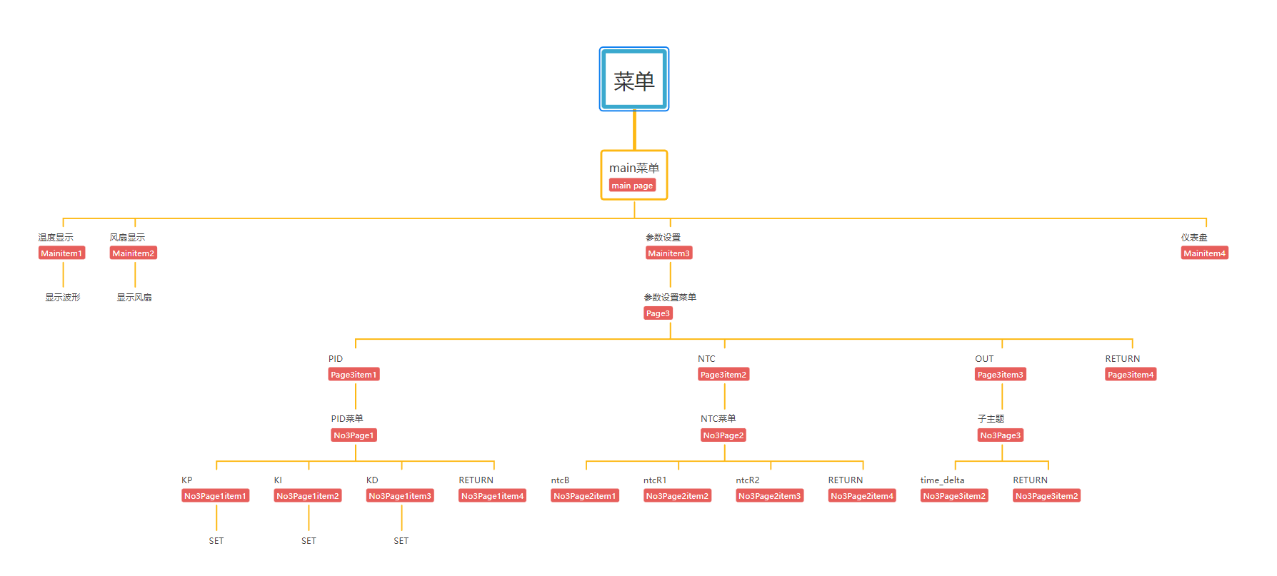
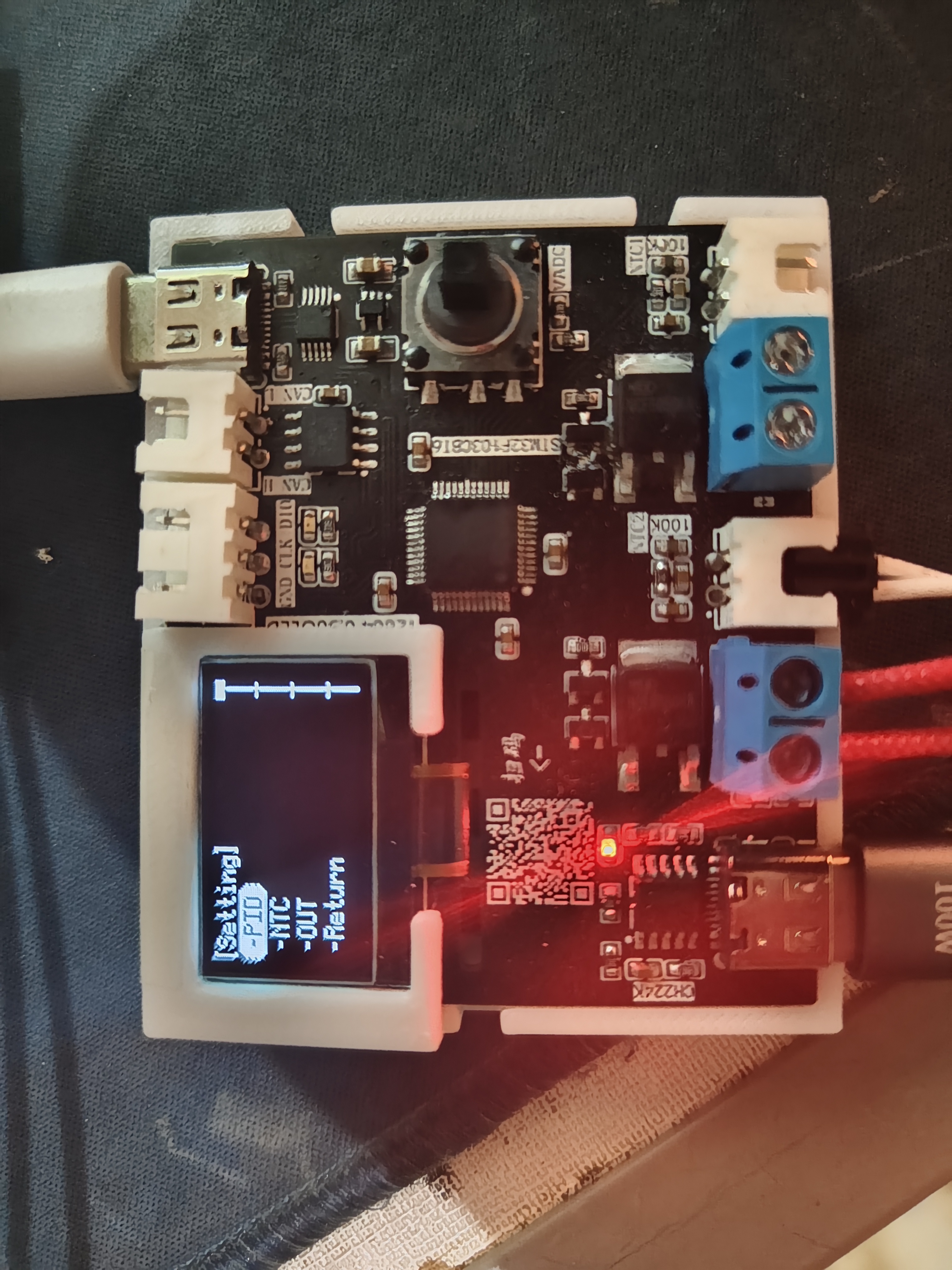
2. OLED menu division
The OLED screen uses an open-source program from a Bilibili user. The idea is to make it into a linked list, which can point to the next level menu or to the interface you want to create (function form).
A simple menu list is written
3. u8g2 initialization
The callback function for driving the OLED is written in the oled.c file. u8g2 initialization:
u8g2_Setup_ssd1306_128x64_noname_f(u8g2, U8G2_R0, u8x8_byte_4wire_hw_spi, The `u8x8_stm32_gpio_and_delay`
function indicates that 4-wire hardware SPI is used, and the SPI driver function from the HAL library is written in the corresponding position within the function.
The `u8x8_stm32_gpio_and_delay()` function is the GPIO and delay function when using software SPI/IIC. When using software, the HAL GPIO and delay functions should be written in this function, but since hardware is used here, the function directly returns 1.
Using the `setup` function built into the U8G2 library for SSD1306, there's no need to write it manually.
4. Menu switching:
When a key is pressed, the screen's running state changes, and the menu is refreshed or a specified function is opened based on the running state.
The key detection task is written in the `TaskKey` task, which generates a tick every 5ms to detect key presses. Then, the key detection results are placed in a pre-created queue.

The TaskMenu task calls the function to obtain the key status in blocking mode, with a blocking time of 200ms
(xQueueReceive(Queue_OLEDKeysHandle, &Dir, pdMS_TO_TICKS(200)) != pdTRUE)
(which can be understood as refreshing the screen every 200ms)
. 5. The
CAN interface does not have many functions or detailed operations. It only configures the following functions to send and receive normally. There are no functions
that use CAN. In the usercan.c file, the sending, polling, and filter configurations are all included.
The filter is configured in 32-bit mask mode. It will be modified later when there is a specific application.
6.
For the serial port, a letter_shell library is used, which can manipulate the device like a Linux shell.
In the shell_func..c file, several functions have been added. Commands can be used to call these functions to modify the values of kp, ki, and kd for more convenient parameter tuning.
SHELL_EXPORT_CMD(SHELL_CMD_PERMISSION(0) | SHELL_CMD_TYPE(SHELL_TYPE_CMD_FUNC), out_state, Shell_OUT, Enable output 1 or 0);
SHELL_EXPORT_CMD(SHELL_CMD_PERMISSION(0) | SHELL_CMD_TYPE(SHELL_TYPE_CMD_FUNC), out_target, Shell_Target, Set target temp double);
SHELL_EXPORT_CMD(SHELL_CMD_PERMISSION(0) | SHELL_CMD_TYPE(SHELL_TYPE_CMD_FUNC), parameter_show, Shell_Parameter_Show, show pid wushen);
SHELL_EXPORT_CMD(SHELL_CMD_PERMISSION(0) | SHELL_CMD_TYPE(SHELL_TYPE_CMD_FUNC), pid_reset, Shell_PID_Reset, pid reset wushen);
SHELL_EXPORT_CMD(SHELL_CMD_PERMISSION(0) | SHELL_CMD_TYPE(SHELL_TYPE_CMD_FUNC), kp_set, Shell_Kp, Set Kp float);
SHELL_EXPORT_CMD(SHELL_CMD_PERMISSION(0) | SHELL_CMD_TYPE(SHELL_TYPE_CMD_FUNC), ki_set, Shell_Ki, Set Ki float);
SHELL_EXPORT_CMD(SHELL_CMD_PERMISSION(0) | SHELL_CMD_TYPE(SHELL_TYPE_CMD_FUNC), kd_set, Shell_Kd, Set Kd float);
Although the parameters kp, etc., are of type double when defined, the library parameter of letter_shell is double, which will cause an error (0), while float is normal.
After connecting the serial port, you can press the Tab key or type help+enter to view the available commands. It's worth noting that when the function type is floating-point, the decimal point should not be omitted.
The logo can also be modified in the shell.c file.
See how beautifully I modified it?

7. ADC Acquisition:
Here, a formula method is used to calculate the current temperature based on the B value. The function name is: float ntc_count_value(ntcpar ntcx). This function is located in ntc.c. DMA is used to obtain the ADC value, and the ADC value is periodically obtained, calculated, and saved in AppTask_App.
8. Output
: The heating device is driven by a PWM-controlled transistor-controlled MOSFET. The PWM duty cycle is calculated by the PID algorithm. Here, the output on the left is used in conjunction with the temperature sensing resistor. The right side can use PWM to control fans, etc. The frequency division value and counting value settings are as follows. You can modify them according to your needs. When modifying the counting value, remember to modify the function that maps the PID calculation result to the PWM duty cycle part.

9. Data Storage and Retrieval
: A separate AT24C64 chip was designed to store the device parameters, including the values of kp, ki, and kd, the B value of the temperature sensing resistor, the resistance value of the voltage divider resistor of the temperature sensing resistor, the resistance values of the two resistors for voltage measurement, etc.
The data is stored on the AT24C64 chip in the following locations, including the starting address and the offset relative to the starting position.
/****************Relative address for storing data on AT24C64*******************/
#define DATE_FIRST_ADD 352 // First position for storing data
#define Date_OUTSTATE_SUM 0 // Difference from the initial position
#define Date_NTCB_SUM 1 // Relative difference 1
#define Date_NTCT25_SUM 3
#define Date_NTCMAXADC_SUM 7
#define Date_NTCR1_SUM 11
#define Date_NTCR2_SUM 15
#define Date_VADCMADC_SUM 19
#define Date_VDDA_SUM 21
#define Date_RESH_SUM 25
#define Date_RESL_SUM 29
#define Date_KP_SUM 33
#define Date_KI_SUM 41
#define Date_KD_SUM 49
#define Date_TARGET_SUM 57
#define Date_TIMEDELTA_SUM 65
#define Date_TOTAL_NUM 15
In the SaveAndRead_func.c file, two functions are defined:
HAL_StatusTypeDef Date_Init(uint8_t which_one);
HAL_StatusTypeDef Date_Save(uint8_t which_one);
These are used to save and read data respectively. A union variable is used in the functions to make saving and reading more convenient.
10. The progress bar
reads data before the for (;;) loop in AppTask_App, loading some necessary parameters into the program.
Initially, a synchronization function between programs in the FreeRTOS system was used, using notifications to simulate binary semaphores to synchronize AppTask_App and AppTask_Menu. The progress bar in the AppTask_Menu task will lengthen if it does not acquire a binary semaphore; otherwise, it enters a blocked state until the progress bar finishes and enters the menu interface.
11. Problems and Reflections
First of all, it should be said that this is not a perfect work; there are still many areas that need improvement in terms of functionality, program, and shell.
...To be continued...
Part Four: Physical Display
My soldering sequence: First, solder the back side using a soldering station. Second, solder the chip and two Type-C connectors, ensuring correct soldering. Third, solder the rest using a hot air gun, but pay attention to the Type-C connector placement. Alternatively, you can solder the PD12V decoy section first to test the effect; a successful decoy will light up the LED. Then solder the 5V to 3.3V converter. Finally, solder the screen and plug-in components.
Temperature curve
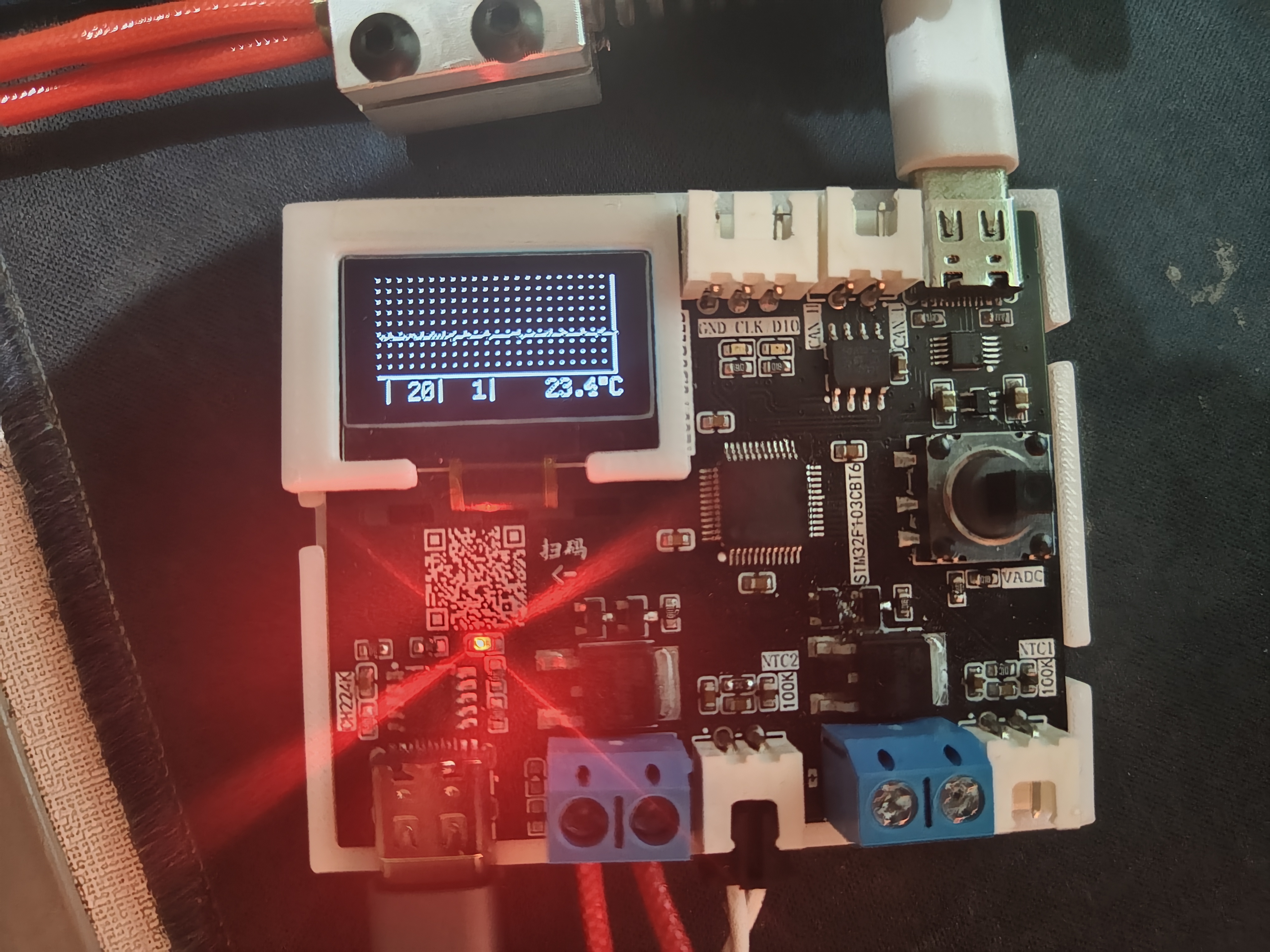
output settings (switch, target temperature, fan PWM duty cycle)

and PID KP
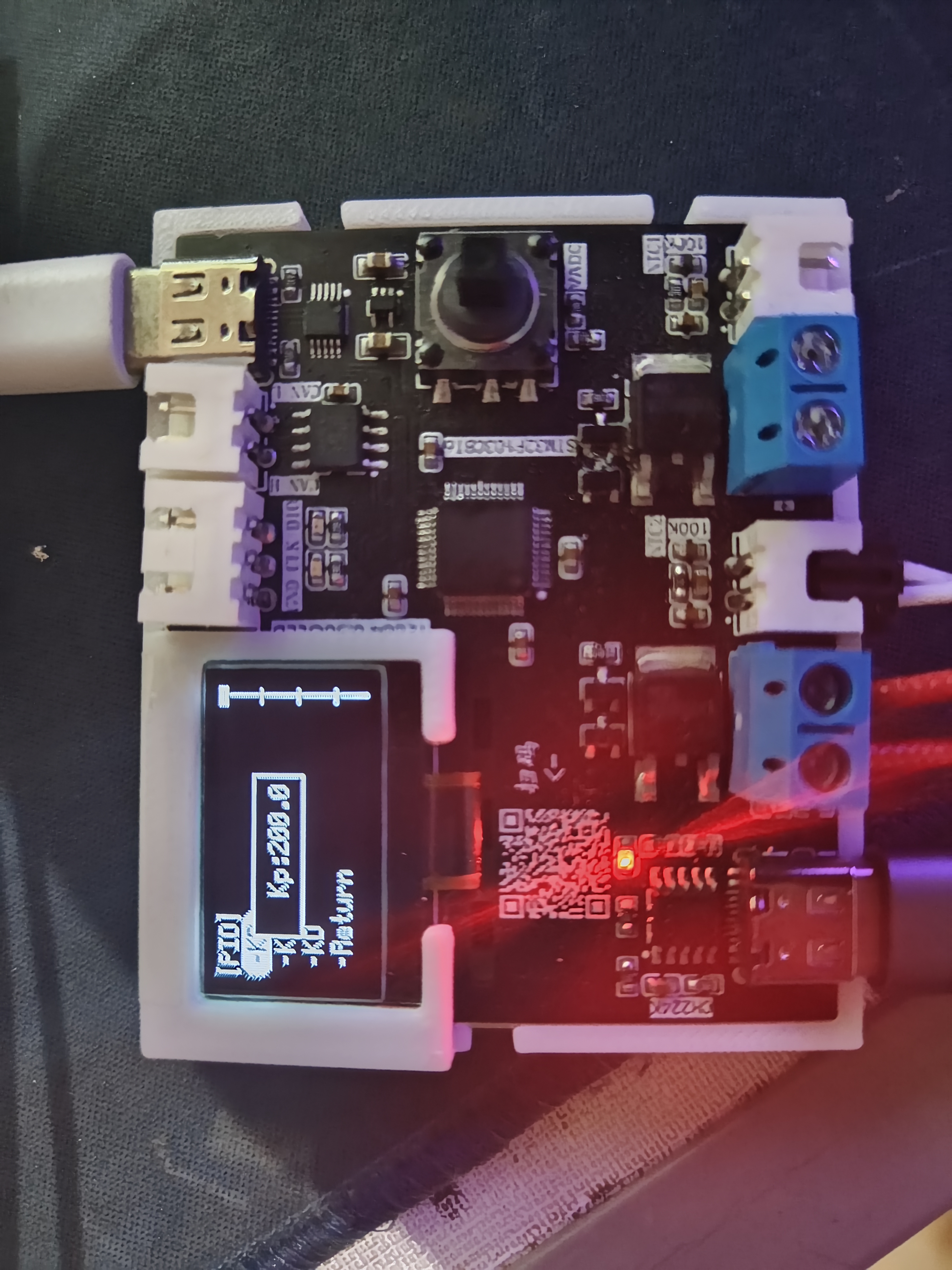
parameter display are included
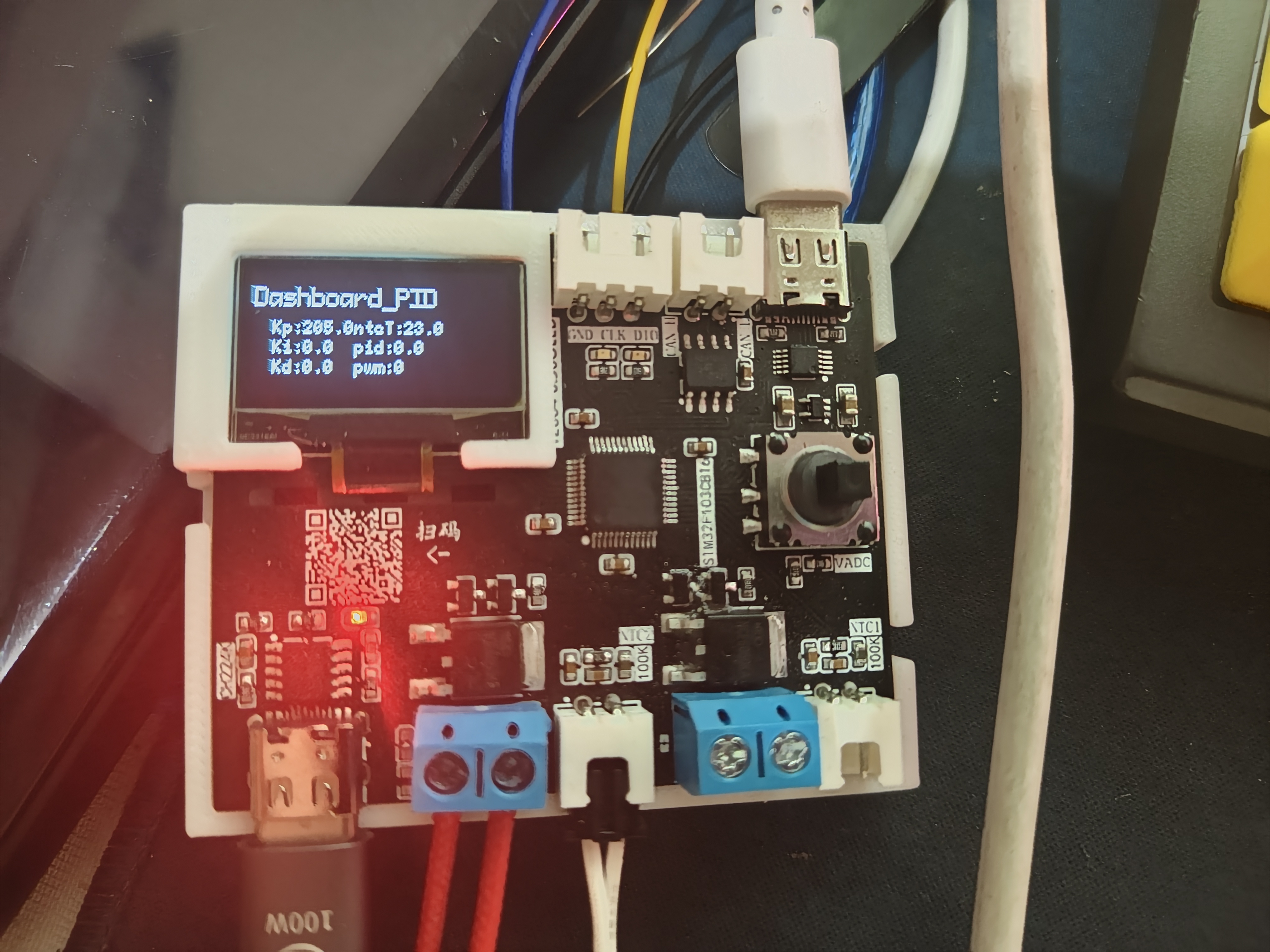

. The demonstration
video, located in the appendix, shows the usage of letter_shell and demonstrates parameter modification and automatic saving to the AT24C64.
Base 2.SLDPRT
shell.STL
bandicam 2024-03-28 20-00-33-611.mp4
PDF_Temperature Control Equipment 1.0.zip
Altium_Temperature Controller 1.0.zip
PADS_Temperature Controller 1.0.zip
BOM_Temperature Control Equipment 1.0.xlsx
95533
ST-Link
The detailed process of imitating Zhihui Jun's ST-Link
was posted on Zhihu: https://zhuanlan.zhihu.com/p/687542063
When the ST-Link
computer recognizes the ST-Link port
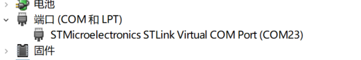
connected to the STM32 series chip, a file prompt will appear. You can drag the hex file into the folder to start the programming process.

00450bee8712930b2da378b9230ef89.jpg
PDF_ST-Link.zip
Altium_ST-Link.zip
PADS_ST-Link.zip
BOM_ST-Link.xlsx
95534
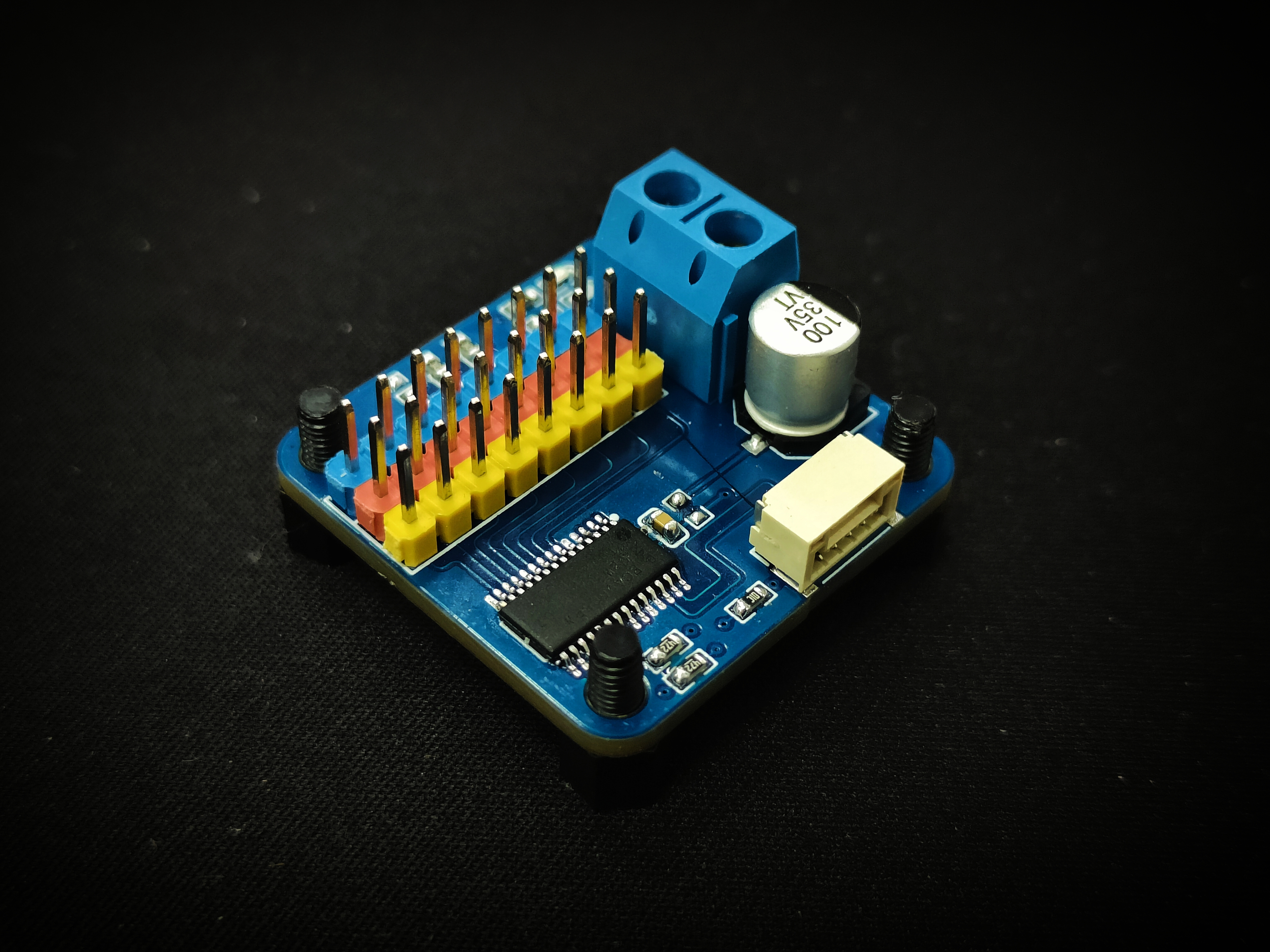
PCA9685 IIC-PWM controller module 30mm small board
PCA9685 IIC-PWM controller module 30mm small board
The PCA9685 IIC-PWM controller module is a 30mm small board.
The PCA9685 features 5 address configuration pins and 16 PWM outputs.
This project, considering practical needs, only uses three address configuration pins and eight PWM outputs.
PDF_PCA9685 IIC-PWM controller module 30mm small board.zip
Altium_PCA9685 IIC-PWM controller module 30mm small board.zip
PADS_PCA9685 IIC-PWM controller module 30mm small board.zip
BOM_PCA9685 IIC-PWM controller module 30mm small board.xlsx
95535
electronic


 京公网安备 11010802033920号

 18235WCD-13F-U632


