During hardware debugging, we often need to troubleshoot which electronic components are overheating.
Traditional methods not only dirty the PCB, but also make it difficult to locate small heat points.
Some open-source thermal imaging projects are based on the MLX90640, which looks good but has low resolution;
others are based on the Hikvision 4117, which has high resolution but the app is not smooth enough
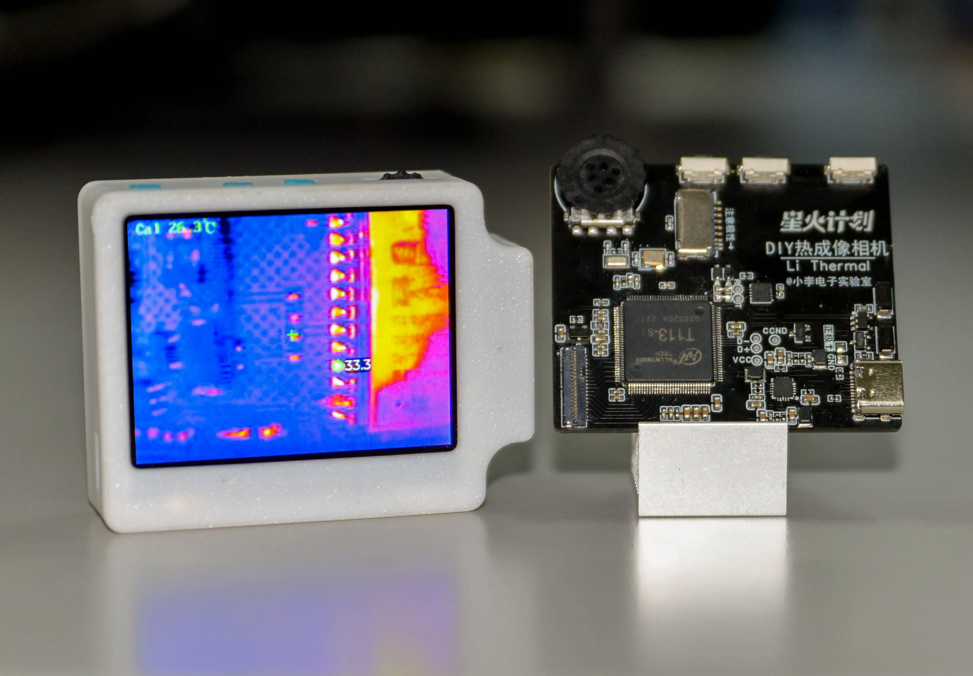
. Based on this, I wanted to combine the advantages of both and designed this thermal imaging camera.
It not only has the resolution of the Hikvision 4117, but is also smooth enough, with almost all animations reaching a 90Hz refresh rate and supporting interruption of animations. Moreover,
both the hardware and software are open source!
Bilibili demo video: https://www.bilibili.com/video/BV1e4xeeCEGL
Github open source link: https://github.com/diylxy/LiThermal
[Related images will be added after the National Day holiday]
Its functions include:
taking photos (capturing full-screen temperature data while taking photos),
recording videos
, viewing the album
, viewing maximum, minimum, and center temperature values,
temperature statistics charts,
modifying the color palette
, redirecting the backend management page (accessible via computer).
System configuration
: SoC: Allwinner T113-S3,
Frequency: 1 GHz * 2 cores
, Memory: 128MB on-chip,
Screen: 2.4-inch TFT LCD, 320x240 @ 94.3 Hz,
Thermal imaging refresh rate: 25Hz
, Temperature measurement range: 0-106.4 ℃ (not tested below zero, reportedly can measure down to -20 ℃) ,
Sensor resolution: 160*120,
Operating system: Allwinner Tina Linux, based on OpenWRT,
GUI: LVGL 8.
Replica Tutorial
Notes: This project involves soldering numerous 0402 components and pins with a 0.3mm pitch, making it slightly more difficult. Please be prepared. Before soldering, you will need a soldering iron, hot air gun, flux, and soldering tape.
【Hardware】
PCB Prototyping Parameters: Double-sided board, 1.2mm thickness.
Components are the same as in the BOM; simply purchase according to the specifications. PCB soldering precautions are marked on the PCB silkscreen layer. Please double-check the component orientation before soldering.
Screen Purchase Link: https://item.taobao.com/item.htm?id=577414614398
The screen connectors from LCSC are not very easy to solder; you can buy this instead: https://item.taobao.com/item.htm?id=717518604324
If you are not using a stencil, it is recommended to solder everything except the T113-S3 chip first to avoid damaging the T113 chip due to abnormal power supply output voltage. Test Method: Connect one end of R5 connected to the EA3036 to the VCC_PMU network, plug in the USB power supply, and measure the three output voltages of the EA3036 respectively: 1.5V, 3.3V, and 0.9V. If the voltages are incorrect, please check whether the three feedback (FB) pins of the EA3036 are poorly soldered.
After the power circuit test is normal, you need to program the 51 microcontroller first. Use a USB to serial port adapter to connect to the two serial port test points next to the STC8 microcontroller, and use STC-ISP software to program the hex firmware. It is recommended to disconnect the two 0-ohm resistors first during programming. The relevant project files are in the attachment at the end of the document or on GitHub.
Then test whether the microcontroller is working properly: with the USB power supply plugged in, press and hold SW1 for 3 seconds and measure whether the EA3036 has three power outputs. If not, check for poor soldering.
Finally, solder T113-S3.
To test if the T113-S3 is working properly: Insert the USB cable into the computer, press and hold SW1 for 3 seconds. If you hear a beep indicating a USB device is connected and the Device Manager finds a USB device without a driver, the T113 is working properly. Otherwise, check for cold solder joints or short circuits in the T113, and check if the T113's three power supplies are functioning correctly.
[Software]
Relevant software documentation is attached at the end of this document
. After completing all hardware steps, you need to use Phoenix Card to flash the firmware onto the TF card. Open the Phoenix Card software, insert a TF card (32GB or smaller) and remove any unrelated USB storage devices. Select the img file, select "Boot Card," and then "Flash Card." Wait for the flashing process to complete.
After flashing, insert the card into the TF card slot on the PCB, connect the USB cable to the computer, and press the power button (SW1) for 3 seconds. If the screen lights up and displays the boot logo, everything is normal.
If there is no display, or the display is blank, but a USB device flashes on the computer, please wait 3 minutes and proceed as follows:
1. If the computer finds the MTP device within 3 minutes, it means your screen interface or the T113 and screen-related parts are not soldered properly.
2. If the MTP device is not found, but the symptoms are the same as not having the driver installed, it means your TF card is not soldered properly or does not support this TF card.
3. If the display is blank, but the screen brightness changes slightly, same as 1.
If everything is normal, copy the contents of "copy the contents of this folder to the root directory of the MTP device" from the relevant materials to the root directory of the MTP device generated by the thermal imaging. Restart the device at this time. You should see the boot animation, but it will freeze because we have not yet connected the thermal imaging module.
The thermal imaging module connects to the PCB via USB. The four USB wires required are described on the PCB silkscreen layer. Before connecting, the Hikvision 4117 needs to be set to NCM mode via the 88179 network card. Then, using Hikvision's "Device Network Search" or "400 Password Reset Tool" (available on the Hikvision website), set the module's IP address to 192.168.64.64 and the administrator password to Ab123456.
[Casing Assembly]
[To be supplemented]
Regarding commercial use,
this work is open source under the GPL 3.0 license, allowing commercial use, but the boot logo in the program must be retained, and the original author must be credited: Bilibili Xiao Li Electronics Lab.


 京公网安备 11010802033920号

 1128-09-0319


